Research Journal
Volume 10, No. 31, Sept. 2016, pages 119–123
DOI: 10.12913/22998624/64069 Research Article
SYNTHESIS OF A PUMPING UNIT WITH CONSIDERATION OF A FLEXIBLE
MEMBER IN THE SYSTEM
Alžbeta Sapietová1, Michal Sekerka1 , Milan Vaško1 , Milan Sapieta1
1 Faculty of Mechanical Engineering, University of Žilina, Univerzitna 1, 010 26 Žilina, Slovakia, e-mail: alzbeta. [email protected]
ABSTRACT
To achieve a correct function and maximal effectiveness of a pumping unit, it is necessary to correctly design the input dynamic parameters. This paper will pres -ent sensitivity analysis, which aims to find appropriate input parameters needed to realize the prescribed work tasks from the point of view of consideration of flexible member in the system.
Keywords: torque, sensitivity analysis, multi-body system, MSC.ADAMS
INTRODUCTION
This article represents solutions from the field of multibody systems dynamics. The introduc -tion of a suitable optimiza-tion process is one of the optimal paths how to cope with the most so -phisticated problems of technical practice. As a result of a large number of optimising problems, the classification of these problems is essential in the analysis of a given task. One of the param -eters significantly affecting the speed and effec -tiveness of the solution is the correct choice of the optimising variables. We start from the fact that not all the optimising variables have the same influence on the selected objective functions [1]. The goal of this article is to present a sensitivity analysis which will exclude optimising variables of lower influence and select parameters which will serve as design variables in subsequent op -timising analysis. Reprint is set according to the above requests.
PARAMETRISING VIRTUAL PROTOTYPE
Manual update of the model (trial and error method) can be time-consuming because it is rarely as simple as changing just one object in the model. Other objects often depend on the object
whose parameters are changed, which forces us to change those objects as well. Therefore, the first step in creating a parameterised model is to select the critical design inputs that we want to vary to perform “what if” studies [2]. When changing a critical design input, dependent model character -istics update automatically. The model is param -eterised by creating parameters and defining how the model depends upon them. The model can be parameterised as it is built, or can be built first and then the parametric relationships are added.
Adams/View provides several parameteri -sation methods. For example the model can be parameterised using: points, design variables, pa -rameterisation move tools f(x) a f(ϕ), that let the user specify how one objects moves relative to another object, expressions, which are the basis of all parameterisation.
TOOLS OF PARAMETRIC ANALYSIS FOR
REFINING MODEL PROPERTIES IN THE
MSC.ADAMS SOFTWARE ENVIRONMENT
The environment of the ADAMS/View mod -ule contains the tools of the parametric analysis by means of those properties of the virtual proto -type model that can be refined:
ing parameterised initial virtual prototype help determine values of the variables by which the model generates minimum or maximum of the objective function and respects prescribed limi -tations [3]. For that reason it is convenient to combine these tools in order to obtain the optimal running properties of the VP, even if they can be utilised individually.
DESIGN STUDY
Solving the sensitivity analysis by means of DS is suitable for analysing the influence of one variable on the objective function. In the DS method it is necessary to define independent pa -rameters that can be tied to objects. Then the criti -cal parameters of the design are organised into a concise list of values that can be easily reviewed and modified.
In ADAMS software there are two ways of defining the design variables. They can either be specified in a certain range or by a list of their values. If only a range is specified, Ad -ams/View uses equally spaced levels across the range. The number of default levels can be specified.
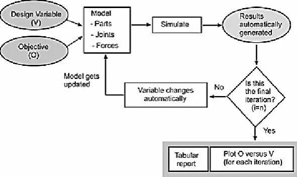
able and objective function. The effectiveness of the DS method consists in the fact that it is auto -matically controlled and it auto-matically gener -ates results [4]. In Figure 1, the principle of solu -tion when using this method is shown.
The DS method enables effectively varying a single design variable (V) across a range of values.
From the simulation and generated results it is possible to determine the best value of V and approximate sensitivity of the structure on V for which the following relation stands:
− − + − − =
− −
+ +
1 1 1
1 2 1
i i
i i
i i
i i
i OV VO OV VO
S (1)
where: O – is the objective value,
V – is the design variable and I is the itera -tion number.
For the design study the table also includes a column of approximate design sensitivities for each trial. The approximate design sensitivity is the average of the sensitivity with respect to the previous trial and the sensitivity with respect to the following trial.
Before each measurement a measure is select -ed and it is specifi-ed whether to use the minimum, maximum, average or last simulation value of the measure as the objective value.
The objective values are useful only if the outputs from the simulation are objective [5, 6]. These values can only be guaranteed by more complex and multiple simulations [7]. By em -ploying Design Study analysis the following can be determined:
• how the performance varies with changes in the design variable,
• optimal values of the design variable in the range of input parameters,
• the approximate sensitivity of the design vari -able; i.e. the rate of change of the performance with respect to the variable.
SENSITIVITY ANALYSIS OF PUMPING
UNIT
The pumping unit is used to recover oil (Fig. 2). When the walking beam ABC is horiyontal, the force acting in the wireline at the well head is F. The present model solves torque which must be exterted by the motor in order to overcome this load. The horse-head C weighs m1 and has a center of gravity at Tc. The walking beam ABC has a weight of m2 and a center of gravity at TB, and the counterweight
has a weight of m3 and a center of gravity at TW. The pitman, AD, is pin-connected at its ends and has negligible weight.
SIMULATION OF SOLID MEMBERS
Virtual prototype of pumping unit was mod -eled in an environment program ADAMS / View. This Model was made of the elements for the for -mation of rigid bodies – LINK (Fig. 3). Created optimization variable DV_1 (Design Variable) was the driving torque and the objective function was y coordinate of ED vector position, for which measuring function Point-to-Point Measure was created [8, 9, 10].
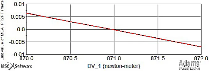
The simulations were performed at the five input values of the drive torque values and y co -ordinates of the position vector were recorded at the end (Fig. 4).
The refinement of the range of input values were made 3 times. If insufficient value of the drive torque was used, the body ED moves up Fig. 2. Kinematic scheme of pumping unit
(automated iterations)
Fig. 3. Kinematic scheme of pumping unit (automat -ed iterations) and modify DV
(positive values of measured position) and when of sufficient value of drive torque is used, the body moves down (negative values of measured position). Therefore, the minimum value the drive torque is the state when the measured value of the position vector component approaches to zero (green course in the figure 4). The minimal torque of the motor pump station for drawing oil, which must be developed to pull the rope with oil wells is 871 Nm (Fig. 5).
SIMULATION OF FLEXIBLE MEMBER
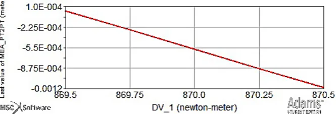
For this analysis ABC beam was repla -ced by elastic (Fig. 6) and analysis was repe -ated for the same conditions as the previous. The flexible body oscillated around the value -5,5∙10-4 (Fig. 7) in the beginning of investi -gation and after stabilizing body ED is moved up or down depending on the size of the torque
[10, 11, 12]. It had to be read not at a minimum torque at the intersection of zero but at the val -ue of -5,5∙10-4. Minimum torque by consider -ing a flexible body ABC to pull the rope with oil wells is 870 Nm.
It must be said that in this case the difference between the value of rigid bodies torque at (871 Nm) and a deformable bodies (870 Nm) is neg -ligible, but it should be understood that the ap -propriate use of elastic bodies by the solver ap -proaches generates more realistic results.
Figure 8 shows the method of DS depen -dence of the input variable (torque) and the ob -jective function (component of position vector) by considering a flexible body [13, 14, 15].
CONCLUSIONS
Experimenting with a real technical sys -tem is usually time and money consuming, and it does not guarantee the optimal solution. In the last few decades several commercial soft -ware applications for solving the dynamics of CMSs representing various mechanisms have been developed. Several computer programs allowed the automatic generation and solution of equations of motion. This enables designers to create a VP of designed mechanical equip -Fig. 5. DS dependence of input variable (torque) and the objective function (component of position vector)
Fig. 6. DS by considering one flexible body of system (ABC)
ment. The optimisation of these VP means the determination of the values of the proposed pa -rameters of a given equipment so that the be -haviour of the system was optimal with regard to a chosen criterion – usually a function of properly selected design variables.
Acknowledgements
This work was supported by the Slovak Grant Agency VEGA 1/0795/16 and VEGA 1/0234/13.
REFERENCES
1. Pechac P., Saga M., Guran A., Radziszewski L.: Implementation of memetic algorithms into struc -tural optimization, Source of the Document Komu -nikacie, 18(1a), 2016, 64-69.
2. Bendose M.P., Kikuchi N.: Generating Optimal Topologies in Structural Design Using a Homog -enization. Method, Computer Methods in Applied Mechanics and Engineering, 71(1), 1988, 197-224. 3. Palcak F.: Program MSC ADAMS. V Autho -rizedtraining center for MSC. ADAMS [online]. 2009 [cit. 2010-11-3]: http://atc.sjf.stuba.sk/msc_ adams.html.
4. http://simcomcompanion.mscsoftware.com/ infocenter/index?page=content&cat=2012_ A D A M S _ D O C S & c a t = 2 0 1 2 _ A D A M S _ DOCS&channel=DOCUMENTATION.
5. Krajcovic M. et al. Intelligent Manufacturing Sys -tems in concept of digital factory.Communications scientific letters of the University of Žilina, 15(2), 2013, 55-63.
6. Levy R., Parzynski W.: Optimality Criteria Solu -tion Strategies in Multiple-Constraint Design Opti
-mization. AIAA Journal, 20(5), 1982, 708-715. 7. Arnold, M., Schiehlen, W.: Simulation Techniques
for Applied Dynamics, CISM Courses and Lec -tures, Springer Wien : New York, vol. 507, 313. 8. Grega R., Homisin J., Puskar M.: The chances for
reduction of vibrations of vibrations in mechani -cal in mechani-cal system with low-emission ships combustion engines, International journal of mari -time engineering, vol. 157, 2014, 235-240. 9. Mocilan M., Zmindak M., Pastorek P.: Dynamic
analysis of fuel tank, Procedia Engineering, vol. 136, 2016, 45-49.
10. Vasko M., Guran A., Jakubovicova L., Kopas P.: Determination the Contact Stress Depending on the Load Rate of the NU220 Roller Bearing, Com -munications, 15(2), 2013, 88-94.
11. Vavro J., Vavro J., Kovacikova P., Kopas P., Handrik M.: Simulation and analysis of defect dis -tribution in passenger car tire under dynamic load -ing, Applied Mechanics and Materials, vol. 611, 2014, 544-547.
12. Zmindak M., Radziszewski L., Pelagic Z., Falat M.:Fem/bem techniques for modelling of local fields in contact mechanics, Komunikacie, 17(3), 2015, 37-46.
13. Stancekova D., Semcer J., Derbas M., Kurnava T.: Methods of Measuring of Residual Stresses and Evaluation of Residual State of Functional Surfac -es by x-ray Diffractometric Methods, J. Manufac -turing Technology, 13(4), 2013, 547-552.
14. Cubonova N.: Postprocessing of cl data in CAD/ CAM system edgecam using the constructor of postprocessors, Manufacturing Technology, vol. 13, 2013, 158-164.
15. Caban J., Droździel P., Barta D., Liščák Š.: Vehicle tire pressure monitoring systems, Diagnostyka, 15(3), 2014, 11-14.