of the Human Brain
Katastrofy naczyniowe a układ żylny mózgu człowieka
1 Department of Normal Anatomy, Wroclaw Medical University, Poland
2 Department and Clinic of Anesthesiology and Intensive Therapy, Wroclaw Medical University, Poland 3 Department of Internal and Occupational Diseases and Hypertension, Wroclaw Medical University, Poland
Abstract
Objectives. The goal of the study was to assess the contribution of the venous system to human brain vascular catastrophe.
Material and Methods. Vascular examinations comprised material consisting of 352 normal brains aged 18–71 years (162 females and 190 males) and 52 elderly corpse brains with subdural hematomas from the collection of Prof. Jerzy Dymecki, Neuropathology Dept., Psychiatry and Neurology Research Institute, Warsaw. The survey methods included injections filling vessels with LBS 3022 colored latex mixtures and image computer analysis with the BVS 6471 and BVS 6472BVS systems of Robotron Berlin (Germany), FAEG 200 of VEB Carl Zeiss Jena, as well as Cytochromics, Imtronic, Elf v-42, Scion for Windows 98, and Image J. Due to significant differences in the applied equipment, programs working in each system proved to be incompatible.
Results. Subdural hematoma pathomechanisms were observed, mathematical analysis was carried out on the spe-cial susceptibility to bridge vein rupture due to mechanical characteristics (right angle, small lumen, short section), parasinus type, and vascular rupture tendency depending on skull shape (long-headed skulls seemed more suscep-tible than short-headed ones). Angular structures of the dura mater in the area of venous vessel penetration are discussed and hematoma capsule vessel morphology assessed.
Conclusions. On cerebral athropy bridge veins get broken. Cerebral venous system plays an important role in sub-dural hematoma pathomechanism. Human brain venous system is characteristic for a large number of variations which considerably influence its clinical image (Adv Clin Exp Med 2010, 19, 2, 163–176).
Key words: subdural hematoma, bridge veins, bridge vein typology, influence of skull shape on bridge veins, angu-lar structures of the dura mater.
Streszczenie
Cel pracy. Ocena udziału układu żylnego w katastrofach naczyniowych mózgu.
Materiał i metody. Do badań naczyniowych wykorzystano 352 prawidłowe mózgi osób w wieku 18–71 lat (162 kobiety i 190 mężczyzn), 52 mózgi z krwiakami podtwardówkowymi osób zmarłych w wieku podeszłym, które zostały udostępnione do badań przez prof. dr. hab. Jerzego Dymeckiego z Zakładu Neuropatologii Instytutu Psychiatrii i Neurologii w Warszawie. Zastosowano iniekcyjną metodę badań i wypełnianie naczyń mieszaninami kolorowego lateksu LBS 3022. Komputerową analizę obrazu wykonano w systemach BVS 6471, BVS 6472BVS firmy Robotron Berlin (NRD), FEAG 200 produkcji VEB Carl Zeiss Jena, Cytochromics, Imtronic, Elf v-42, Scion for Windows 98, Image J. Ze względu na istotne różnice sprzętowe oprogramowanie pracujące na każdym systemie nie jest kompatybilne.
Wyniki. Prześledzono patomechanizm wylewów podtwardówkowych, przeprowadzono analizę matematyczną i określono szczególną podatność na zerwanie żył mostkowych z uwagi na własności mechaniczne (kąt prosty, mały przekrój, krótki odcinek) typ z obecnością parasinus, tendencję do zrywania się naczyń w zależności od kształtu czaszki (bardziej podatne są czaszki długogłowe niż krótkogłowe), omówiono konstrukcje łukowate opony twardej w miejscu wniknięcia naczyń żylnych, oceniono morfologię naczyń w torebce krwiaka.
An analysis of the available literature shows that there is a great discrepancy in the overall description of brain venous system morphology, especially in the fetal and geriatric age. Arterial topography differs from that of cerebral veins. Starting from the circulus arteriosus, arteries are arranged in the form of ascending branches. Veins collect in a common outflow trunk in a median line, similarly to the crown of a tree. Cerebral veins are very characteristic for diversity of form and topography and compose a large blood reservoir connected more intensely than arteries with the extracranial vascular system. Dura mater sinuses play an important role in the cerebral circulation. In neuropathology and experimental papers, the role of the venous system in cerebral circulation disturbances is discussed. Venous areas of prac-tical significance call for new cognitive require-ments in traditional anatomy. Assessment of the individual variability of cerebral venous vessel is of great practical and theoretical importance. It helps in understanding pathological processes such as venothrombotic transformation and cir-culation disturbances resulting from percussive and hyperplastic problems. Acute venous stasis, large oscillations in intracerebral pressure, cra-niocerebral injury, and surgical interventions or severe strokes are common causes of fatal com-plications. The not fully understood pathology and morphology of the cerebral venous system is an obstacle in thorough surveys. It is strictly con-nected with the difficulty in venous system imag-ing as well as with its unrecognized importance. A literature analysis shows a large discrepancy in cerebral vein morphology and typology as well as scarce data concerning bridge veins [8, 11, 18, 22–26, 28, 36] point at disturbances in cere-bral circulation coexisting with bridge vein dam-age. Bridge veins, which are terminal portions of superficial cerebral veins in the dura mater sinus connection, appear to be an interesting object of observation. In their own studies, the present authors followed their number, ostia angles, and variability [22–25]. They play an important role in the pathomechanism of subdural hematomas. In old age, bridge veins are overstretched and rup-ture. Such observations are included in literature [3, 10, 27, 42, 48]. Perese [36] emphasizes their clinical importance and the danger of bridge vein injury during surgical procedures. The goal of the present study was to assess the contribution of the cerebral venous system to vascular catastrophe based on mathematical analysis.
Material and Methods
The material comprised 352 brains aged 18–71 years (162 females and 190 males), 52 males with subdural hematomas from elderly corpses origi-nating from the collection of Prof. Dymecki, Dept. of Neuropathology, Psychiatry and Neurology Research Institute, Warsaw.
Injections with mixtures of LBS 3022 colored latex, computer image analysis with the systems BVS 6471 and BVS 6472BVS from Robotron Berlin (Germany), FAEG 200 from VEB Carl Zeiss Jena, Cytochromics, Imtronic Elf v-42, Scion for Windows 98, and Image J, and mathematical anal-ysis were applied. Due to equipment diversities, the programs were not compatible in every system. Image transformation is divided into three basic stages: acquisition, collection, and processing.
Results
Fig. 1. Outflow of bridge veins Ryc. 1. Schemat ujścia żył mostkowych
Fig. 2. Frontal lobe bridge veins flowing separately to the sagittal sinus (two red arrows)
Ryc. 2. Żyły mostkowe płata czołowego uchodzące oddzielnie do zatoki strzałkowej górnej dwie czerwone strzałki
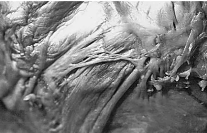
Fig. 3. Parietal lobe veins char-acteristic for their outflow at an acute angle (white arrow); they are significantly longer than the frontal lobe veins Ryc. 3. Żyły płata potylicznego charakteryzują się ujściem pod kątem ostrym (strzałka biała), są znacznie dłuższe niż żyły w okolicy płata czołowego
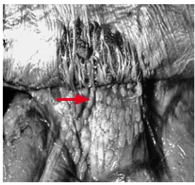
Fig. 4. Diagram of the common outflow of bridge veins, marked with a red arrow
Ryc. 4. Schemat wspólnego ujścia żył mostkowych zaznaczony czerwoną strzałką
Fig. 5. Common outflow of bridge veins to the parasi-nus. Bridge veins are short with small diameter and they flow out at a right angle
Ryc. 5. Wspólne ujście żył mostkowych do parasinus. Żyły mostkowe są krótkie, o małej średnicy, uchodzą pod kątem prostym
Fig. 6. Rare bridge-free form Ryc. 6. Rzadka postać bezmostkowa
Fig. 7. No bridge veins, strongly developed arachnoid granulosis
The influence of venous length and its rela-tionship with breaking force were assessed.
Venous Length Analysis
Longer vein analysis: l2 = n · l1, vein unitary elongation
100
1
1
⋅
∆
=
l
l
E
(%),Short vein:
100
11
⋅
∆
=
l
l
E
(%),Long vein: l2 = n · l1 so
100
(%)
1
100
(%)
11 1
2
=
⋅
∆
⋅
=
⋅
⋅
∆
=
E
l
l
n
l
n
l
E
(%)
100
1
(%)
100
1 1
1
2
=
⋅
∆
⋅
=
⋅
⋅
∆
=
E
l
l
n
l
n
l
E
The authors concluded that in the case of a short vein, the same length Δl is possible at smaller values of relative deformation. Short vein deformation by the same Δl value results in n times smaller deformations in a long vein so that the tension is n times smaller and the long vein is less susceptible to rupture. With the breaking force, activity a short vein will rupture sooner than a long one.
Influence of Venous
Cross-Section
Veins are made of the same material with sim-ilar qualities (Young’s module).
Fig. 8. Diagram of veins of different cross-section Ryc. 8. Schemat żył o różnej średnicy
Where δ1,2 is the tension breaking the first and
second vein,
1 1 1
=
S
P
δ
S1,2 the horizontal cross--sections of the first and second vein,
2 2 2
=
S
P
δ
S2 = n · S1, then
2 1 1
=
S
P
δ
,n S P n S n
P 1
1 1
1 1 2
1 δ
δ = ⋅ =
⋅ =
The tension in the vein is n times smaller as the lumen is n times larger. In the frontal lobe area, especially in its front part, thin and short bridge veins are observed.
The Influence of Angle
Fig. 9. Diagram of right and acute angles Ryc. 9. Schemat kąta prostego i ostrego
The influence of angle can be explained by the example of the force driving a nail at right and acute angles. In the case of a slanted nail, the force Z will cause drawing out of the board =sinα
P Z
, Z = P · sin(α), α = 90, so sin(90) = α, Z = P. With the same external force affecting straight and slanted veins, smaller tension appears in the slant-ed vein.
With cerebral atrophy, bridge veins rupture.
Fig. 10. Diagram of cerebral atrophy and bridge vein rupture
Ryc. 10. Schematyczne przedstawienie zaniku mózgu i zrywanie się żył mostkowych
The pathogenesis of chronic subdural hema-toma arouses many controversies. Bridge vein rupture results in blood collection in the sub-dural area. Subsub-dural hematoma capsule vessels were assessed [1]. Pickworth’s method and image computer analysis were used. Small vessels were visualized. Their width varied between 15–20 μm and in larger ones it reached 70 μm. The presence of sinusoidal vessels belongs to the next stage. Along with hematoma growth, the vessels increase in length. Hemorrhagic centers at various stages of organization are located nearby. The vessels undergo qualitative and quantitative changes, fol-low from growth factor, and cause hematoma vol-ume increase. Also, vessel formation, simultane-ous rupture, and repeated hemorrhage contribute to constant growth of the hematoma.
Influence of Skull Shape
on Brain Atrophy
Senile brains constituted 77% of the examined material. Cerebral ageing is accompanied by atro-phy and subdural area extension, which results in bridge vein stretching. In order to explain the problem, the formulation of a mathematical model was attempted using Leja’s manual [29]. Unitary elongation (E) was established, which helps to determine which vein is most susceptible to rupture. The assumption was made that veins were made of the same material of identical Young module. Unitary elongation was defined with the formula:
%, where 100
1
0
1 ⋅
− =
l l E
l0 initial length, l1 post-elongation length. Fig. 11. Brain with subdural hematoma. Specimen from Prof. Dymecki’s collection
Ryc. 11. Mózg z krwiakiem podtwardówkowym, pre-parat z kolekcji prof. Jerzego Dymeckiego
Fig. 12. Hematoma capsule vessels, vessel formation, and rupture. Subdural hematoma vessels visualized with Pickworth’s method and processed with a com-puter image transformation system. They are linear and divided of ramifications (white arrow), they break easily and form blood pools (black arrow)
Ryc. 12. Naczynia torebki krwiaka, nowotworzenie się naczyń i ich pękanie. Naczynia krwiaka podtwardów-kowego uwidoczniono za pomocą metody Pickwortha, a następnie komputerowego systemu przetwarzania obrazu. Są one linijne, pozbawione odgałęzień (biała strzałka), łatwo pękają i tworzą się rozlewiska (czarna strzałka)
Fig. 13. Cranium sagittal cross-section, elliptic shape Ryc. 13. Eliptyczny kształt przekroju strzałkowego czaszki
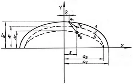
Fig. 14. Vein stretching as a result of brain surface abasement (in sagittal cross-section)
Vein stretching due to the atrophy, where 1 is the cranial surface, 2 – the original brain surface (before atrophy), 3 – the brain surface after atro-phy, δ – the distance of the vein’s upper-end anchor-ing, and s – the distance of the vein’s lower-end anchoring; when s = δ it is a vertical vein and s ≠ δ a slanted (oblique) vein. The original vein length L0 amounts to the A1 B3 section length. The distance between the cranium and brain surface was estab-lished as λ = b1 – b2. Cerebral surface abasement in
relation to the surface took place in the plane with sagittal cross-section by the h = b1 – b3.When h = λ, the brain is at the pre-atrophic stage. When h > λ, atrophy takes place, as described with the
index λ
h k = ,
with k =1, 2, … n. If k = 1, the stage is described as initial. The following elongation was defined ε for fixing points denominated by δ and S:
(
)
(
)
(
)
(
)
[ ]
% 100 1 1 1 1 1 2 2 1 1 2 1 1 2 2 2 1 1 2 1 1 2 × − − − ⋅ − − − ⋅ + − − − ⋅ ⋅ − − − ⋅ + − = λ λ δ δ λ λ δ δ ε a s b a b s a s k b a b sThe calculations require the data a1, b1, δ, λ, and S. The calculations are made for two types of cranium (short and long). Table 1 presents the adapted data.
Table 1. Vein stretching in short and long craniums in the case of brain atrophy
Tabela 1. Obliczenia dla czaszki krótkiej i długiej w przy-padku zaniku mózgu
Short cranium
(Krótka czaszka) Long cranium(Długa czaszka
a1 9 11
b1 8 8
Types λ 1 1
Types δ 0–4 0–4
S 0–4 0–4
Fig. 15. Sample results of calculations, vertical veins S = δ
Ryc. 15. Przedstawienie przykładowych wyników obliczeń, żyły pionowe S = δ
Values of E decrease along with λ and S in-creases.
Table 2. Calculations for short and long cranium veins flowing out at a right angle
Tabela 2. Obliczenia dla czaszki krótkiej i długiej żył uchodzących pod kątem prostym
Short cranium (Krótka czaszka) E (%) Long cranium (Długa czaszka) E (%)
λ
h
k = δ = 0 S = 0 δ = 1 S = 1 δ = 2 S = 2 δ = 3 S = 3 S = 4δ = 4 δ = 0 S = 0 δ = 1 S = 1 δ = 2 S = 2 δ = 3 S = 3 δ = 4 S = 4
1 0 0 0 0 0 0 0 0 0 0
Fig. 16. For all the cases of δ = 1 cm, the angle was changed. Angle changes were realized by S value changes
Ryc. 16. Dla wszystkich przypadków δ = 1 cm zmie-niano tylko kąt. Zmiany kąta realizowano, zmieniając wartości S
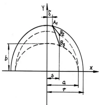
Fig. 17. Diagram of bridge veins in a short cranium. The distance from the vein’s upper-end anchoring,
s – the distance from vein’s lower-end anchoring; when s = δ it is a vertical vein, when s ≠ δ a slanted vein. The vein’s initial length l0 amounts to the A1 B1
section length.
Ryc. 17. Schemat układu żył mostkowych w czaszce krótkogłowej: Odległość zamocowania górnego końca żyły, s – odległość zamocowania dolnego końca żyły, gdy s = δ żyła pionowa, gdy s ≠ δ żyła ukośna, począt-kowa długość żyły l0 odpowiada długości odcinka A1 B1
(
)
(
)
(
)
(
)
[ ]
% 100 1 11
2 2 2
2 2
2 2 2
2 2
×
−
− − ⋅ − − − + −
− − ⋅ ⋅ − − − + − =
λ λ
δ δ
λ λ
δ δ
ε
r s r
r s
r s k
r r
s
Table 3 presents calculations results.
Table 3. Oblique vein stretching in short and long craniums
Tabela 3. Rozciąganie żył ukośnych w czaszce krótkiej i długiej
Short cranium (Krótka czaszka) E (%) Long cranium (Długa czaszka) E (%)
λ
h
k = S cm 1.5 S cm 1.75 S cm 2 S cm 2.25 S cm 2.5 3S cm S cm 1.5 S cm 1.72 S cm 2 S cm 2.25 S cm 2.5 S cm 3
1 0 0 0 0 0 0 0 0 0 0 0 0
Oblique vein stretching is far more delicate than vertical vein stretching. The elongation value E is even four times smaller than for perpendicular veins when δ = 1 and S = 1. Oblique veins were found to be less susceptible to rupture. In a short cranium, oblique veins are less liable to rupture. In the case of the same value of force activity, veins of smaller lumen which are oblique, short, and with perpendicularly outflow will rupture sooner. In subdural hematomas, bridge-free forms were not observed. From the anatomical point of view, mul-tiple vertically running bridge veins favor subdu-ral hematoma formation. It was found that bridge vein shape influences its mechanical resistance.
It is interesting whether the site of bridge vein rupture in located on the cerebral or meningeal side. Stophord [45] discusses bridge vein slabbiness.
Fig. 18. Torose and cylindrical vein rupture outline: F1 upper cross-section, cone base, F2 vein rupture
cross-section.
Ryc. 18. Schemat zrywania się żyły o kształcie walco-watym i cylindrycznym: F1 – przekrój górny, podstawa
stożka, F2 – przekrój zrywania się żyły
Calculations were based on the following model:
F1 = 2 ∙ π ∙ r1 ∙ δ, F2 = 2 ∙ π ∙ r2 ∙ δ, r1 = 2 ∙ r2,
δ
π
δ
π
δ
⋅
⋅
⋅
=
⋅
⋅
⋅
=
=
2 1
1
1
F
P
2
P
r
4
P
r
,δ
π
δ
⋅
⋅
⋅
=
=
2 2
F
P
2
P
r
2
,
2
2
4
22
2
1
=
⋅
⋅
⋅
=
P
r
r
P
δ
π
δ
π
δ
δ
.
With the above assumptions concerning bridge vein shape in the form of a truncated cone, the vein may undergo rupture only at the cerebrum joint site as the tension there is twice as large. In the case of veins of torose shape, the break may take place accidentally at any location as the ten-sions along the whole vein length are the same as for their mechanical values. In brain atrophy, due to the cerebral mass decrease, the subdural area increases and hypotension grows. Hypotension P causes vein load in the horizontal direction
(q value on the vein unit) which can be derived from the formula q = p × r. This means that in the horizontal direction the load is r times greater than in the vertical direction and the vein undergoes breaks along its length. At the site of bridge vein outflow, characteristic arcs are formed resembling architectual constructions and they are flat, circu-lar, or parabolic. For frontal veins, a static outline of a biarticular circular arc is mostly probable.
Fig. 19. Diagram of a flat arc Ryc. 19. Schemat łuku płaskiego
Fig. 20. A flat arc in the frontal area marked with an arrow; specimen photo
Ryc. 20. Łuk płaski w okolicy czołowej, zaznaczony strzałką, fotografia z preparatu
Fig. 21. Static diagram of a circular arc Ryc. 21. Schemat statyczny łuku kołowego
Fig. 22. Circular arc in the parietal area marked with a red arrow
α α α α
α−3sin ⋅cos +2 ⋅cos2
=P H
α – half of the arc’s middle angle.
[
]
⋅ ⋅ + ⋅ ⋅ − − ⋅ ⋅ ⋅ − ⋅ = 2 2 21951 . 0 34948 . 1 2 21951 . 0 97561 . 0 3 34948 . 1 021951 1 21951 . 0 97561 . 0 34948 . 1 97561 . 0 2 1 F H 6875, .7 6 2 1 6 15 15 81 + ⋅ =
⋅ =
r 0.97561
6875 . 7 2 15 sin = ⋅ = α
where cos α = 0.21951, α = 1.34948 rad, and H = 0.428P.
The arc bending moment amounts to: 2
2
2 x H r x
p
Mx= ⋅ − ′ −
The maximum moment occurs for the ordi-nate, which complies with the equation:
0, so
= Ox OMx 2 2 max 25 . 0 4 Pr 5 . 0 P H
x
+=
87 . 3 5044 . 0 25 . 0 428 . 0 4 Pr 5 . 0 2 2 2max = =
+ ⋅ ⋅ = r P P x ] [ 00 . 3 5 . 7 5 . 7 6875 . 7 428 . 0 877 . 3
2 2 2 2
max p P P x
M = ⋅ − ⋅ − − =
The bending moment in the arc mid-spread amounts to: ] [ 00 . 3 877 . 3 6875 . 7 428 . 0 877 . 3 2
max p P 2 2 P x
M = ⋅ − − =
Sometimes a low frontal arc with superior beam was observed. Such a static moment construction can be compared to a beam-arch bridge construction. It is easy to assess that such a construction is ten times smaller than the same arc without beam support.
Fig. 23. Diagram of a circular arc with a beam Ryc. 23. Schemat łuku kołowego z belką
Fig. 24. Specimen photo. Flat arc in the frontal area with a “beam”
It is important to note that the lower the arc, the smaller the resistance b at this particular site. A very flat arc with a seemingly circular shape is not resistant to strokes and considerable horizon-tal struts H occur which exceed the P force value by a factor of two or three.
Parabolic Arcs
Parabolic arcs are described by the equation x
l x l
f
F = 42 ( − ), where y is the arc’s vertical ordinate.
Fig. 25. Static diagram of an arc in the parieto-occipi-tal area
Ryc. 25. Schemat statyczny łuku w części potyliczno- -ciemieniowej
Fig. 26. Parabolic arc in the occipital area Ryc. 26. Łuk paraboliczny w okolicy potylicy
Equation for the horizontal strut has the fol-lowing form:
P P
f PL
N 0.488
6 128
15 25 128
25 =
⋅ ⋅ ⋅ = =
The bending moment at a distance x from the abutment results from the formula:
2
32 25 32
25
2 x Px l Px
P
Mx = ⋅ − ⋅ + ⋅
The extreme moment for the ordinate result-ing from the equation is:
0 0
0 =
x
Mx at a distance of x l ma = 509
M max = –0.02531, Pl = –3797P In the middle of an arc opening:
82 . 0 5 . 7 15 32
25 5 . 7 32 25 5 . 7 5 . 0 2
1 ⋅ ⋅ 2 =
⋅ + ⋅ ⋅ − ⋅ ⋅
= P P P
M
The authors concluded that in the case of par-abolic arcs of the dura mater, the striking force
should be P P 8203 . 0
003 . 3
times larger, namely 3.65 times larger for circular arcs. Occipital area arcs are well embedded, which allows the assumption of their non-articulated structure. On comparison of the influence of the arc’s eminence on internal values, it turned out that in the case of parabolic arcs, the bending moment in the mid-arc spread is the same, whereas the ratio of the cutting forces H1 and H2 is:
2 2
2 1 2
1:H fl :lf
H = .
In the case of eminence extreme values, the possibility of flat arc (l1 f1) and cut down exists. For circular arcs with H forces, it is identical to para-bolic arcs and the bending moment in the mid-dle of of the arc’s spread (eminence proportions shown below) is about 20% of that of a flat arc.
Fig. 27. Diagram of an ”arc within an arc” Ryc. 27. Schemat „łuku w łuku”
Fig. 28. Specimen photo of an arc within an arc Ryc. 28. Fotografia z preparatu „łuku w łuku”
Arcs’ Arrangement
in the Dura Mater in Relation
to the Superior Sagittal Sinus
Fig. 29. Arcs’ arrangement in the dura mater in rela-tion to the superior sagittal sinus
Ryc. 29. Ułożenie łuków w oponie twardej w odnie-sieniu do zatoki strzałkowej górnej
Most often, arcs are located at the site of fron-tal vein penetration at a distance of 2 cm from the superior sagittal sinus. The area of the penetration of the frontal vein or several veins forms a single arc. In the parietal region, the arcs are located more closely to the median line and in the occipital area; they are included within the sinus line. The arcs’ convex shapes in the frontal area are turned with their apices towards the sinus (perpendicularly) and in the occipital region they are turned at an acute angle. With stroke, the bending moment is additionally defined perpendicularly to the arc’s plane. However, it is largest in the abutment sites where the vertical force moment is twice as large as in the mid-arc spread. The additional abutment bending moment can be calculated with the for-mula (assuming the stroke at a 45° angle):
occipital area, the arc bases are characteristic for larger cross-sections and, moreover, they form a sequence of connected arcs which builds up their construction. In bridge-free forms, the systems of penetrating and crossing arcs can be compared to a roller surface construction. Such a surface’s car-rying capacity is several times larger than that of a single arc, with a similar amount of material used for the two constructions.
Fig. 30. Systems of penetrating and crossing arcs in bridge-free form
Ryc. 30. Układy przenikających się i krzyżujących łuków w postaci bezmostkowej
Discussion
Subdural hematomas have been analyzed by a number of authors [1–6, 8–10, 12–17, 19–21, 27, 30, 32–43, 46–49]. Cerebral senescence is accom-panied by its atrophy and increased subdural area, which result in bridge vein stretching [10, 14, 27, 42]. Stehbens [42] observed that bridge veins 1–4 cm from the superior sagittal sinus are the source of bleeding. Krauland [27] discusses isolat-ed vessel injury in contrecoup. In stroke particu-larly directed from the anterior or anteriolateral side, the brain undergoes dislocation and bridge veins rupture. Vance [46] observed the most com-mon location of subdural hematomas in the pari-etal area. However, there are no data concerning an anatomical predisposition to chronic subdural hematoma formation in advanced age.
belonged to the collection of Prof. Jerzy Dymecki, of the Dept. of Neuropathology, Psychiatry and Neurology Research Institute, Warsaw [22]. The pathologically affected material was compared with a large group of corpses (non-cerebral cause of death). In 29 cases, chronic subdural hematomas were located on the right side, in 18 cases on the left side, and in 5 cases they appeared to be bilat-eral. Chronic subdural hematomas were mostly located in the parieto-occipital area. The following issues were considered: the influence of the mor-phology of bridge veins flowing to the sagittal sinus on chronic subdural hematoma formation and the angle, length, cross-section, and type of bridge veins as well as the form of cavities and skull shape. The bridge veins’ outflow angle plays an important role from the point of view of mechanics. The presence of a right angle was found in frontal veins (45%) and parietal veins (55%), whereas in occipital veins the angle was always acute. The innovation of the study was the mathematical analysis of vein length, cross-section, susceptibility to rupture, skull type, and the structural characteristics of dura mater arc. The evaluation was based on data from [7, 29, 31, 44]. The evaluations suggest that a short vein with a small cross-section which flows at a right angle is more susceptible to rupture. The struc-ture of arcs formed by the dura mater at the site of bridge vein penetration was defined and the arcs’ influence on resistance was evaluated. Their vari-ety was described as well. The presence of a beam located superior to the arc strengthens the con-struction by a factor of ten. A parabolic arc is 3.65 times more resistant than a circular arc of the same
measurement parameters. The “arc within an arc” construction increases it four times in comparison with a single arc.
There is a strict dependence between structure and function. The rupture of a bridge vein causes blood collection in the subdural area. This results in a number of local reactions contributing to the for-mation of a special capsule separating blood mass from the dura mater [6, 9, 35]. Zülch [19] observed that a subdural hematoma is initially soft and easily separable from the dura mater. From the arachnoid side, the surface is smooth. The capsule adhering to the dura mater is 1–4 mm thick. The changes in the hematoma capsule were already described by [12, 34, 39, 47]. Sato and Suzuki [39] discussed the vessels’ role in hemorrhagic processes and distinguished small vessels and capillaries. In the present authors’ examinations the vessels of sub-dural hematoma capsule vessels were assessed [1]. Pickworth’s method and image computer analysis, which had not been used before, were used in that survey. Along with hematoma ageing, capsule ves-sels increase in length. Nearby there are very many hemorrhagic centers at various organizational stages. The vessels undergo quantitative and quali-tative changes, they follow from growth factor, and increase in size. The cerebral venous system plays an important role in the pathomechanism of sub-dural hematomas. Its considerable changeability means that the clinical profile in similar injuries is connected with special morphologic qualities. Mathematical analysis of the described structures explains both susceptibility and resistance to skull injuries under similar conditions.
References
Andrzejak R, Kędzia A, Ciszek B, Kędzia W:
[1] The assessment of subdural haematoma capsule vessels in image computer analysis. Computer supported research. VI KK Kowban 99, Polanica-Zdrój 28–30 October, p. 43–48. Antonie M, De Kersansan MC:
[2] Images radiologiques de cephal hematomes. J Radiol C 1958, 39, 163–166. Aronson SM, Okazaki H:
[3] A study of some factors modifying response of cerebral tissue to subdural haematoma J Neurosurg 1963, 20, 89–93.
Arseni C, Stanem M:
[4] Particular clinical aspects of chronic subdural haematoma in adults. Eur Neurol 1969, 2, 109–122.
Bromowicz J, Mert B:
[5] Acute subdural haematoma. Neur Neurochir Pol 1970, 4, 20, 5, 557–563. Christensen F, Husby J:
[6] Chronic subdural haematoma in infancy. Acta Neurol Scand 1963, 39, 4, 323–342. ChenWF, Atsuta T:
[7] Theory of Beam-Columns. McGraw-Hill. International Company 1977. Delmas A, Pertuiset B:
[8] Les veines du cortex cerebral. Distribution generale variante cordis, types veineux de dis-tribution. Comp. Rend. de l’Ass. des Anat. XXXVI Ren., Lyon 1949, 11–13, 185–193.
Decker R, Jacobs L:
[9] Unusual intracranial complication of head trauma. New York J Med 1974, 74, 832–837. Dymecki J, Ostrowska D:
[10] Late-life nontraumatic subdural haematoma morphological study. In: Cerebral ischemia and arterial hypertension. Ed.: Mossakowski MJ Pol Med Publ 1978, 150–156.
Ferner H:
[11] Verhandlungen der Anatomischen Gesellsachft (Erganzungsheft zum 105 Band) Anatomische Anzeigers 1958, 105, 237–244.
Friede L:
[12] Incidence and distribution of neomembranes dura mater. J Neurol Neurosurg Psychiatr 1971, 34, 439–446. Frowein RA, Keila M:
[13] Einteilung der traumatischen subduralen Hamatoma. Actuel Traumatol 1972, 2/4, 205–213. Gil R, Leferze JF:
[14] La regression des signes cliniques un cours des ematomes sous-duraux chroniques. Samaine des hopitaux 1974, 27, 8.
Goodel GL, Mealey J:
Kędzia A:
[22] Human cerebrum venous system and its clinical significance, Urban & Partner, Wrocław 2004. Kędzia A:
[23] Cerebral bridge veins in man. Folia Morphol 1984, 43, 4, 295–301. Kędzia A:
[24] Analysis of senile changes in human bridge veins in relation to susceptibility to subdural haematoma. Med Sci Mon 1998, 7–8, 18–19.
Kędzia A:
[25] Dura mater structure and function in senile age. Adv Clin Exp Med 2000, 9, 1, 21–28. König P:
[26] Zur Kenntnis des Verhaltens der ausseren Gehirnvenen zu den Hirnhauten. Zschr Anat Entv Gesch 1950, 114, 605–610.
Krauland W:
[27] Über die Quellen des akuten und chronischen subduralen Hamatoms. In: Zwanglose Abhandlungen aus dem Gebiet der normalen und pathologischen Anatomic. Heft 10, Thieme, Stuttgart 1961.
Lazorthes G, Poulhes J:
[28] Les amarres veineuses du ceveau et du cervelet. CR Ass Anat Strasburg 1948, 203–209. Leja F:
[29] Analytic geometry. PWN, Warszawa 1969. Leary S, Harishianu:
[30] Chronic subdural haematoma in the age. J Am Geriatrics Soc 1969, 17, 4, 380–383. Leontovicha V:
[31] Frames and Arches. Condensed Solution for Structural Analysis, New York–Toronto–London 1959.
Lindenberg R. Trauma of meninges and brain. In: Pathology of the Nervous System. Ed. J. Miackler. McGraw-Hill, [32]
New York 1971, v. II, 1705–1765. Mazur L:
[33] Brain hematomas formation mechanism. Neurol Neurochir Psych Pol 1961, 4, 445–457. Nowacki P:
[34] Subdural hematoma and haemorrhagic lesions of pachymeningosis haemorchagica interna type. Neuropat Pol 1980, 18, 2, 227–238.
Parkinson D, Chochinov H:
[35] Subdural Hematomas – some observations on their postoperative course. J Neurosurg 1960, 17, 901–904.
Perese DM:
[36] Superficial veins of the brain from a surgical point of view. J. Neurosurg. 1960, 17, 402–412. Raskind R, Glover MB, Weiss SR:
[37] Chronic subdural hematoma in the elderly: a challenge in diagnosis and treat-ment. J Am Geriatr Soc 1972, 20, 330–334.
Sakaki S, Bito S, Hayashi M, Yoshikowa K:
[38] Clinicopathological studies on cases of chronic subdural hematomas. The pathogenesis of hematoma and the mechanism of manifestation of symptoms. Brain Nerve (Tokyo) 1973, 25/2, 153–162. Exc.
Sato S, Suzuki J:
[39] Nonsurgical treatment of chronic subdural hematoma. II Ultrastructural observations of its capsule. Brain Nerve (Tokyo) 1973, 25/5, 557–563.
Schmitt W, Beneke G:
[40] Altersveranderungen der dura Mater und ihre Beziehugen zur Pachymeningiosis Vehrandlungen der Deutschen Gesellschaft fur Pathologie, 52-Tagung. Fischer, Jena 1968, 322–327.
Sosonkin ZS, Mikhlin V:
[41] O chroniczeskich subduralnych gematomach. Wopr Nejrochir 1962, 2, 49–51. Stehbens WF:
[42] Pathology of the cerebral blood vessels. Subdural hematoma. Mosby, Saint Louis 1972, 227–251. Szczygieł B:
[43] Radiological diagnostics of intracranial extracerebral hematomas. Doctorial thesis. Lublin 1968. S
[44] zymczyk J: Arces. Statistical calculations tables. Arkady, Warszawa 1961. Stophord J:
[45] The functional significance of the arrangement of the cerebral and cerebellar veins. J Anat Physiol 1925, 64, 257.
Vance BM
[46] Ruptures of surface blood vessels on cerebral hemispheres as a cause of subdural haemorrhage. AMA Arch Surg 1950, 61, 6, 992–1006.
Watanabe S, Shimida H, Ishii S:
[47] Production of clinical form of chronic subdural hematoma in experimental animals. J Neurosurg 1972, 37/5, 552–561.
Wolf G:
[48] Das subdurale Hematom und die pachymeningitis haemorrhagica interna. Springer, Berlin, Gottingen, Heidelberg 1962, I v.
Zülch KJ:
[49] Pathomorphology and pathophysiology of cranio-cerebral trauma. Pat Pol 1974, 25V, 3, 39–366.
Address for correspondence:
Alicja Kędzia
Department of Normal Anatomy Chałubińskiego 6a
Wrocław Medical University 50-368 Wroclaw
Poland
Conflict of interest: None declared