Vol.8 (2018) No. 2
ISSN: 2088-5334
Empirical Evaluation of Variation of Orifice Blocking Ratio
in a Tuned Liquid Column Damper Using Frequency Response
Function Measurement
Lovely Son
#, Marshal
#, Mulyadi Bur
# #Mechanical Engineering Department, Andalas University, Kampus Limau Manis, Padang, Indonesia E-mail: [email protected]
Abstract— Tuned liquid column damper (TLCD) is a simple technique used to increase the structure resistance to the external load.
This type of damper can effectively decrease the structure response when the TLCD parameters such as the natural frequency and damping factor are well selected. Even though several TLCD models have been proposed and many algorithms to optimize the TLCD parameters have been developed. However, it is very little research has been conducted to evaluate the TLCD damping factor experimentally. A simple empirical method for adjusting the TLCD damping factor is by varying the orifice-blocking ratio. In this research, 5 types of blocking ratio were trialled in the TLCD. They were without orifice and with 2, 4, 6 and 8 18 mm diameter orifices. The TLCD is positioned on the second floor of a Two-DOF shear structure. A frequency response function showing the ratio between the response magnitude and the excitation force on the structure in the frequency domain was recorded for each trial. The results show that the TLCDs with orifices damped vibrations more effectively than the one without orifice. The larger the blocking ratio, the larger the TLCD damping factor. Two 18 mm orifices were insufficient to damp the vibration as the blocking ratio is too large and TLCD is less responsive to the vibrations. The optimum condition of a U-Shaped TLCD blocking ratio was found to be 70.77% which corresponded to 4 holes of 18 mm orifice diameter. This type of TLCD dampened up to 80.04% of the vibration magnitude.
Keywords— TLCD; orifice; damping factor; blocking ratio
I. INTRODUCTION
The resilience of buildings to external forces is an area of increasing interest due to an increase in the construction of high-rise buildings for offices and resident requirements. The increasing height and span of structures decrease the structural stiffness and results in their increased vulnerability to environmental forces such as winds and earthquakes.
Passive vibration control technique such as seismic isolation, structural retrofitting using a braced frame, tuned mass damper (TMD), tuned liquid damper (TLD) and tuned liquid column damper (TLCD) have been utilized to improve the structural resilience to external forces [1]-[5].
Several researchers have proposed applications of the semi-active damper to the structure. Koo [6] has developed a suitable control method for semi-active tuned vibration absorber. Symans proposed a technique using semi-active damper for seismic protection of structures [7]. Pinkaew [8] evaluates the effectiveness of semi-active tuned mass damper under harmonic excitation.
The active control method has been proposed and developed to improve the vibration control performance. A comprehensive evaluation of active control in civil engineering from conception to full-scale applications has studied by Auperin [9].
Even though active control method has a better control performance in comparison to passive and semi-active control technique, but the complexity of the control components such as sensors, actuator, and the controller has limiting its application.
Recently, the passive vibration control technique using the dynamic vibration absorber has been extensively used to improve the structural resistance against the dynamic load such as wind and earthquake [10]. The reason is that the dynamic vibration absorber is simpler in construction and it has low operational cost. Furthermore, the performance of dynamic vibration absorbers can be as good as the active control technique if the absorber parameters are well designed.
for controlling the vibration level of structures. This liquid column device in a U-shaped container with an orifice achieves the same vibration characteristics as a tuned mechanical damper consisting of a mass and spring system (TMD). In comparison with other passive vibration control systems, TLCDs are simpler, easy to implement, have low construction and maintenance costs, and the damper can be used as a water storage device for the building [11]. Like other passive vibration control devices, the tuned liquid column damper (TLCD) is an energy-absorbing device that does not require an external power source for operation. The damping effect is generated by the hydrodynamic head losses that arise during the motion of the liquid inside the TLCD [12].
A TLCD works by absorbing the vibration energy of the structure so that the structure response becomes less than it would be if the TLCD was not present. The motion of the structural element on which the damper is attached induces a phase-delayed motion of the liquid mass inside TLCD column. This motion creates internal forces in the tube, counteracting the external forces. Additionally, the kinetic energy accumulating in the structural element is dissipated by turbulent damping forces, arising from fluid friction inside TLCD column and a built-in orifice plate with a small opening.
In order for the damper to perform well, it is important that the fundamental frequency of the liquid motion be tuned to the natural frequency of the structure. The fluid, natural frequency inside TLCD column depends on the TLCD dimension and the fluid length. The damping factor of the TLCD should be set to an optimal value to maximize effectiveness. Many studies have been conducted to obtain the optimum TLCD parameters using analytical methods [13] or numerical optimization technique [14]. However, even though several TLCD models have been proposed and many optimization algorithms have been developed, less study has been done to evaluate the TLCD damping factor experimentally.
Generally, the TLCD damping factors depend on the dissipation energy mechanism of the fluid inside TLCD such as fluid friction and turbulence [15]. A simple method to adjust the TLCD damping factor is by varying the orifice blocking ratio. The orifice-blocking ratio is defined as the ratio of the orifice close plate to the total cross-sectional area of the TLCD column.
The TLCD parameters design is aimed to reduce the first resonance peak of a two-DOF shear structure. In this study, the optimum condition of TLCD natural frequency is obtained by varying the fluid level. Next, determination of the optimum TLCD damping factor is performed by varying the number of holes on the orifice plate. Five variations of orifice blocking ratio were evaluated in the experiment.
II. MATERIAL AND METHOD
The fluid damping factor is a physical quantity accounting for energy dissipation and practically characterized by a dimensionless quantity, i.e., head loss coefficient in fluid flow. For the liquid flow in the TLCD, the energy dissipation is mainly caused by liquid passing through the orifice and changing its direction at turn elbows. The portion of liquid passing through the orifice is governed by the blocking ratio
of the orifice which is defined as the ratio of the closed region to the total area of the orifice plate. An empirical formula to predict head loss coefficient of liquid flow at a pipeline for a given blocking ratio is found as [12].
(
0.375)
2(
)
20.707 1
η= ψ + ψ −ψ − (1)
It parameterψ the in Eq. (1) denotes the blocking ratio. Since η in TLCD could be caused by several factors such as the transition of the TLCD cross-section, sharp-edged elbow, and fluid viscosity, therefore η needs to be modified based on the measured data for TLCD with various blocking ratio [15].
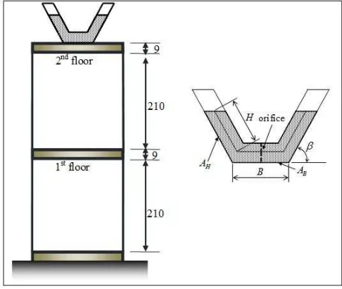
The structure model used in the research represents a two-storey building with a TLCD applied as a passive damper. The building model with the TLCD attached to the upper storey can be seen in Fig.1. The structure model consists of 2 masses, connected with four beam springs. The TLCD system is a U shaped water container as depicted in Fig. 1.
TLCD is used to attenuate the structure response at its fundamental frequency. For this purpose, TLCD parameters are designed so that its resonance frequency closest to the fundamental frequency of the structure. The orifice plate located in the middle of the TLCD horizontal column is utilized to vary the TLCD damping factor. The damping factor is varied by modifying the number of holes on the orifice plate. A non-dimensional parameter, orifice blocking ratio, is used to express the orifice holes variation.
The finite element modelling technique (FEM) usually used to represent the complex structure mathematical model that has several natural frequencies and vibration modes [16]. However, for a simple structure as used in this research, the mathematical model can be simply obtained using the Newton 2nd law of motion.
The structure model can be regarded as a two-DOF vibration system with TLCD as shown in Fig. 2. mf1 and mf2 are the lower and the upper floor masses.
Fig. 2 Two-DOF vibration model with TLCD
ke in Fig. 2 representing the equivalent stiffness of the spring beam as given by:
( )
312
4 b b
e
b
E I
k = ×
ℓ
(2)
Where Eb, Ib, and ℓbare the beam modulus of elasticity,
inertia, and length, respectively.
The governing equation of structure without TLCD is given by:
1 1 1
2 2
2
0 2
0 0
f e e
e e
f
m x k k x
k k x x m − + = − ɺɺ ɺɺ (3)
By assuming the response of the system x = Xsinωt, the equation of motion can be written as follows:
2 1 1 2 2 2 2 sin 0
e f e
e e f
k m k X
t X
k k m
ω
ω
ω
− − = − − (4)Because of X1sinωt and X2sinωt must be the nonzero values. Therefore Eq.(4) can be solved if the determinant of the first term in Eq.(4) is zero as expressed by:
2 1 2 2 2 0
e f e
e e f
k m k
k k m
ω
ω
− −
=
− − (5)
A solution of the determinant in Eq.(5) resulting in the characteristic equation of the system as follows:
(
2)(
2)
21 2
2ke−mf ω ke−mf ω −ke =0 (6)
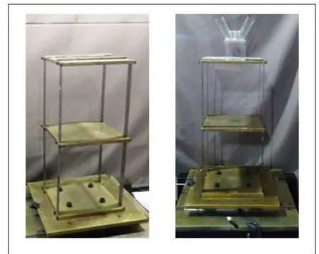
The apparatus used in the experimental study is shown in Fig.3. Two-storey building structure model was excited by the impulsive force using an impact hammer. The impact excitation is applied to the upper floor of the structure. The acceleration response of the building model was measured using an accelerometer. The acceleration signal from the sensor was conditioned using the signal amplifier and feed to the National Instrument (NI) signal analyzer. The acquired data by the analyzer is post-processed using MATLAB software. The MATLAB graphical toolbox used to display the frequency response function (FRF) and time domain response of the structure without and with TLCD. The TLCD mounted at the top of the structure model was designed to have the same natural frequency value as the structure’s fundamental frequency [10]. The TLCD absorber was designed to reduce vibrations at this fundamental frequency. In this research, 5 types of orifice blocking ratio were examined. They are a TLCD without an orifice and 4
TLCDs with orifices. Each orifice consisted of an 18 mm hole, and the TLCDs had 2, 4, 6, and 8 holes sequentially. The mass of each TLCD container was assumed to be the same.
Fig. 3 Structure model and experimental apparatus
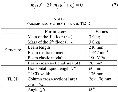
Table 1 shows the structure and TLCD parameters used in the experimental study. The floor mass and beam used in the experiment are made of steel whereas TLCD absorber is made of acrylic plate. The structural parameter values are the same as those used in the previous simulation study [14]. Because of mf1 = mf2 = mf then the characteristic equation of the system as expressed in Eq.(6) can be simplified as follows:
2 4 2 2
3 0
f e f e
m
ω
− k mω
+k = (7)TABLEI
PARAMETERS OF STRUCTURE AND TLCD
Parameters Values
Structure
Mass of the 1st floor (mf1) 3.0 kg
Mass of the 2nd floor (mf2) 3.0 kg
Beam length 210 mm
Beam inertia moment 1.667 mm4
Beam elastic modulus 190 MPa
Beam cross-sectional area (A) 20 mm2
TLCD
Horisontal liquid length (B) 60 mm
TLCD width 176 mm
Column cross-sectional area (AB = AH)
26× 176 mm
Angle (β) 60o
The natural frequencies of the structure are calculated by solving the characteristic equation of the system as given by:
1 0.618 e
f
k m
ω
= (8)2 1.618 e
f
k m
Calculation results of the structural natural frequency for the 1st and the 2nd vibration mode utilizing Eq.(8) and (9) are 2.30 Hz and 6.02 Hz, respectively.
The TLCD resonance frequency was selected so that its value closest to the fundamental frequency of the structure as given in Eq.(8). The TLCD resonance frequency is the function of TLCD dimensions and the fluid length inside TLCD column as given by [14]:
2 sin
A
eff
g L
β
ω
= (10)where
2 H
eff
B
A
L H B
A
= + (11)
Eq.(10) indicates that TLCD resonance frequency depends on the column angle (β) and the effective length of the fluid inside TLCD column (Leff). Because of β, AH, AB and B are kept constant, the TLCD frequency is varied during the experimental study by modifying the value of fluid level (H).
The experiment is performed for each configuration of the orifice holes. In each holes configuration, the optimum fluid volume inside TLCD column is investigated by minimizing the FRF peak near the fundamental frequency of the structure. Once the optimum fluid level obtained, the relationships between the magnitudes of frequency response function (FRF) to the orifice blocking ratio were analyzed. Measurements of the structure model FRF were conducted for each orifice blocking ratio. The graphs of the FRF obtained for each blocking ratio were compared to the FRF of the structure using TLCD without orifice.
III.RESULTS AND DISCUSSION
Table 2 shows the configuration of orifices used in the experimental study. The configuration 1 is without an orifice and configuration 2, 3, 4, and 5 those using 8 holes, 6 holes, 4 holes, and 2 holes orifices respectively. The corresponding orifice blocking ratio values were 0 %; 41.43%; 56.15%; 70.77% and 85.37%. For each orifice configuration, the holes diameters are kept constant.
TABLEII
CONFIGURATION OF ORIFICES
No. Orifices configuration Blocking ratio
1 No blocking ratio
2 41.43%
3 56.15%
4 70.77%
5 85.37%
In the case of TLCD without orifice (No blocking ratio), the TLCD damping factor is mainly generated by the hydrodynamic head losses that arise during the motion of the liquid inside TLCD. These losses come from friction
between fluid and TLCD surface and minor losses from TLCD column elbows.
The 2 DOF shear structure is tested under 2 conditions; with and without a TLCD as shown in Fig. 4. The natural structure frequency is obtained by impact test using an impact hammer.
Fig. 4 (a) Structure without a TLCD (b) Structure equipped with a TLCD
Water is used for TLCD fluid in the experimental study. The TLCD frequency is tuned to the 1st natural frequency of the structure by varying the vertical length of (H). The optimum water length is decided when the FRF peak is minimum. Once the optimal length H is selected, the TLCD damping is modified by changing the number of orifice holes.
During the experiment, the measured acceleration and the applied impulsive force are acquired by NI signal analyzer. The measured signals are feed to the PC and processed in MATLAB. The FRF is calculated from the ratio between the acceleration response and the impulsive force in the frequency domain.
Fig. 5 shows the FRF of 2 DOF shear structure obtained by impact test. The impact test is performed by exciting the structure with an impact hammer at the upper mass. The acceleration response is measured using an accelerometer located on the second floor of the structure. The impact force measured using the force sensor located at the tip of the impact hammer. It is shown in Fig. 5, the 1st and 2nd natural frequencies of the structure are 2.3 Hz and 6.1 Hz, respectively. These frequencies are closest to those calculated using Eq. (8) and (9). The FRF peaks magnitude at the first and the second natural frequencies are 4.198 (m/s2)/N and 3.186 (m/s2)/N, respectively.
Fig. 5 FRF of two DOF shear structure without TLCD
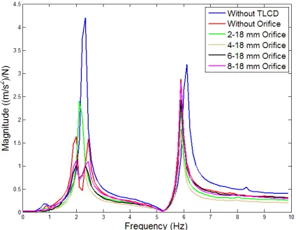
Several FRF of the structure without and with TLCD are measured to evaluate the effect of orifice blocking ratio variation to the TLCD performance. All of the measured FRF are shown in Fig. 6. It is shown that the FRF peaks without TLCD are higher compared to any with TLCDs. The TLCD with a 2-hole orifice was ineffective in dampening the vibrations. A more effective performance was obtained using 4, 6, and 8-hole orifice TLCDs which produced the lower FRF magnitudes. The 4-hole orifice TLCD produced optimal results with the lowest FRF magnitude.
Fig. 6 Comparison of FRF of structure with and without TLCD
The effectiveness of the TLCDs performance in the time domain is evaluated by comparing free vibration response of the structure without and with TLCD. Fig.7 shows the acceleration response measured at the second floor of the structure when the initial displacement is applied to the lower and upper floor masses. As depicted in Fig.7, one second after the initial displacement released, the structure is starting to vibrate. The acceleration response is recorded for 10 seconds as shown in Fig. 7. The magnitude of the vibrations in the structure used with each of the 3 effective TLCDs shows a decreasing acceleration over time as depicted in Fig. 7.
Fig. 7 Comparison of structure response in time domain with and without TLCDs
The acceleration response of the structure without a TLCD shows very slow decrease whereas the structure response is dampened more effectively when the 4, 6, and 8 holes orifice TLCDs are used. It can be shown from Fig.7 that the acceleration response of the structure obtained with TLCD decrease more 80% after 5 seconds.
IV. CONCLUSION
The experimental evaluation of TLCD shown that TLCDs with orifices were better than the one without in damping vibration. The larger orifice is blocking ratio, the better TLCD performance, except for the 2-hole orifice TLCD which was less effective than the TLCD without an orifice. The optimum 60o U-Shaped TLCD in this study had an orifice consisting of 4 18 mm holes and blocking ratio of 70.77%. This type of TLCD can dampen vibrations more than 80%.
NOMENCLATURE
ke structure equivalent stiffness N/m
Eb elastic modulus of beam N/m2
Ib inertia of beam m
4
b
ℓ beam length m
A beam cross sectional area m2
mf1 1
st
floor mass kg
mf2 2nd floor mass kg
H liquid level m
B horisontal liquid length m
AH vertical column cross-sectional area m
2
AB horisontal column cross-sectional area m2
Leff effective length of liquid m
Greek letters
η liquid head loss coefficient -
ψ blocking ratio of orifice -
β TLCD angle deg
Subscripts
eff effective
e equivalent
b beam
ACKNOWLEDGMENT
Financial support by publication research fund from Faculty of Engineering, Andalas University with contract number 004/UN.16.09.D/PL/2017 is gratefully acknowledged.
REFERENCES
[1] P.S. Harvey and K.C. Kelly, “A review of rolling-type seismic isolation: Historical Development and Future Directions,” Engineering Structures, vol. 125, pp. 521-531, 2016.
[2] S. Saloma, Y. Idris, H. Hanafiah and N. Octavianus, “Structural behaviour of steel building with diagonal and chevron braced CBF by pushover analysis,” IJASEIT, vol. 7.No.2, pp.716-722, 2017. [3] S. Elias, V. Matsagar and T.K. Datta, “Effectiveness of Distributed
Tuned Mass Damper for Multi-Mode Control of Chimney under Earthquakes,” Engineering Structures, vol. 124, pp. 1-16, 2016. [4] J.S. Love and M.J. Tait, “A Preliminary Design Method for Tuned
liquid Dampers Conforming to Space Restrictions,” Engineering Structures, vol. 40, pp. 187-197, 2012.
[5] F. Sakai, S. Takaeda and T. Tamaki, “Tuned liquid column damper-new type device for suppression of building vibrations,” Proceedings of the International Conference on High Rise Buildings, Nanjing, China, pp. 926–931, 1989.
[6] J.H. Koo, M. Ahmadian, M.A. Setareh and T.M. Murray, “In Search of Suitable Control Methods for Semi-Active Tuned Vibration
Absorbers,” Journal of Vibration And Control, vol.10, pp. 63-174, 2003.
[7] M.D. Symans and M.C. Constantinou, “Semi-active control systems for seismic protection of structures: a state-of-art review,” Engineering Structures, vol. 21, pp. 469-487, 1999.
[8] T. Pinkaew and Y. Fujino, “Effectiveness of Semi-Active Tuned Mass Damper under Harmonic Excitation,” Engineering Structures, vol. 23, pp. 850-856, 2001.
[9] M. Auperin, C. Dumoulin, G.E. Magonette, F. Marazzi, H. Forsterling, R. Bonefeld, A. Hooper and A.G. Jenner, “Active Control in Civil Engineering: From Conception to Full Scale Applications,” Structural Control and Health Monitoring, vol.8.No.2, pp.123-178, 2001. [10] L. Son, M. Bur and M. Rusli, “Design of Double Dynamic Vibration
Absorbers for Reduction of Two DOF Vibration System,” Structural Engineering and Mechanics, vol.57. No.1, pp.161-178, 2016. [11] M. Reiterer and F. Ziegler, “Combined Seismic Activation of a
SDOF-Building with a Passive TLCD Attached,”13th World Conference on Earthquake Engineering, Canada, pp. 2004.
[12] K.W. Min, Y.W. Kim and J. Kim, “Analytical and experimental investigations on performance of tuned liquid column dampers with various orifices to wind-excited structural vibration,” Journal of Wind Engineering and Industrial Aerodynamics, vol. 139, pp. 62-69, 2015. [13] J.C. Wu, C.H. Chang and Y.Y. Lin, “Optimal design for non-uniform
tuned liquid column dampers in horizontal motion,” Journal of Sounds and Vibration, vol. 326, pp. 104-122, 2009.
[14] L. Son, M. Bur and M. Rusli, “Response Reduction of Two DOF Shear Structure Using TMD and TLCD by Considering Absorber Space Limit and Fluid Motion,” Applied Mechanics and Materials, vol. 836, pp. 251-256, 2016.
[15] J.C. Wu, M.H. Shih, Y.Y. Lin and Y.C. Shen, “Design guidelines for tuned liquid column damper for structures responding to wind,” Engineering Structures, vol. 27. No.13, pp. 1893-1905, 2005. [16] M.S. Mahzabin, R. Hamid and W.H.W. Badaruzzaman, “Finite