ORIGINAL ARTICLE
Effects of Prestressing of the Ring Gear
in Interference Fit on Flexural Fatigue Strength
of Tooth Root
Shiping Yang
*, Yixing Ji, Yulin Mo and Tianyu Xia
Abstract
When the gearbox body interference is connected to the ring gear, prestressing occurs in the ring gear, which has a significant impact on the strength and life of the gear. Research on the prestressing of the inner ring gear is in the preliminary stage, and the distribution rule of the prestressing and the influence of each parameter on the interfer-ence prestressing have not been derived. In this paper, based on the method of calculating the prestressing of the thick cylinder in interference fit, the ring gear is found to be equivalent to a thick cylinder, and the distribution rule of prestressing of the ring gear in the interference fit is inferred. Then, by modeling and analyzing the gearbox body and ring gear in the interference fit using ABAQUS, the distribution rule of prestressing the ring gear in the interference fit is obtained through a numerical simulation. Finally, the prestressing of the ring gear in the interference fit is meas-ured using X-ray diffraction, and the distribution rule of prestressing of the ring gear in the interference fit is obtained through analysis. Compared with the distribution rule of prestressing in theory, numerical simulation, and experiment, the theoretical distribution rule of prestressing is amended through a statistical method, and a more accurate formula of prestressing is obtained. Through the calculation of the stress and bending moment in the dangerous section of the ring gear through prestressing, the formula for checking the tooth root flexural fatigue strength in the interfer-ence fit prestressing is inferred. This research proposes a tooth root bending strength conditional formula for the inner ring gear of the interference fit, which serves as a guide for the design and production of the actual interference joint inner ring gear.
Keywords: Interference fit, Ring gear, Prestressing, Tooth root flexural fatigue strength, X-ray diffraction (XRD)
© The Author(s) 2019. This article is distributed under the terms of the Creative Commons Attribution 4.0 International License (http://creat iveco mmons .org/licen ses/by/4.0/), which permits unrestricted use, distribution, and reproduction in any medium, provided you give appropriate credit to the original author(s) and the source, provide a link to the Creative Commons license, and indicate if changes were made.
1 Introduction
The interference fit is a method in which a container and contained item is fastened based on the magnitude of interference [1, 2]. In a planetary gear reducer [3], wind power gearbox [4], and other transmissions, owing to the requirements of the structure, the ring gear is always manufactured on the gearbox [5]. Thus, the material of the gearbox needs to be same as that of the ring gear, which increases the cost of the gearbox. If the gear-box is assembled with a ring gear in the interference fit, the gearbox can be processed using a common casting
material, reducing costs and enhancing the market com-petitiveness of these transmissions.
Prestressing occurs in the ring gear through the gear-box interference fit with the ring gear, which impacts the tooth root flexural fatigue strength of the gear. Therefore, it is necessary to calculate the prestressing of the ring gear in the interference fit, consider the effect on the dan-gerous tooth root section of the ring gear, and correct the formula of tooth root flexural fatigue strength. Among the research conducted on interference fit of a gear and its prestressing, Jiang et al. [6] calculated the prestress-ing of the gear and rprestress-ing in the interference fit based on a VK-63 gearing speed-up device. Based on a crankshaft gear, which is interference-fitted in the engine, Zou et al. [7] determined the relationship between the inner diam-eter of the gear, the magnitude of interference, and the
Open Access
*Correspondence: [email protected]
prestressing. Yan et al. [8] established the distribution rule of prestressing of the gear in the interference fit. Zhu [9] based on ANSYS, analyzed the relationship of the interference between the keyless joint and the maximum prestressing; Zhao et al. [10] based on ANSYS, built the prestressed mode of the planetary gear train of the trans-mission; Wang [11] analyzed the influence of prestress-ing on interference fit of dump truck axle; Kim et al. [12] simulated the hot assembly procedure of the external gear and axis in the interference fit, and predicted the amount of deformation of the teeth profiles, consider-ing the shrink-fittconsider-ing load and amount of expansion of the gear with major process variables, and the amount of shrink-fitting interference; Rahman et al. [13] established the relationship between the friction coefficient and the stress of the contact area by studying the shaft and bushing of the interference joint; Hao et al. [14] studied the contact stress of the interference fit of the planetary carrier based on the finite element method; and Fred-eric et al. [15] obtained the reduction coefficient of the fretting fatigue strength of the interference joint. These studies have proposed effective calculation methods for the design of interference fit gear or similar joints. At the same time, a comprehensive analysis of the effects of prestressing and contact stress on the gear teeth of the interference coupling gear was made. However, the cal-culation formula for the prestressing of the gear interfer-ence joint, especially the ring gear, has not mentioned nor derived.
Prestressing analysis of the interference fit is extremely complex, and a simple theoretical analysis cannot meet the requirements [16]. With further engineering applica-tions, the finite element method [17, 18] and trial method have been applied to the analysis of prestressing in an interference fit, and these methods can determine the distribution rule of prestressing of the gear in the inter-ference fit more accurately.
This paper is based on XE82 and XE93 yaw pitch reduc-ers [19, 20]. Focusing on the research target, the distribu-tion rule of prestressing of the gearbox interference fits with the ring gear in the elastic range are first deduced, and the theoretical curves of the internal gear in the interference fit of prestressing are drawn up. Then, the simulation curves of the prestressing of the ring gear in the interference fit are analyzed using ABAQUS. The pre-stressing of the ring gear in the interference fit is meas-ured through X-ray diffraction (XRD); the distribution rule of the prestressing of the ring gear in the interference fit is obtained through an analysis; and the trial curves of the prestressing of the ring gear in the interference fit are obtained. By comparing the distribution rule of prestress-ing of the theoretical curve, the simulation, and the trial curve, the accuracy of the prestressing formula of the
ring gear in the interference fit is verified. Finally, accord-ing to the calculation formulas of the tooth root bendaccord-ing fatigue strength, the meshing load of the ring gear and the prestressing of the interference fit in the dangerous section are synthesized. Then, the formula for checking the tooth root flexural fatigue strength is obtained, which can guide the design of the gearbox in the interference fit.
2 Mathematical Model of Prestressing of the Ring Gear in Interference Fit
In the calculation of the flexural fatigue strength of the tooth root, the gear is always regarded as a cantilever beam [21], and the location of the dangerous section is determined using a 30° tangent method. In a wind power planetary gear reducer, the ring gear is born not only by the meshing load of the planetary gear, but also the pre-stressing σt of the interference fitting when the gearbox body interference fits the ring gear. In a traditional thick cylinder, the formula of the prestressing of the inner cyl-inder in the interference fit is written as follows [22]:
where r1 is the radius of the inner cylinder, r2 is the radius of the outer cylinder, and p is the interference fit stress. As can be seen from [22],
where df is the joint diameter, δ is the amount of interfer-ence, Ea is the outer cylinder material modulus of elas-ticity (MPa), Ei is the inner cylinder material modulus of elasticity (MPa), and Ca and Ci are the coefficients of the inner and outer cylinder, respectively. The formulas are shown as follows:
where r1 is the inner radius of the inner cylinder (mm),
rf is the interference cylinder joint diameter (mm), r4 is the outer radius of the outer cylinder (mm), νa is the Pois-son’s ratio of the outer cylinder, and νi is the Poisson’s ratio of the inner cylinder.
Because the media of inner gear teeth are discontinu-ous, the inner cylinder is regarded as a thick cylinder, and
(1) σt=
pr22 r22−r12
1+r 2 1 r2
,
(2)
p= δ
df
Ca
Ea +
Ci
Ei
,
(3) Ca=
r42+rf2
r42−rf2 +νa,
(4) Ci=
rf2+r12
the pitch circle diameter of the inner gear is regarded as the inner diameter of the thick cylinder [23]. The pre-stressing formula of the ring gear in the interference fit is then determined as follows:
where ri is the radius of the combined surface, and rr is the radius of the inner gear’s pitch circle.
Then, based on the calculation formula of prestressing
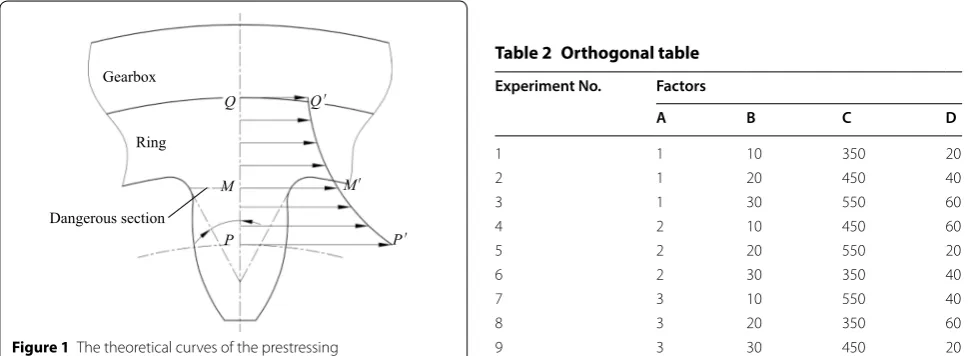
σt, the theoretical curve of the prestressing of the ring gear in the interference fit is obtained, which is shown in Figure 1.
3 Design of Experimental Scheme
Based on the prestressing formula of the ring gear in the interference fit, the ring gear’s modulus, the difference between the ring gear diameter and gear teeth diameter, the transmitted torque, and the combined length are cho-sen as the four key factors, and an orthogonal experiment on these four factors and three levels is conducted [24]. The models of the gearbox and ring gear in the interfer-ence fit are simulated and tested. The factor level table is obtained, as shown in Table 1.
Based on the orthogonal experiment on the four fac-tors and three levels, the orthogonal table is obtained, as shown in Table 2.
Nine groups of experimental data were calculated, and the theoretical curves of the prestressing from (5) σt= p·r
2 i ri2−r2
r
1+ r
2 r r2
= p·r
2 i ri2−r2
r +p·r
2 i ·rr2 r2i −r2
r · 1
r2
=A1+B1· 1
r2, experiments 1 through 9 are obtained. Then, the nine
groups of experiments were simulated and tested, and the simulation curves and experimental curves of the prestressing were obtained.
What we desire is an arm exoskeleton which is capable of following the motions of the human upper-limb accu-rately, and supplying the human upper-limb with proper force feedback if needed. In order to achieve an ideal controlling performance, we have to examine the struc-ture of the human upper-limb.
4 Simulation Based on ABAQUS 4.1 Modelling
The data from experiments 1 and 9 were chosen, and the ring gears and gearboxes were modelled using SolidWorks.
In experiment 1, the modulus of ring gear m = 1 mm, tooth numbers z = 24, pitch circle diameter d1 = 24 mm, outer diameter d = 46.5 mm, and tooth width b = 20 mm. According to the transmitted torque M of experi-ment 1, the magnitude of interference δ is calculated, and the magnitude of interference δ = 0.059 mm. The inner diameter of the gearbox d2 = 46.441 mm, outer diameter
d3 = 106.5 mm, and length l = 20 mm.
In experiment 8, the modulus of the ring gear m = 3 mm, tooth numbers z = 24, pitch circle diameter d1 = 72 mm, outer diameter d = 119.5 mm, and tooth width
Gearbox
Ring
Dangerous section
Q
M
QĄ
MĄ
P PĄ
Figure 1 The theoretical curves of the prestressing
Table 1 Horizontal factor
Factors Level 1 Level 2 Level 3
A Modulus of ring gear m (mm) 1 2 3 B Difference between outer diameter of
ring gear and diameter of root circle d (mm)
10 20 30
C The transmitted torque M (N·m) 350 450 550 D The combined length L (mm) 20 40 60
Table 2 Orthogonal table Experiment No. Factors
A B C D
1 1 10 350 20
2 1 20 450 40
3 1 30 550 60
4 2 10 450 60
5 2 20 550 20
6 2 30 350 40
7 3 10 550 40
8 3 20 350 60
b = 60 mm. According to the transmitted torque M of experiment 8, the magnitude of interference δ is calcu-lated, and the magnitude of interference δ = 0.101 mm. The inner diameter of the gearbox d2 = 119.399 mm, outer diameter d3 = 179.5 mm, and length l = 60 mm.
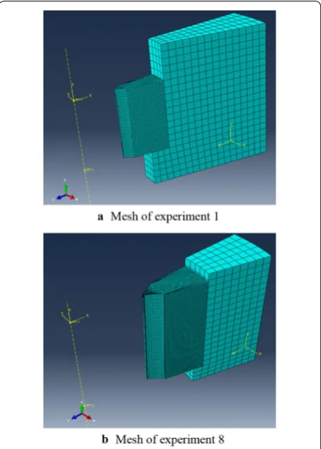
4.2 Meshing
Owing to the periodic symmetry of the ring gear and the box, in order to save computing resources and time, we intercept the 1/24 entity to build the model.
In ABAQUS, in order to ensure accurate calcula-tion, the inner ring gear is divided into relatively fine hexahedral meshes. In order to improve the calcula-tion efficiency, the box is divided into coarser meshes, and the unit type adopts the eight-node hexahedral lin-ear reduction integral unit C3D8R. The finite element model in experiment 1 is divided into 14380 units and 16899 nodes. The finite element model in experiment 8 is divided into 149265 units and 160243 nodes.
The material of the ring gear is 42CrMoA, the elastic modulus E = 206 GPa, and Poisson’s ratio ν = 0.3. The material of the gearbox is QT450, the elastic modu-lus E = 147 GPa, and Poisson’s ratio ν = 0.25. The 1/24 solid model is meshed, and the grids of the ring gear are thinned. The mesh is shown in Figure 2.
4.3 Contact and Boundary Conditions
The contact between the box and the ring gear is set to face-to-face contact. Since the prestress of the inner ring gear interference fit is the focus of this study, the mesh size of the inner ring gear is finer, so the inner surface of the box is set. For the main surface, we set the outer sur-face of the ring gear to the slave sursur-face and set the con-tact properties to “Hard Concon-tact” and “Penalty”.
There are two loading steps in the simulation. In the first step, a slight magnitude of interference is set for the touching of the ring gear and gearbox, namely, δ1 = 0.01 mm. In the second step, the magnitude of interference between the ring gear and gearbox is the actual magni-tude of interference. The two left and right sections are set as the periodic boundary condition, and the bottom of the ring gear touching the gearbox is set as the fixed boundary condition. The boundary conditions are shown in Figure 3.
4.4 Solution
The tangential prestress σt of the inner ring interference is equal to the difference between the internal stress σn and the residual stress σc. The tangential prestressed cloud diagram of the inner ring of experiment 1 and experiment 8 is shown in Figure 4.
5 Experiment
At present, an XRD is the most mature method for meas-uring the residual surface stresses of a structure [25, 26]. The XRD method is a method for non-destructive meas-urement of stress. The area of XRD is small, so the size of the measurement point is also small, and the stress on the surface of the device to be tested can be measured within a few micrometers to several tens of micrometers, and it is more suitable for on-site measurement. The distance of the crystal face will change when internal stresses occur in a specimen. The diffraction peak will move with it when diffraction occurs. In addition, the displacement distance is related to the amount of internal stresses. The internal stresses can be calculated based on the dis-placement distance of the diffraction peak. The LXRD X-ray diffractometer, shown in Figure 5, was used in the experiment.
In this study, residual stresses occur in the specimens, and thus the residual stresses of the ring gear should first be measured. Then, nine groups of gearboxes are heated, and the gearboxes and ring gears are assembled together using a shrinkage and expansion assembly method. Finally, the prestressing of the ring gear is measured
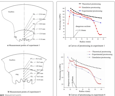
using XRD. Experiments 1 and 8 are used as examples. In experiment 1, the gearbox is heated for 3 h at a tempera-ture of 190 °C. In experiment 8, the gearbox is heated for 3 h at a temperature of 150 °C. Six measurement points are chosen in the specimen for experiment 1, and seven measuring points are chosen for the specimen in experi-ment 8. The measureexperi-ment points are shown in Figure 6.
6 Comparison of the Results
According to the theoretical analysis, the simulation using ABAQUS, and the experimental method, the the-oretical curves, simulation curves, and experimental curves of the prestressing of the ring gear in the interfer-ence fit for experiments 1 and 8 were chosen from the nine groups of experiments, and are shown in Figure 7.
Comparing the three curves in Figure 7, the errors in the simulation, experimental, and theoretical curves are less than 20%, and are attributed to postulated con-ditions, modeling, meshing, manufacturing error, and measurement errors.
Figure 3 Boundary conditions
Figure 4 Equivalent stress clouds of ring gear
Probe
Ring gear
Gearbox
Based on an analysis of the nine groups of experi-ments, the actual prestressing value of the ring gear in an interference fit has certain differences with the theo-retical value. The theotheo-retical values are the highest, the simulation values are the second highest, and the experi-mental values are the lowest. To facilitate the design and calculation, the theory of prestressing is revised, and the correction coefficient of prestressing of the ring gear in interference fit YIa is set when calculating the actual prestressing σ. As a result, the theoretical, simulation, and experimental values of the prestressing have differ-ent degrees of error. Their average values from the nine groups of experiments are first calculated, and compared with the theoretical value, and the correction coefficient of each experiment is then calculated. Finally, the cor-rection coefficient of the prestressing of the ring gear in the interference fit is obtained by calculating the aver-age value of nine groups of correction coefficient. As an
example of experiments 1 and 8, the calculated correc-tion coefficients are listed in Tables 3 and 4.
The correction factor YIa1 in experiment 1 is obtained through calculations as YIa1 = 0.893. The correction fac-tor YIa8 in experiment 8 is obtained through calculations as
YIa8 = 0.888.
The nine groups of correction factors are obtained using the same method. The average correction factor is then cal-culated as YIa = 0.891. Thus, the actual formula of the pre-stressing is as follows:
Eq. (6) can accurately calculate the prestressing of the inner ring gear in interference fit.
(6) σ =YIa·σt=0.891·
A1+B1· 1
r2
, Gearbox
ring
P6˖r= 23.0 mm
P5˖r= 20.5 mm
P4˖r= 18.0 mm
P3˖r= 15.5 mm
P2˖r= 13.0 mm
P1˖r= 11.0 mm
a Measurement points of experiment 1
Gearbox
ring
P7˖r= 59.5 mm P6˖r =54.5 mm
b Measurement points of experiment 8
P1˖r =33.0 mm P2˖r =36.5 mm P3˖r =39.5 mm P4˖r =44.5 mm P5˖r =49.5mm
Figure 6 Measurement points
10 12 14 16 18 20 22 24 -20
0 20 40 60 80 100 120 140 160 180
Experimental prestressing Simulation prestressing Theoretical prestressing
Prestressin
g
σt
(M
Pa
)
a Curves of prestressing in experiment 1
Radiusr(mm) dangerous sections rĬ13.16mm
Experimental prestressing Simulation prestressing Theoretical prestressing
Prestressing
σt
(M
Pa
)
Radiusr(mm)
b Curves of prestressing in experiment 8
dangerous sections rĬ
39
.4
9m
m
7 Correction Formula of the Tooth Root Flexural Fatigue Strength
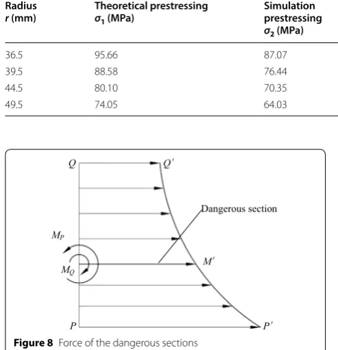
When the gearbox body interference connects with the ring gear, a meshing load from the planet gears occurs, as does a prestressing, which is σt in the interference fit. The prestressing σt, which affects the dangerous sections
MM′ of the gear, can be decomposed into two bending moments MP and MQ, and stress σM. The force of the dangerous sections MM′ is shown in Figure 8.
(7) MP=
rM
rP σdr=
rM
rP 0.891·
A1+B1· 1 r2
dr
=0.891·
A1·rM−B1· 1
rM
−
A1·rP−B1· 1
rP
=0.891·
A1·(rM−rP)−B1· 1 rM − 1 rP ,
where rQ = ri (radius of interface), rP = rr (reference radius of ring gear), rM= 2 tan(γS−α) , the tooth thickness of the dangerous section is S [27, 28], the normal loading angle is γ, and the pressure angle is α.
Eqs. (7), (8), and (9) can be simplified as follows: (8) MQ=
rQ
rM
σdr=
rQ
rM
0.891·
A1+B1·
1
r2
dr
=0.891·
A1·rQ−B1· 1 rQ
−
A1·rM−B1· 1 rM
=0.891·
A1·rQ−rM−B1·
1 rQ − 1 rM , (9) σM=
0.891·p·rQ2
r2Q−rP2
1+ r
2
P
rM2
,
(10) MP =0.891A1·
S
2 tan(γ −α) −rr
−0.891B1· 2 tan
(γ −α)
S − 1 rr , (11) MQ=0.891A1·
ri− S 2 tan(γ −α)
−0.891B1·
1 ri
− 2 tan(γ−α) S
, Table 3 Correction factors YIa1 in experiment 1
Radius
r (mm) Theoretical prestressingσ1 (MPa)
Simulation prestressing
σ2 (MPa)
Experimental prestressing
σ3 (MPa)
Average prestressing
σa (MPa)
Correction factor
YIa1 = σa/σ1
13.0 167.31 151.18 135.29 151.26 0.904
15.5 144.70 140.53 120.38 135.20 0.934
18.0 130.27 118.57 108.07 118.97 0.913
20.5 121.42 81.58 95.83 99.61 0.820
Table 4 Correction factors YIa8 in experiment 8 Radius
r (mm) Theoretical prestressingσ1 (MPa)
Simulation prestressing
σ2 (MPa)
Experimental prestressing
σ3 (MPa)
Average prestressing
σa (MPa)
Correction factor
YIa8 = σa/σ1
36.5 95.66 87.07 76.73 86.49 0.904
39.5 88.58 76.44 70.18 78.40 0.885
44.5 80.10 70.35 65.05 71.83 0.897
49.5 74.05 64.03 54.60 64.23 0.867
MP
MQ M
Ą
Dangerous section
P PĄ
Q QĄ
In a traditional gear bending fatigue strength calculation, when the ring gear is loaded, the bending stress of the dan-gerous sections of the single tooth is shown as below:
where the meshing load is pca.
Therefore, the bending stress produced by the two bending moments, MP and MQ, in the dangerous sections is shown below [29, 30]:
Finally, the correction formula of the tooth root flexural fatigue strength is obtained as
8 Conclusions
(1) Based on the method for calculating the prestress-ing of a thick cylinder in an interference fit, the ring gear is equivalent to a thick cylinder, and the mathematical model of prestressing of the ring gear in the interference fit is developed. The distribution rule of prestressing is inferred.
(2) Through theoretical calculation, simulation, and XRD measurements, nine groups of theoretical curves, simulation curves, and experimental curves
(12) σM=
0.891·p·ri2
ri2−r2 r
1+4r
2
r ·tan2(γ −α)
S2
.
(13)
σF0=
M
W =
pca·cosγ ·h
1×S2
6
= 6pca·cosγ ·h
S2 ,
(14) σI= MP−MQ
W =
MP−MQ
1×S2
6
= 5.346A1
S·tan(γ−α)−
21.384B1tan(γ−α)
S3
− 5.346A1(rr+ri)
S2 +
5.346B1
1
rr +
1
ri
S2 .
(15) σ′
F =σF0+σI+σM = KFtYFaYSa
bm +
5.346A1 S·tan(γ−α)
− 21.384B1tan(γ−α)
S3 −
5.346A1(rr+ri) S2
+ 0.891p·r 2 i ri2−rr2
1+ 4r
2
r ·tan2(γ −α) S2
+
5.346B1
1 rr +
1 ri
S2 ≤[σF].
for a prestressing of the ring gear in the interfer-ence fit are obtained. In the contrasting results of the three curves, the theoretical values are the high-est, the simulation values are second highhigh-est, and the experimental values are the lowest. To facili-tate the design, a theoretical calculation method of prestressing is adopted. The theoretical values are larger than the actual values, and thus the theoreti-cal values should be corrected. The correction fac-tor of prestressing of the ring gear in an interference fit was obtained using a contrast calculation. The correction factor YIa= 0.891 can be used to
accu-rately calculate the prestressing of the inner ring gear of the interference connection, and provides a theoretical method for calculating the prestressing of the spur gear ring.
(3) The stress of the ring gear in the meshing and the prestressing of the ring gear in the interference fit are composed. The final correction formula of the tooth root flexural fatigue strength is obtained. It provides theoretical guidance for practical design and production.
Authors’ Contributions
SY was in charge of the whole trial; SY and YJ wrote the manuscript; YM and TX assisted with sampling and laboratory analyses. All authors read and approved the final manuscript.
Authors’ Information
Shiping Yang, born in 1970, is currently a professor at Xiangtan University, China. He received his PhD degree from Xiangtan University, China, in 2014. His research interests include Gear dynamics and Spatial multiple conjugate transmission.
Yixing Ji, born in 1992, is currently working towards a master’s degree in engineering at School of Mechanical Engineering, Xiangtan University, China.
Yulin Mo, born in 1989, graduated from Xiangtan University, China, now is freelance.
Tianyu Xia, born in 1993, graduated from Xiangtan University, China, now is freelance.
Competing Interests
The authors declare that they have no competing interests.
Funding
Supported by Hunan Provincial Natural Science Foundation of China (Grant No. 2018JJ4006) and National Independent Innovation Demonstration Area Foundation of Changsha Zhuzhou Xiangtan (Grant No. 2018XK2302).
Received: 12 June 2018 Accepted: 7 August 2019
References
[2] German Institute of Standardization. DIN7190-2001 Rules for content, interference fits-calculation and design rules. Germany: German Institute of Standardization, 2001.
[3] Iglesias Miguel, Fernández Del Rincón Alfonso, De-Juan Ana Magdalena, et al. Planetary gear profile modification design based on load shar-ing modellshar-ing. Chinese Journal of Mechanical Engineering, 2015, 28(4): 810–820.
[4] X Y Xu, C C Zhu, H J Liu, et al. Load sharing research of planetary gear transmission system of wind turbine gearbox with flexible pins. Journal of Mechanical Engineering, 2014, 50(11): 43–49. (in Chinese)
[5] H Zhu, W Cheng, G H Jia, et al. Dynamic performance simulation on wind-power pitch planetary reducer. Journal of Central South University (Science and Technology), 2011, 10 (42): 3059–3065. (in Chinese) [6] Y J Jiang. The calculation of prestresses of the ring in the
thermal-coor-dinated gear. Inner Mongolia Science Technology and Economy, 2005, 5: 105–106. (in Chinese)
[7] Y Zou, F C Sun, W Q Wang, et al. Study on the relation between gear’s hole diameter and prestressing force in interference fit. Journal of Mechanical Transmission, 2003, 27(6): 41–42. (in Chinese)
[8] X Y Yan, C X Hong, H Liu, et al. Prestresses of the ring in the thermal-coordinated gear. Journal of Electric Power, 1994, 9(2): 6–10. (in Chinese) [9] C Q Zhu. Prestress analysis of keyless connection sleeve in hot assembly
based on ANSYS. Shandong Metallurgy, 2013, 35(4): 70–72. (in Chinese) [10] L Zhao, H C Wu, L M Zhao, et al. Prestressed mode analysis of planetary
gear train in automatic hydraulic transmission based on ANSYS. Mechani-cal Engineer, 2015, (08): 31–33. (in Chinese)
[11] G F Wang. Analysis of Influence of prestressing on interference fit of dump truck axle. Internal Combustion Engine & Parts, 2018, (16): 65–67. (in Chinese)
[12] H Y Kim, C Kim, W B Bae. Development of optimization technique of warm shrink fitting process for automotive transmission parts (3D FE analysis). Journal of Materials Processing Technology, 2007, 187: 458–462. [13] Rahman Seifi, Kaveh Abbasi. Friction coefficient estimation in shaft/bush
interference using finite element model updating. Engineering Failure Analysis, 2015, 57: 310–322.
[14] D S Hao, D L Wang. Finite-element modeling of the failure of interfer-ence-fit planet carrier and shaft assembly. Engineering Failure Analysis, 2013, 33: 184–196.
[15] Frederic Lanoue, Aurelian Vadean, Bernard Sanschagrin. Fretting fatigue strength reduction factor for interference fits. Simulation Modelling Prac-tice and Theory, 2011, 19: 1811–1823.
[16] X Q Xu, H H Zhao. Nonlinera FEM analysis of the contact stress on inter-ference fitting surfaces. Machine Design and Research, 2000, (1): 33–35. (in Chinese)
[17] Y Zhang, B McClain, X D Fang. Design of interference fits via finite ele-ment method. International Journal of Mechanical Sciences, 2000, 42: 1835–1850.
[18] L Amanan, K R Krishna, R Sriraman. Thermo-mechanical finite element analysis of a rail wheel. International Journal of Mechanical Sciences, 1999, 41: 487–505.
[19] Z B Wang. Research on lightweight design technology for large scale yaw and pitch gearboxes. Zhengzhou: Zhengzhou Machinery Research Insti-tute, 2012. (in Chinese)
[20] Z H Zhang, Z M Liu, H P Zhang, et al. The structural analysis of single planet carrier for yaw and pitch gearbox. Journal of Mechanical Engineer-ing, 2012, 48(6): 68–70. (in Chinese)
[21] L G Pu, G D Chen. Design of machinery. Beijing: Higher Education Press, 2012. (in Chinese)
[22] D Q Xu, R W Sun. The design, calculation, assembly and disassembly of the interference fit. Beijing: China Metrology Press, 1992. (in Chinese) [23] R J Teng, Y B Zhang, X J Zhou, et al. Mechanical properties and design
method of cylindrical interference fit. Journal of Mechanical Engineering, 2012, 48(13): 160–166. (in Chinese)
[24] Z X Liu, L Wang. Experimental design & data processing. Beijing: Chemical Industry Press, 2015. (in Chinese)
[25] T H Zhang, Y Wang, X F Fang, et al. Research status and development of residual stress detection and elimination methods. Journal of Netshape Forming Engineering, 2017, 9(5): 122–127. (in Chinese)
[26] Ines Fernandez Pariente, Mario Guagliano. Contact fatigue damage analy-sis of shot peened gears by means of X-ray measurements. Engineering Failure Analysis, 2009, 16: 964–971.
[27] Standardization Administration of the People’s Republic of China. GB/T 3480.5-2008 Rules for content, calculation of load capacity of spur and helical gears-part 5: strength and quality of materials. Beijing: China Standard Publishing House, 2008. (in Chinese)
[28] Vincent Savaria, Florent Bridier, Philippe Bocher. Predicting the effects of material properties gradient and residual stresses on the bending fatigue strength of induction hardened aeronautical gears. International Journal of Fatigue, 2016, 85(4): 70–84.
[29] Gabriel Marsh, Colin Wignall, Philipp R Thies, et al. Review and application of Rainflow residue processing techniques for accurate fatigue damage estimation. International Journal of Fatigue, 2016, 82(3): 757–765. [30] Mir Ali Ghaffari, Eric Pahl, Shaoping Xiao. Three dimensional fatigue