0 INTRODUCTION
By using closed shallow die forging (coining), it is possible to obtain complex geometry products with fine surface details of very small dimensions. According to [1] to [4], this process enters the micro-forming field. The micro-micro-forming processes are specific. They deviate from the macro deformation processes assumed on the basis of the similarity theory because they are subjected to the so-called “size effects”. The basis of the coining process was initially published by Bocharov et al. [5]. However, the analysis and models of the coining process, observed from the current state of the art, are more appropriate to the analysis of the classic forging processes. One scientific paper [6] deals with deformation of the surface layer and its asperities. These works completely exclude total deformation of the material and observe the effect of surface roughness on the friction coefficient in processes that involve high levels of contact pressure. Surface roughness affects the size of the contact surface between the tool and workpiece and affects the level of friction during the process. Surface roughness is certainly independent of the dimension of the workpiece itself. According to [7], the causes of size effects can be divided into the causes of density (compression), the causes of the part shape and the causes of the structure. If the density of
dislocations in the crystal lattice remains unchanged, the size effect is due to the fact that the reduction in the dimensions of the workpiece also reduces the volume of the material, which results in a reduction in the number of dislocations contained in the material. If the workpiece shape remains unchanged, the ratio of the workpiece surface to the volume changes with the reduction of the dimensions of the workpiece. In this case, the effect of the size is because certain properties are related to the surface (surface tension, heat, friction, surface crystalline grain, etc.), and some properties are related to the volume (weight, thermal capacity, the total number of crystalline grains, etc.). In the case of structural causes, surface roughness, geometry, dislocations, crystalline grain orientation, etc. contribute to the size effect.
The work of Ramaekers and Hoogenboom [8] deals with the analysis of the coining process in a fully closed die. The paper explains the determination of the coining force when considering ideal plastic material, which neglects the elastic properties of the material, and its flow stress is constant, i.e. does not depend on the true strain of the material. The paper published by Brekelmans et al. [9] examines the hardening of material. Although the material elastic properties of such material are neglected, the flow stress is no longer constant but depends on the true strain of the material.
Accuracy of Model Force Prediction in Closed Die Coining Process
Keran, Z. – Kondić, Ž. – Piljek, P. – Runje, B.
Zdenka Keran1,* – Živko Kondić2 – Petar Piljek1 – Biserka Runje1
1 University of Zagreb, Faculty of Mechanical Engineering and Naval Architecture, Croatia 2 University North, Croatia
In micro-forming processes, such as coining, the microstructure of the material and dimension scale of the coined geometry can have a substantial influence on the mechanism of material deformation. The influence of the grain size on the coining force and closed die filling is investigated experimentally, and a mathematical model for result prediction has been created according to the obtained experimental results. The material of the billet is 99.5 % aluminium, and the die geometry is relatively complex.
The presented mathematical model takes into account the influence of size effect on the material flow curve through die cavity geometry and estimates the final coining force and corresponding associated displacement of the tool. This enables a controlled influence of the grain size of the specimen material on forming force and tool displacement in the coining process and a reliable prediction of the final coining force and related tool displacement associated with a completely filled die cavity. To determine the accuracy of model force prediction, the experimental and modelled data were statistically analysed and graphically presented.
Keywords: micro-forming, coining, mathematical modelling, forging force
Highlights
• This paper presents research of the influence of the grain size of the specimen material on the coining force and closed die filling.
• The influence has been investigated experimentally, and a mathematical model for result prediction has been created. • The mathematical model takes into account the influence of size effect on the material flow curve.
The work of Ike and Plančak [10] classifies the coining process into the micro-forming area. In their paper, the analysis of the micro-geometry forming was done in the closed coining die with the assumed plane state of strain. Many papers are concerned with the study of the size effects in micro-forming, [7] and [11] to [13], and their influence on the various micro-forming processes, such as micro-indentation [14], micro-imprinting [15], micro-extrusion, [16] and [17], and the bulk forming processes of sheet metal, [18] and [19]. However, relatively few works deal with the coining process and the real problems of production, such as residual stress, elastic deformation and incomplete die filling, [1] to [3], [10] and [20] to [22], lubricant residues and surface damage [23], and tool development and manufacturing, [24] and [25]. That is why this process is still not researched and well-known, especially from the micro-forming point of view. By defining the crystalline grain size effect on elastic springback, die filling and the coining force, it is possible to control the process parameters, which will greatly contribute to the quality of the product. Some research work found a solution in FEM analysis of a material behaviour that provides very detailed access to stress-strain conditions [26].
This paper presents research on the influence of the grain size on the coining force and closed die filling. The influence has been investigated experimentally, and a mathematical model for result prediction has been created according to obtained experimental results. The mathematical model takes into account the influence of size effect on the material flow curve and estimates the final coining force and corresponding associated displacement of the tool.
To determine the accuracy of model force prediction, the experimental and modelled data were statistically analysed and graphically presented.
1 EMPIRICAL MODEL OF COINING FORCE
Important information in the coining process is knowledge about the forming force or force in which a completely filled die cavity is achieved. In scientific publications, [27] to [29], the coining force was estimated with similar empirical models, which can be reduced to Eq. (1):
F K k= k⋅ f1⋅A1, kf1= f
( )
ϕpl1 . (1)The forging factor Kk is, in this case, a
correction factor that includes the impact of the initial dimensions of the workpiece material, inhomogeneous deformation and friction between the
contact surfaces of the workpiece and the tool (forging die) [2]. Since the forging factor depends on the type of forging process and the geometry of the die, Eq. (1) can be understood as a general model for calculating the forging force. The empirically determined ranges of the forging factors, for the specific processes and complexity of the die cavity, are adapted from [27] to [29] and given in Table 1, which gives a relatively wide range of forging factors for a specific process. Together with a subjective estimation of the complexity of die cavity geometry this shows that the results are mostly based on the experience of engineers.
Table 1. Range of forging factors for the specific die cavity complexity
Die type Die cavity complexity Forging factor Half Closed
Simple 3 to 5 Complex 5 to 8 Very complex 8 to 12 Closed Simple 6 to 8
Complex 8 to 10 Flow stress expresses the mean value of the current flow stress in the workpiece, and it directly depends on the current true strain of the material. Since the coining process involves the impressing of complex die geometry into the workpiece material, the true strain is not uniform and changes depending on the observed working point, which makes it very difficult to determine the adequate value of the current strain and the current flow stress.
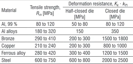
In this case, the current stress is estimated approximately on the basis of the upsetting test and the yield stress of the material or, as in the case of a correction factor, is determined by the empirically obtained values from [24], shown in Table 2. Deformation resistance in Table 2 is defined as a product of a forging factor, Kk, and flow stress, kf1, for the specimen material [2].
Table 2. Empirical determination of tensile stress
Material Tensile strength, R
m [MPa]
Deformation resistance, Kk∙ kf1
Half-closed die
1.1 Extended Empirical Model Depending on the Crystalline Grain Size
The empirical model of the coining force, Eq. (1), can be expressed depending on true strain as:
F
( )
ϕpl = p( )
ϕpl ⋅A( )
ϕpl . (2) The required acting pressure can be expressed as:p
( )
ϕpl =Kk( )
ϕpl ⋅kf( )
ϕpl . (3) Here kf(φpl) expresses the flow stress as afunction of a true strain φpl, i.e. the strain determined
by the given flow curve, and represents a specific deformation resistance as a material parameter, while the Kk(φpl)is a strain-dependant forging factor which
represents a correction function that corrects the effect of contact friction and the influence of die geometry and workpiece dimensions and shapes.
When coining in identical conditions (equal die, equal workpiece dimensions, equal friction conditions, equal deformation velocity, etc.) for which the only difference is the crystal grain size of the workpiece, the change in the effective coining (forming) pressure depends entirely on the change in material resistance to deformation, i.e. the material flow curve, and is independent of the forging factor:
p
(
ϕpl,d)
=Kk( )
ϕpl ⋅kf(
ϕpl,d)
. (4)Therefore, the forging factor (Kk) can be
considered constant for the individual true strain of the material. In the case of true strain at which the die is fully filled, the correction function value corresponds to the empirically determined forging factor (Table 1). By incorporating the expanded Hall-Petch expression from [20] and [30] into Eq. (4), the next formulation for forging force is obtained, in which the forging force depends on true strain and the crystalline grain size:
F d K A
M K d
pl k pl pl
or R pl hp pl
ϕ ϕ ϕ τ ϕ ϕ β ,
(
)
=( )
⋅( )
⋅ ⋅( )
+( )
⋅ ⋅ − ± 12 .. (5)
In Eq. (5), Mor is the average orientation of the
crystalline grid of all grains. Lorentzen et al. [31] have experimentally demonstrated that the metal with the FCC structural grid orientation factor has Mor about
2.6. τR is the critical shear stress of a crystalline grain
[31]. Khp is interpreted as the resistance of the grain
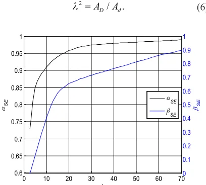
boundary to deformation (parameter from a Hall-Petch model), and d is the size of the crystalline grain. Parameters αSE and βSE are determined on the basis
of the findings of [20] and [30]. The size factor (λ) is
obtained from the diagram on Fig. 1, in which size factor is defined as:
λ2 =
A AD/ d. (6)
0 0.1 0.2 0.3 0.4 0.5 0.6 0.7 0.8 0.9 1
βSE
0 10 20 30 40 50 60 70
0.6 0.65 0.7 0.75 0.8 0.85 0.9 0.95 1 λ
αSE
αSE βSE
Fig. 1. αSE and βSE size parameters dependent on the size factor λ
The true strain is determined by the volume of the impressed die or volume of squeezed out material as:
p
( )
ϕpl =V V V/(
− IM SQ/)
. (7)The shear flow stress τR and the grain boundary
resistance Khp are the parameters of the classical
Hall-Petch model and can be determined by using a classical experiment of flow curves recording with samples of different crystalline grain size. It is necessary to know the size of crystalline grain samples and to use samples of at least two different crystalline grain sizes.
Dependence of the current (contact) surface and the size factor on true strain can be estimated by knowing the geometry of the die cavity. By knowing the size factor, it is possible to determine the effect parameters of the size (αSE and βSE).
2 PLAN OF EXPERIMENT AND EXPERIMENT IMPLEMENTATION TECHNIQUE
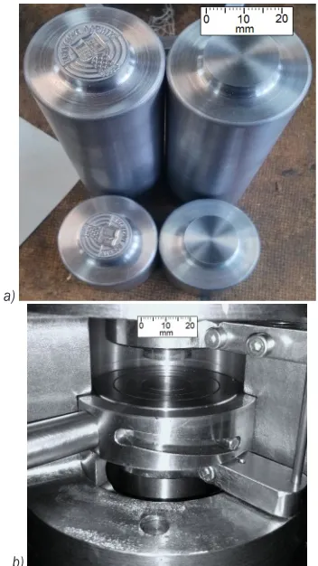
The aim of the experimental research is to verify the proposed model of a coining process that gives the force dependence on the crystalline grain size. The closed tool type consists of three main parts: the upper die, the lower die, and the holder. The upper and lower dies perform axial compression on the workpiece and map the die geometry, while the holder prevents radial expansion of the workpiece.
of the forehead of the die. Filling the tool cavity and forming the geometry of the product are done. During the forming process, it is desirable to achieve the same deformation of the material in all segments of the die cavity, and it is necessary to provide free separation of the workpiece from the tool cavity after the deformation process is completed. Therefore, to obtain the final product shape, it is necessary to find a compromise between the design and the imposed geometric constraints. The final geometry of the die cavity comes from the experience and the trial-and-error method.
a)
b)
Fig. 2. a) Upper and lower die and b) their position in a holder
Because of the use of a hydraulic press with a continuous force measurement, the forming force was selected as the first input variable of the experiment, i.e. the first influencing factor. The final force levels are 55 kN, 100 kN, 150 kN, and 200 kN. The second input variable was the crystal grain size of the test sample. The output variables are total tool displacements. The plan of the experiment is given in Table 3. After metallographic sample preparation (cutting, polishing and etching), the workpiece grain size is determined using an optical microscope (Olympus GX51) and chart comparison methods
according to the ASTM standard. The average grain size is obtained as a mean value of at least five grain size measurements on the radial and axial planes of the workpiece. Samples of microstructures, on workpiece radial and axial sections, for different grain sizes are shown on Fig. 3.
Table 3. Plan of the experiment (number of samples for specific grain size and final forming force)
Grain size [μm]
25 50 90
Number of measurements
Final force [kN]
55 5 5 5
100 5 5 5
150 5 5 5
200 5 5 5
200 μm 200 μm
200 μm 200 μm
200 μm 200 μm
Fig. 3. Workpiece microstructures a) and b) 25 μm, c) and d) 50 μm, e) and f) 90 μm, for radial and axial section, respectively
2.1 Experimental and Model Results
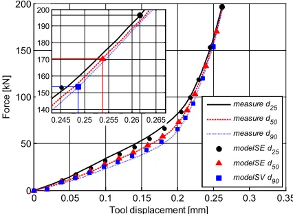
very close to the maximum contact surface, the results obtained through Eqs. (1) to (7) and experimental measurements are very well matched.
Although the experimental and model results are very well matched, the point at which the engraving cavity is completely filled can be determined only with the visual evaluation of the forged geometry at a certain forging (coining) force. Therefore, Figs. 5 and 6 show a parallel view of the geometry of the coin detail for different crystalline grain size that is obtained with the force of 150 kN and 200 kN.
From the diagram in Fig. 4 and the visual comparison of the geometry in Figs. 5 and 6, it is apparent that the dimensional model satisfactorily describes the coining and gives a very good estimation of the final forging force.
0 0.05 0.1 0.15 0.2 0.25 0.3 0.35
0 50 100 150 200
Tool displacement [mm]
Fo
rce
[kN
]
measure d25 measure d50 measure d90 modelSE d25 modelSE d50 modelSV d90 0.245 0.25 0.255 0.26 0.265
140 150 160 170 180 190 200
Fig. 4. Comparison of a model with size effects (SE) and experimental results
3 STATISTICAL ANALYSIS OF EXPERIMENTAL AND MODEL RESULTS
Modelled and experimental data for crystalline grain size d25, d50, and d90 were analysed using Bonnet’s and Levene’s tests. These tests are used to verify the homogeneity of variances. They are more robust than tests when normality is not assumed [32].
The test was performed on a sample of 30 measurement points (forces up to 200 kN) for each grain size. The results are presented in Table 4.
Table 4. Bonnet’s and Levene’s test
Bonett’s test Levene’s test
d25 P = 0.817 P = 0.745 d50 P = 0.832 P = 0.846 d90 P = 0.805 P = 0.816
Because all the p-values are greater than a reasonable choice of α (α = 0.05), there is no significant evidence to reject the null hypothesis stating that the variances are equal. This data does not provide enough evidence to claim that modelled and experimental data for all crystalline grain sizes have unequal variances.
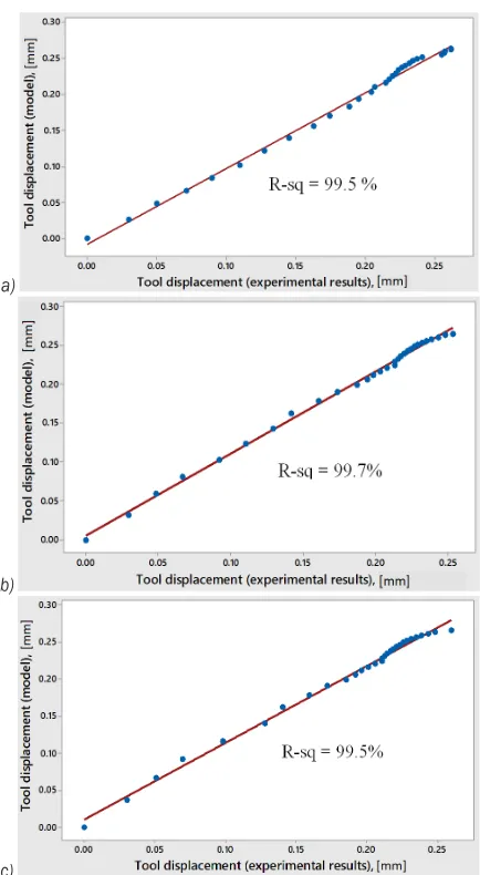
Modelled data and experimental data were also compared using the quantile-quantile plot (q-q plot). Results are presented in Fig. 6. The q-q plot graphical technique shows that modelled and experimental data for all crystalline grain sizes come from populations with a common Weibull distribution.
The high values of coefficients of determination (R-squared) show that the model fits the observed data
Fig. 5. Geometry details of the coin with different crystalline grain size a) 25 μm, b) 50 μm, c) 90 μm, obtained with 150 kN forging force
well, i.e. the relationship between the modelled data and the observed data is fairly strong.
a)
b)
c)
Fig. 6. The Quantile-Quantile q-q plot for crystalline grain size a) 25 μm, b) 50 μm, c) 90 μm
4 CONCLUSIONS
Since the coining process is regularly linked to large-scale and mass production and the size of the crystal grain of the workpiece affects the required forging force, it makes possible to achieve the same or satisfactory quality of the final product with significant energy savings if this forging force can somehow be predicted and optimized.
The influence of the size effects on the flow curve, and thus on the flow stress, is determined by the extended Hall-Petch model, which requires the knowledge of the size factor parameters (αSE and βSE).
The size factor parameters are determined by data based on the die size factor (λ).
The final results of a model are the forging force and the tool displacement in which the die cavity is completely filled, and the coining process is completed. The model was verified experimentally by the collected data from the force sensor and displacement sensor during the workpiece compression for all three different sizes of the crystalline grain (25 μm, 50 μm, 90 μm) and by visual comparison of the forged details. Collected experimental data and model results are shown in curves in the displacement–force diagram. Statistical analysis shows that modelled and experimental data for each crystalline grain size have unequal standard deviations and come from populations with a common distribution. The high values of coefficients of determination (R-squared) show that the model fits the observed data well, i.e. the relationship between the modelled data and the observed data is fairly strong.
Further research should include a variety of material investigations and model testing on different material types.
5 NOMENCLATURES
A current contact surface [mm²] A1 final workpiece surface [mm²] Ad surface of crystalline grain [mm²]
AD surface of impressed die [mm²]
d size of crystalline grain [μm] F forging/coining force [kN] kf current flow stress [MPa]
kf1 final flow stress [MPa]
Kk forging factor (empirically determined)
Khp resistance of grain boundaries [MPa]
Mor mean crystal orientation factor
p acting pressure [MPa]
P statistical probability value [%] V workpiece volume [mm³] VIM/SQ volume of impressed die [mm³]
α statistical significance level
αSE, βSE size effect parameters
φpl current true strain
φpl1 final true strain
λ size factor
τR critical shear stress [MPa]
6 REFERENCES
[1] Keran, Z., Math, M., Grizelj, B. (2011). Experimental and
approach. Tehnicki vjesnik -Technical Gazette, vol. 18, no. 4, p. 505-510.
[2] Piljek, P. (2017). Closed Die Coining Model Based on Grain
Size. PhD Thesis, University of Zagreb, Faculty of Mechanical
Engineering and Naval Architecture, University of Zagreb, Zagreb.
[3] Keran, Z., Math, M., Piljek, P. (2012). FEM analyses of friction
coefficient in open die coining process of different grain sizes.
Journal of Material Sciences and Engineering, vol. 1, no. 1, p.
1-4, DOI:10.4172/2169-0022.1000105.
[4] Wang, G., Zheng, W., Wu, T., Jiang, H., Zhao, G., Wei, D., Jiang,
Z. (2012). A multi-region model for numerical simulation
of micro bulk forming. Journal of Materials Processing
Technology, vol. 212, no. 3, p. 678-684, DOI:10.1016/j.
jmatprotec.2011.05.023.
[5] Bocharov, Y., Kobayashi, S., Thomsen, E. (1962). The
mechanics of the coining process. Journal of Engineering for
Industry, vol. 84, no. 4, p. 491-501, DOI:10.1115/1.3667550.
[6] Bay, N., Wanheim, T. (1976). Real area of contact between a
rough tool and a smooth workpiece at high normal pressures.
Wear, vol. 38, no. 2, p. 225-234,
DOI:10.1016/0043-1648(76)90072-7.
[7] Vollertsen, F. (2011). Size effects in micro forming. Key
Engineering Materials, vol. 473, p. 3-12, DOI:10.4028/www.
scientific.net/KEM.473.3.
[8] Ramaekers, J.A.H., Hoogenboom, S. (1985). The prediction
of tool pressures in coining. Advances in Manufacturing
Technology - 2nd IMC Conference Proceedings, vol. 383, p.
137-140.
[9] Brekelmans, W.A.M., Mulders, L.H.G., Ramaekers, J.A.H., Kals,
J.A.G. (1988). The coining process: analytical simulations
evaluated. CIRP Annals, vol. 37, no. 1, p. 235-238,
DOI:10.1016/S0007-8506(07)61625-4.
[10] Ike, H., Plancak, M. (1998). Coining process as a means
of controlling surface microgeometry. Journal of Materials
Processing Technology, vol. 80-81, p. 101-107, DOI:10.1016/
S0924-0136(98)00101-0.
[11] Fu, M.W., Chan, W.L. (2014). Size effects in micro scaled
plastic deformation. Micro-scaled Products Development via
Microforming. Springer-Verlag, London,
DOI:10.1007/978-1-4471-6326-8_2.
[12] Xu, J., Zhu, X., Shan, D., Guo, B., Langdon, T.G. (2015). Effect
of grain size and specimen dimensions on micro-forming of
high purity aluminum. Materials Science and Engineering: A,
vol. 646, pp. 207-217, DOI:10.1016/j.msea.2015.08.060.
[13] Ghassemali, E., Tan, M.-J., Wah, C.B., Lim, S.C.V., Jarfors,
A.E.W. (2015). Effect of cold-work on the Hall-Petch breakdown
in copper based micro-components. Mechanics of Materials,
vol. 80, p. 124-135, DOI:10.1016/j.mechmat.2014.10.003.
[14] Chen, B., Wang, L. (2013). Micro-plasticity constitutive
model taking account of size effects for pure aluminum by
microindentation. Journal of Wuhan University of Technology -
Materials Science Edition, vol. 28, no. 6, p. 1101-1106.
[15] Gao, Z., Peng, L., Yi, P., Lai, X. (2013). An experimental
investigation on the fabrication of micro/meso surface
features by metallic roll-to-plate imprinting process. Journal
of Micro and Nano-Manufacturing, vol. 1, no. 3, p. 31-40,
DOI:10.1115/1.4024985.
[16] Ghassemali, E., Tan, M.-J., Jarfors, A.E.W., Lim, S.C.V. (2013).
Optimization of axi-symmetric open-die micro-forging/extrusion
processes: An upper bound approach. International Journal
of Mechanical Sciences, vol. 71, p. 58-67, DOI:10.1016/j.
ijmecsci.2013.03.010.
[17] Hsia, S.-Y. (2013). Optimization of microextrusion preforming
using Taguchi method. Mathematical Problems in Engineering,
p. 9-10, DOI:10.1155/2013/305797.
[18] Merklein, M., Allwood, J.M., Behrens, B.-A., Brosius,
A., Hagenah, H., Kuzman, K., Mori, K., Tekkaya, A.E., Weckenmann, A. (2012). Bulk forming of sheet metal.
CIRP Annals, vol. 61, no. 2, p. 725-745, DOI:10.1016/j.
cirp.2012.05.007.
[19] Chan, W.L., Fu, M.W. (2013). Meso-scaled progressive forming
of bulk cylindrical and flanged parts using sheet metal.
Materials & Design, vol. 43, p. 249-257, DOI:10.1016/j.
matdes.2012.07.004.
[20] Kim, G.-Y., Koç, M., Ni, J. (2008). Experimental and numerical
investigations on microcoining of stainless steel 304. Journal
of Manufacturing Science and Engineering, vol. 130, no. 4, p.
041017-1/6, DOI:10.1115/1.2953235.
[21] Uhlmann, E., König, C., Ziefle, A., Prasol, L. (2012). Coining of
micro structures with an electromagnetically driven tool. 5th
International Conference on High Speed Forming, p. 45-52,
DOI:10.17877/DE290R-4855.
[22] Nam, J.S., Lee, S.W., Kim, H.S. (2014). Investigations into
the size effect on plastic deformation behavior of metallic
materials in microcoining process. International Journal of
Precision Engineering and Manufacturing, vol. 15, no. 1, p.
5-11, DOI:10.1007/s12541-013-0300-y.
[23] Zhong, W., Liu, Y., Hu, Y., Li, S., Lai, M. (2012). Research on the
mechanism of flash line defect in coining. The International
Journal of Advanced Manufacturing Technology, vol. 63, no.
9-12, p. 939-953, DOI:10.1007/s00170-012-3952-3.
[24] Milutinović, M., Movrin, D., Pepelnjak, T. (2012). Theoretical
and experimental investigation of cold hobbing processes in
cases of cone-like punch manufacturing. International Journal
of Advanced Manufacturing Technology, vol. 58, no. 9-12, p.
895-906, DOI:10.1007/s00170-011-3457-5.
[25] Hobemägi, A. (1994). Hobbing: A renewed method for
producing moulds and dies. Journal of Material Processing
Technology, vol. 42, no. 4, p. 421-430,
DOI:10.1016/0924-0136(94)90147-3.
[26] Pepelnjak, T., Milutinović, M., Plančak, M., Vilotić, D.,
Randjelović, S., Movrin, D. (2016). The influence of extrusion
ratio on contact stresses and die elastic deformations in
the case of cold backward extrusion. Strojniški vestnik -
Journal of Mechanical Engineering, vol. 62, no. 1, p. 41-50,
DOI:10.5545/sv-jme.2015.3051.
[27] Kalpakjian, S., Schmid, S.R. (2013). Manufacturing
Engineering and Technology. Pearson Education Centre, London.
[28] Groover, M.P. (2010). Fundamentals of Modern Manufacturing:
Materials Processes, and Systems. John Wiley & Sons, New York.
[29] Tschatsch, H. (2006). Metal Forming Practise: Processes,
Machines, Tools. Springer-Verlag, Berlin, Heidelberg,
[30] Kim, G.-Y., Ni, J., Koç, M. (2007). Modeling of the size effects on the behavior of metals in microscale deformation processes.
Journal of Manufacturing Science and Engineering, vol. 129,
no. 3, p. 470-476, DOI:10.1115/1.2714582.
[31] Lorentzen, T., Leffers, T., Clausen, B. (1998). Polycrystal
models and intergranular stresses. Proceedings of
International Symposium on Metallic Material Science, p. 345-354.
[32] Mathews, P.G. (2004). Design of Experiments with MINITAB.