International Journal of Engineering
J o u r n a l H o m e p a g e : w w w . i j e . i rExact Modeling and Simulation of Saturated Induction Motors with Broken Rotor
Bars Fault using Winding Function Approach
M. Ojaghi* a, M. Sabouria, J. Faizb, V. Ghorbanianb
a Department of Electrical Engineering, Faculty of Engineering, University of Zanjan, Zanjan, Iran
b Center of Excellence on Applied Electromagnetic System, School of Electrical and Computer Engineering, University of Tehran, Tehran, Iran
P A P E R I N F O
Paper history: Received 17 August 2013
Received in revised form 22 September 2013 Accepted 26 September 2013
Keywords:
Induction motors Broken bar fault Magnetic saturation Modeling
Computer simulation
A B S T R A C T
Winding function method (WFM) provides a detailed and rather simple analytical modeling and simulation technique for analyzing performance of faulty squirrel-cage induction motors (SCIMs). Such analysis is mainly applicable for designing on-line fault diagnosis techniques. In this paper, WFM is extended to include variable degrees of magnetic saturation by applying an appropriate air gap function and novel techniques for estimating required saturation factor and angular position of the air gap flux density. The resultant saturable winding function method (SWFM) is properly applied to analyze SCIMs with broken rotor bars and to identify the saturation effect on the related fault indexes. Comparing simulation results to the corresponding experimental ones show higher accuracy of the SWFM. This means that more precise fault diagnosis techniques can be designed by using the proposed saturable modeling technique.
doi:10.5829/idosi.ije.2014.27.01a.10
NOMENCLATURE
Bai Air gap flux density next to any rotor mesh i ik Current of the rotor mesh k , k=1, 2, …, R Bcn Cosine component of nth space harmonic of the air gap flux density J Inertia moment of the rotor and mechanical load Bsn Sine component of nth space harmonic of the air gap flux density Ksat Saturation factor
Bn Amplitude of nth space harmonic of the air gap flux density l Stack length
g-1 Inverse air gap function Lii Self inductance of the circuit i
gs Fictitious air gap function in the presence of saturation Lij Mutual inductance between the circuits i and j
g' Mean value of gs lb Leakage inductance of the rotor bars
g0 Effective air gap length of the unsaturated machine le Leakage inductance of the rotor end ring between two adjacent bars
nx Turn function of the x phase (mesh) ia , ib, ic Stator phase currents
Ny Winding function or modified winding function of the y phase (mesh) Greek Symbols
P Number of pole pairs αn Phase angle of the n
th space harmonic of the air gap
flux density
R Number of rotor bars (meshes) αi Angle of the center of the rotor bar i
Rs Resistance of the stator windings θr Rotor angular position
Rrb Resistance of the rotor bars φ Angle in the stator stationary reference frame Rre Resistance of the rotor end ring between two adjacent bars φf Angular position of a zero crossing point of the air gap flux density
r Air gap mean radius ρ Peak value of fluctuation of gs
s Slip μ0 The air magnetic permeability
Te Induced torque
*Corresponding Author Email:[email protected] (M. Ojaghi)
1. INTRODUCTION
Any factor disturbing electrical, magnetic and/or mechanical symmetry of squirrel cage induction motor (SCIM) can generate undesirable variations of the motor quantities. If these variations are intensified, the motor operation deteriorates or it stops [1-4]. The air gap magnetic flux density is a dominant factor of the motor behavior such that all its quantities including current, torque and power directly depend on this factor [5-11], while in turn; the air gap magnetic flux density is directly affected by the motor core magnetic saturation [9, 12]. Normally, the rotor broken bars in high power electrical motors lead to high local saturation around the breakage part [9]. The local saturation produces backward variations in the air gap flux density and this reflects over all motor variables [1, 13]. On the other hand, precise diagnosis of the fault degree is essential in a proper repair and maintenance process. Meanwhile, use of a precise model, which follows real behavior of the motor with suitable accuracy, can be taken into account as the first stage in the fault diagnosing procedure. Therefore, including the motor core saturation as major factor in the faulty motor behavior is unavoidable [14, 15]. To this end, many attempts have been so far made to deal with this problem; each has its merits and drawbacks.
Application of magnetic harmonic functions is well-known as a procedure for applying core saturation to the motor model [16, 17]. In fact, core saturation is applied analytically to the first and third harmonics of the air gap flux. The advantage of this method is that it does not need to evaluate the inductances considering all harmonics present. In spite of this, efficiency of the model for faulty motor has not been investigated. Magnetic equivalent circuit is another analytical model which is applicable for simulating faulty SCIMs. Core saturation with proper precision has been included in this model and a good agreement between the experimental and simulation results has been achieved [18, 19].
Winding function method (WFM) offers an analytical model widely used to model and simulate the faulty SCIMs due to its rather simple implementation [20-23]. First, linear model has been presented and reluctance variations of the flux path due to the saturation has been ignored [24]. This model has not been recommended to predict the SCIM behavior under the rotor broken bars fault which directly depends on the core saturation level. In spite of this, the linear model has been used for modeling the SCIM with the rotor broken bars fault in different modes, including line-start mode [24] and inverter-fed mode [25]. But, the obtained values of the fault indexes are not applicable because the core saturation has not been applied [13]. In fact, core saturation is the main factor in determining the broken bar fault indexes amplitude [26]. Reference [27] has shown that the difference between the non-saturated and
saturated models regarding fault index amplitudes could be as much as 15 dB.
The first attempt to include core saturation effect in the WFM has been proposed by [28]. The basis of this saturable WFM (SWFM) is application of a saturation factor (Ksat) to the linear model and varying the motor
inductances in different operating points. The saturation factor has been determined using the air gap voltage fundamental harmonic amplitude, which depends on the rotation speed of the air gap flux density as well as its amplitude, while the saturation degree depends only on the flux density amplitude. To modify the previous SWFM, the method introduced by [29] can be used. However, the broken rotor bars disturb the flux density distribution in the air gap and cause the SWFM introduced [29] to track the air gap flux density incorrectly.
In this paper, modifications are made to the previous SWFM in order to make it applicable to simulate SCIMs with broken rotor bars fault. To do so, the rotor meshes are used as the air gap flux samplers. The flux-linkages of the rotor meshes, which are calculated in every simulation step, are used to estimate the air gap flux density distribution around the air gap. Then, Fourier series analysis is used to determine the space harmonics of the air gap flux density, including fundamental harmonic amplitude (B1) and its phase angle (α1). B1 is
used to determine Ksat properly and α1 is utilized to track
the air gap flux density. Therefore, a modified version of the SWFM obtains, whose accuracy proves by comparing magnetization characteristics determined through simulation and experiments. Then, using both the modified SWFM and the normal WFM, the performance of SCIM with broken rotor bars is simulated. By comparing the results, impacts of the magnetic saturation on the faulty SCIMs performance and their fault indexes will be clear. Comparisons are also made by experimental results, which confirm the higher accuracy of the proposed SWFM. This means that more precise fault diagnosis techniques can be designed using the proposed saturable modeling technique.
2. SATURABLE WINDING FUNCTION METHOD FOR
MODELING SCIMs
] [ ] ][ [ ]
[ s s s dt s
d I R
V = + y (1)
] [ ] ][ [ ] 0
[ r r dt r
d I
R + y
= (2) dt d J L T e
T - = w (3)
dt dqr
w= (4)
where:
T ca bc ab s v v v
V] [ ]
[ = (5)
T c b a s i i i
I ] [ ]
[ = (6)
T R r i i i
I ] [ ... ]
[ = 1 2 (7)
] ][ [ ] ][ [ ]
[ys = Lss Is + Lsr Ir (8)
] ][ [ ] ][ [ ]
[yr = Lrs Is + Lrr Ir (9)
] [ ] [ ] [ 2 1 ] [ ] [ ] [ 2 1 ] [ ] [ ] [ 2 1 ] [ ] [ ] [ 2 1 r r rr T r s r rs T r r r sr T s s r ss T s e I L I I L I I L I I L I T q q q q ¶ ¶ + ¶ ¶ + ¶ ¶ + ¶ ¶ = (10) ú ú ú û ù ê ê ê ë é = s s s s R R R R 0 0 0 0 0 0 ] [ (11) ú ú ú ú ú ú û ù ê ê ê ê ê ê ë é + -+ -+ -+ = ) ( 2 0 ) ( 2 0 0 ) ( 2 0 ) ( 2 ] [ re rb rb re rb rb rb re rb rb rb rb re rb r R R R R R R R R R R R R R R R K K M K M M M M K K K (12)
As seen, various self/mutual inductances of the stator phases and/or the rotor meshes, i.e. elements of the inductance matrices [Lss], [Lsr], [Lrs] and [Lrr], and their
derivatives versus the rotor position are the most important parameters within the dynamic equations. Some of these inductances depend on the rotor position. So, by rotating the rotor, they must be updated at each simulation step. According to the winding function or modified winding function theory [22], these inductances are calculated as follows:
ò
-=m 2p j
0
1n N d
g l r
Lxy o x y (13)
where x and y represent any phase of the stator (a, b or c) or any mesh of the rotor (1 to R). For uniform air gap machine, Ny is the winding function of the y circuit, but in
the case of the non-uniform air gap machine, it is the modified winding function of the y circuit. In the latter case, the modified winding function guarantees the
equality: Lxy=Lyx for any x and y circuits [22]. Therefore,
it can be realized that [Lrs] = [Lsr]T. A technique to
evaluate the impacts of the rotor bars skewing on the elements of the matrix [Lsr] has been presented in [21]
and used in the simulation procedure. Leakage inductances must be added to the self-inductances and some mutual-inductances obtained from (13) as follows [30]: ú ú ú û ù ê ê ê ë é + + + = ls aa bc ac bc ls aa ab ac ab ls aa ss l L L L L l L L L L l L L ] [ (14) ú ú ú ú ú ú û ù ê ê ê ê ê ê ë é + + -+ + -+ + = ) ( 2 3 2 1 31 2 23 ) ( 2 21 1 13 12 ) ( 2 ] [ 22 11 e l b l L R L R L b l R L L R L b l L e l b l L b l L b l R L L b l L e l b l L rr L RR L M M M M M M L L L L L (15)
Saturation of the magnetic material causes its reluctance to be increased against the machine's flux. Similar increase of the reluctance can be achieved by a proportional increase in the air gap length along the main flux path [14, 28, 29]. Anywhere within the core material, reluctance increases due to the saturation depends on the exact value of the flux density, but independent of the flux direction. Thus, it is expected that the fictitious air gap length fluctuates a complete cycle every half cycle of the flux density distribution around the air gap. Assuming a sinusoidal form for this fluctuation [14], the following relation (16) satisfies the mentioned requirements [29]:
))] ( 2 cos( 1 [ ) , ,
( f sat f
s K g P
g jj = ¢ -r j-j (16)
where g' and ρ are determined as follows:
2 3 0 + = ¢ sat sat K K g g (17) sat sat K K 3 ) 1 ( 2 -= r (18)
Ksat is defined as the ratio of the fundamental components
of the air gap voltage for the saturated and unsaturated conditions [14, 28, 29]. Replacing the inverse of (16) in (13), using modified winding function theory, assuming the turn functions have only step variation in the center of the slots and determining the indefinite integrals, exact analytic equations are obtained for various inductances. Then, differentiating the equations versus the rotor position θr, exact analytic equations are also obtained for
the derivatives of the inductances. The equations are functions of Ksat and φf, and they are used to include the
3. DETERMINING Ksat AND φf IN FAULTY SCIM
A simple technique to determine φf has been offered by
[29], but in the faulty SCIM, the air gap flux density distribution disturbs and leads to error in the use of that technique. Also, Ksat has been determined using the air
gap voltage, which depends on the rotation speed of the air gap flux as well as its amplitude, while the saturation degree depends only on the flux density amplitude [29]. This causes difficulty when applying the model to variable-speed drive systems, as the air gap voltage before saturation is no more a constant, but varies by the reference speed variation. The aim of this section is to resolve these problems.
In simulation of a SCIM using the WFM or SWFM, flux-linkages of all rotor meshes are evaluated at any step. According to (9), these flux linkages have contributions from all the stator phases and rotor meshes. Since any rotor mesh consists of only one turn, these flux-linkages are the total fluxes passing through the meshes. Considering the short air gap length and ignoring some stator flux leakages that return from the air gap and never reach the rotor core, the flux density next to any rotor mesh i within the air gap can be estimated as:
A
Bai=yi (19)
where A is the area above the mesh in the air gap:
R rl
A=2p (20)
Therefore, an estimation of whole air gap flux density distribution is determined at any simulation step. Then, the space harmonics of the air gap flux density is determined by Fourier series analysis as follows:
] ) cos( ) [cos( 1
) sin( 1
) sin( ) ( 1
1 1
1 2 0
1
å
ò
å
ò
= +
=
-= = =
+
R
i ai i i
R i
ai sn
nP nP
B np
d nP B
d nP B
B
i i
a a
p
a a p
a a a
p a a p
(21)
å
å ò
ò
= +
=
-=
= =
+
R
i ai i i
R
i ai cn
nP nP
B np
d nP B
d nP B
B
i i
1 1
1 2 0
)] sin( ) [sin( 1
) cos( 1
) cos( ) ( 1
1
a a
p
a a p
a a a
p
a a p
(22)
Then, the phase angle and amplitude of the space harmonics are calculated as follows:
) ( tan 1
cn sn
n B
B
-=
a (23)
2 2
sn cn
n B B
B = + (24)
The air gap flux density distribution of a SCIM with two broken rotor bars at a simulation step is determined
Figure 1.Estimated air gap flux density (__) and its fundamental
space harmonic (---) for a SCIM with two broken rotor bars.
Figure 2. Time variation of φfof the SCIM with two broken
rotor bars
using (19), and its fundamental space harmonic is calculated using (21)-(24). Figure 1 shows the results where distortion of the flux density due to the fault is obvious. Having the phase angle of the fundamental harmonic, φf is estimated as:
P P
r
f q a1 2p
j = + - (25)
Figure 2 shows the variation of φf (between -π to +π)
versus time obtained during simulation of the SCIM with two broken rotor bars. Constant slope of increase of φf
indicates constant speed of the air gap flux density, i.e. the synchronous speed. Using the amplitude of the space fundamental harmonic of the air gap flux density, Ksat is
obtained as follows:
0 1 B
B
Ksat= (26)
Assuming all the fluxes are concentrated within the teeth, B0 is related to the knee-point flux density (Bkp) of the
core material as:
w w B
B t
kp
=
0 (27)
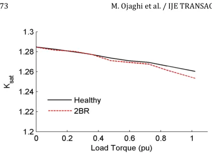
Figure 3 shows the variation of Ksat versus the load
torque of the healthy and faulty (with two broken rotor bars) SCIMs obtained using simulations. As seen, Ksat
Figure 3.Variation of Ksat versus load torque in the healthy and
faulty (with two broken rotor bars) SCIMs
leads to decrease of the air gap flux and saturation degree. For the load torque above 0.7 pu, decrease of Ksat in the
faulty SCIM is more than that in the healthy SCIM. This indicates that the fault causes decreasing the amplitude of the space fundamental harmonic of the air gap flux density in the mentioned load torque range. However, at the no-load and light load conditions, Ksat curves obtained
for healthy and faulty SCIMs are almost coinciding. This is because the rotor bars have small currents at light load conditions, such that the currents of the broken bars diminish. All the simulation results presented in this section are obtained by simulating an 11-kW SCIM by the method introduced in Section 4. More details about the SCIM are given in Section 5.
4. SIMULATION PROCEDURE
Dynamic simulation of SCIM is performed by solving differential Equations (1) - (4) simultaneously. Several methods may be used for this purpose. A rather simple method is described in this section. Assuming simulation time step (Δt) chosen sufficiently small, (1)-(4) can be re-written with good approximation in the form of difference equations as follows:
{
[ ] [ ][ ] 1}
[ ] 1]
[ys i= Vs i- Rs Is i- Dt+ys i- (28)
1 1 [ ]
] ][ [ ]
[yr i=- Rs Is i- Dt+yr i- (29)
1 ,
1
, )
( 1
-- - D +
= ei Li i
i J T T t w
w (30)
1 , ,i = iD + ri
-r w t q
q (31)
Also, (8)-(9) can be resolved versus the current vectors as follows:
(
)
(
r i sr iT ss i s i)
i sr i ss T i sr i rr i r
L L
L L L L I
] [ ] [ ] [ ] [
] [ ] [ ] [ ] [ ] [
1 1 1
y
y
-´ -=
(32)
i r i sr i ss i s i ss i
s L L L I
I ] [ ] [ ] [ ] [ ][ ]
[ = -1y - -1 (33)
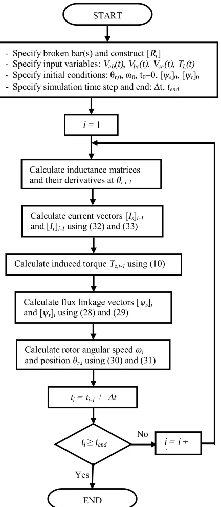
The simulation procedure proceeds as indicated in the flowchart of Figure 4. As seen, the simulation procedure starts with the initialization stage. Then, it enters the simulation steps loop, where various parameters and variables of the SCIM are calculated at every step using given equations. The loop repeats until the end of simulation time. The stated simulation method is similar to the numerical solution of the state equations and can be performed using general purpose software codes such as MATLAB.
5. EXPERIMENTAL TEST RIG
The proposed test rig consists of an 11-kW, 380-V, 50-Hz, 4-poles, Δ-connected industrial SCIM mechanically coupled to a DC generator, while a variable resistor bank is connected to the terminals of the generator. The load of the generator, and consequently the SCIM is adjusted by varying the resistance of the resistor bank. A PC equipped with a data acquisition (DAQ) card type PCI-1710HG is used for sampling the required electrical data at certain adjustable frequency [31]. Additional rotor with broken bars are provided to do experiments under the rotor broken bar conditions. Required number of adjacent bars was broken by drilling holes in them. Figure 5 shows a photograph of the test rig.
6. COMPARISON OF SIMULATION AND
EXPERIMENTAL RESULTS
To validate the simulation results of the proposed SWFM, they are compared with the corresponding experimental results. In addition, simulation results from SWFM are compared with those from WFM to verify magnetic saturation impacts. Figure 6 shows the no-load phase current of the healthy SCIM. As seen, the current is rather sinusoidal with half-nominal stator voltage, but it is disturbed with nominal stator voltage. This is due to some degree of saturation occurring under nominal voltage.
To verify this, magnetization curve of the motor has been determined by experiment as well as simulation and is shown in Figure 7. As seen, the nominal voltage of the motor is above knee of the magnetization curve.
In both Figures 6 and 7, simulation and experimental results agree well and this implies the high accuracy of the developed SWFM.
Figure 4.The simulation procedure flowchart
Figure 5.Photograph of the test rig
Figure 6.No-load phase current of healthy SCIM with nominal (__) and half-nominal (---) stator voltages: a) simulation using
the SWFM, b) experimental.
Figure 7. Stator line voltage versus its no-load current (magnetization curve) obtained by experiment and simulation using the SWFM for the healthy SCIM and SCIM with two broken bars
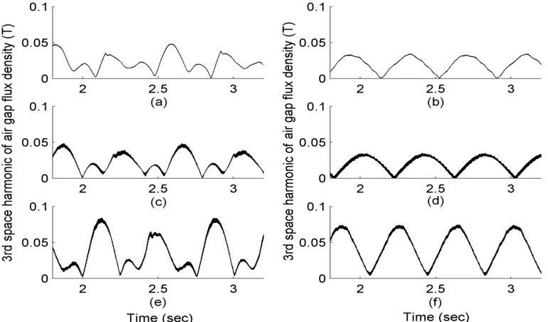
These frequency components (sidebands) are the main signatures of the broken rotor bars fault in the stator currents, which are generally used as indexes for the fault diagnosis. Normalized frequency spectra of the stator line current are shown in Figure 8 for the healthy SCIM and the SCIM with one and two broken bars under half rated load. Comparison can be made between the results obtained through simulation using the WFM and the SWFM as well as the results obtained from experiments. As seen, the sidebands are clear in the spectra and their amplitudes are amplified due to the fault. Also, the amplitudes in the SWFM results are much closer to those in the experimental results. In the SWFM and the experimental results, non-uniform effect of the magnetic saturation is the cause for the presence of the sidebands in the healthy SCIM and for the increase of their amplitudes in the faulty SCIM. This has been also reported in [4]. Therefore, the proposed SWFM provides more precise results and it is more reasonable to analyze the SCIM with broken rotor bars than the WFM. The broken rotor bar fault intensifies the space harmonics of the air gap flux density. Figure 9 shows the variation of the amplitude of the 3rd space harmonic of the air gap flux density obtained by the SWFM as well as the WFM. START
- Specify broken bar(s) and construct [Rr]
- Specify input variables: Vab(t), Vbc(t), Vca(t), TL(t)
- Specify initial conditions: θr,0, w0, t0=0, [ψs]0, [ψr]0 - Specify simulation time step and end: Δt, tend
i = 1
Calculate inductance matrices and their derivatives atθr,i-1
Calculate current vectors [Is]i-1
and [Ir]i-1 using (32) and (33)
Calculate induced torque Te,i-1 using (10)
Calculate flux linkage vectors [ψs]i
and [ψr]i using (28) and (29)
Calculate rotor angular speed ωi
and position θr,i using (30) and (31)
ti = ti-1 + ∆t
ti≥tend
END
i = i +
1
No
(i) (h)
(g)
Frequency (Hz)
Figure 8. Normalized frequency spectra of the stator line current obtained through simulation using the SWFM (a, b, c), the WFM (d, e, f) and the experiments (g, h, i) for the healthy SCIM (a, d, g), for the SCIM with one broken rotor bar (b, e, h) and for the SCIM with two broken rotor bars (c, f, i) under half rated load.
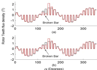
Figure 10.Estimated rotor teeth flux densities in healthy (---) and 1 broken bar (-) SCIMs obtained using: a) the SWFM and b) the WFM.
It must be noticed that the traces in the charts in this figure are not synchronized, since they are obtained from different simulation processes on the SCIM. As seen, the rotor bar breakage increases the fluctuation amplitude of the 3rd space harmonic of the air gap flux density (especially with two broken bars). Also, the clear effect of saturation on the behavior of this harmonic amplitude in the healthy and faulty SCIMs is noticeable. Due to saturation, normal tedious variation of the harmonic amplitude disturbs and its maximum value increases. The SWFM results in Figure 9 are qualitatively in agreement with the corresponding experimental result given in reference [32].
Figure 10 shows the rotor teeth flux densities determined by using rotor meshes flux linkages and by assuming the total flux passing through any rotor mesh concentrates in the relevant rotor tooth uniformly. As seen, a broken rotor bar reduces the flux of an adjacent tooth and increases that of other adjacent tooth. This is more significant in the SWFM results and leads to a higher local saturation in the latter tooth. The SWFM results are in more agreement with the similar finite elements results given in [12].
7. CONCLUSION
The flux linkages of the rotor meshes calculated in every simulation step by the winding function approach were used to estimate the air gap flux density distribution. Then, space harmonic components of the air gap flux density were determined using Fourier series analysis. The phase angle of the space fundamental harmonic was utilized to locate the air gap flux density during simulation of the faulty SCIMs. The amplitude of this fundamental harmonic is applicable to evaluate the saturation factor more reasonably. A comparison between the simulation and experimental results verified the better accuracy of the developed
saturable model, which means that more precise fault diagnosis techniques can be designed by using the proposed saturable model. The saturation impacts on various quantities of the SCIM, such as the stator line current spectrum and the air gap flux density distribution can be analyzed by comparing the results obtained from saturable and non-saturable models.
8. REFERENCES
1. Bellini, A., Filippetti, F., Franceschini, G., Tassoni, C. and Kliman, G. B., "Quantitative evaluation of induction motor broken bars by means of electrical signature analysis", Industry Applications, IEEE Transactions on, Vol. 37, No. 5, (2001), 1248-1255.
2. Romero-Troncoso, R. J., Saucedo-Gallaga, R., Cabal-Yepez, E., Garcia-Perez, A., Osornio-Rios, R. A., Alvarez-Salas, R., Miranda-Vidales, H., and Huber, N., "Fpga-based online detection of multiple combined faults in induction motors through information entropy and fuzzy inference", Industrial Electronics, IEEE Transactions on, Vol. 58, No. 11, (2011), 5263-5270.
3. Garcia-Perez, A., de Jesus Romero-Troncoso, R., Cabal-Yepez, E. and Osornio-Rios, R. A., "The application of high-resolution spectral analysis for identifying multiple combined faults in induction motors", Industrial Electronics, IEEE Transactions on, Vol. 58, No. 5, (2011), 2002-2010.
4. Bellini, A., Filippetti, F., Tassoni, C. and Capolino, G.-A., "Advances in diagnostic techniques for induction machines", Industrial Electronics, IEEE Transactions on, Vol. 55, No. 12, (2008), 4109-4126.
5. Pons-Llinares, J., Antonino-Daviu, J. A., Riera-Guasp, M., Pineda-Sanchez, M. and Climente-Alarcon, V., "Induction motor diagnosis based on a transient current analytic wavelet transform via frequency b-splines", Industrial Electronics, IEEE
Transactions on, Vol. 58, No. 5, (2011), 1530-1544.
6. Bouzida, A., Touhami, O., Ibtiouen, R., Belouchrani, A., Fadel, M., and Rezzoug, A., "Fault diagnosis in industrial induction machines through discrete wavelet transform", Industrial Electronics, IEEE Transactions on, Vol. 58, No. 9, (2011), 4385-4395.
7. Pineda-Sanchez, M., Riera-Guasp, M., Antonino-Daviu, J. A., Roger-Folch, J., Perez-Cruz, J., and Puche-Panadero, R., "Diagnosis of induction motor faults in the fractional fourier domain", Instrumentation and Measurement, IEEE
Transactions on, Vol. 59, No. 8, (2010), 2065-2075.
8. Gritli, Y., Stefani, A., Rossi, C., Filippetti, F. and Chatti, A., "Experimental validation of doubly fed induction machine electrical faults diagnosis under time-varying conditions",
Electric Power Systems Research, Vol. 81, No. 3, (2011),
751-766.
9. Faiz, J. and Ebrahimi, B.-M., "A new pattern for detecting broken rotor bars in induction motors during start-up", Magnetics, IEEE Transactions on, Vol. 44, No. 12, (2008), 4673-4683.
10. Drif, M. h. and Cardoso, A. J. M., "The use of the instantaneous-reactive-power signature analysis for rotor-cage-fault diagnostics in three-phase induction motors", Industrial Electronics, IEEE
Transactions on, Vol. 56, No. 11, (2009), 4606-4614.
12. Sprooten, J. and Maun, J.-C., "Influence of saturation level on the effect of broken bars in induction motors using fundamental electromagnetic laws and finite element simulations", Energy Conversion, IEEE Transactions on, Vol. 24, No. 3, (2009), 557-564.
13. Faiz, J., Ghorbanian, V. and Ebrahimi, B. M., "Locating broken bars in line-start and inverter-fed induction motors using modified winding function method", Electromagnetics, Vol. 32, No. 3, (2012), 173-192.
14. Moreira, J. C. and Lipo, T. A., "Modeling of saturated ac machines including air gap flux harmonic components",
Industry Applications, IEEE Transactions on, Vol. 28, No. 2,
(1992), 343-349.
15. Levi, E., "A unified approach to main flux saturation modelling in dq axis models of induction machines", Energy Conversion,
IEEE Transactions on, Vol. 10, No. 3, (1995), 455-461.
16. Bispo, D., Martins, L., de Resende, J. T. and de Andrade, D. A., "A new strategy for induction machine modeling taking into account the magnetic saturation", Industry Applications, IEEE
Transactions on, Vol. 37, No. 6, (2001), 1710-1719.
17. Tu, X., Dessaint, L.-A., Champagne, R. and Al-Haddad, K., "Transient modeling of squirrel-cage induction machine considering air-gap flux saturation harmonics", Industrial Electronics, IEEE Transactions on, Vol. 55, No. 7, (2008), 2798-2809.
18. Sizov, G. Y., Sayed-Ahmed, A., Yeh, C.-C. and Demerdash, N. A., "Analysis and diagnostics of adjacent and nonadjacent broken-rotor-bar faults in squirrel-cage induction machines", Industrial Electronics, IEEE Transactions on, Vol. 56, No. 11, (2009), 4627-4641.
19. Tuovinen, T., Hinkkanen, M. and Luomi, J., "Modeling of saturation due to main and leakage flux interaction in induction machines", Industry Applications, IEEE Transactions on, Vol. 46, No. 3, (2010), 937-945.
20. Bossio, G., De Angelo, C., Solsona, J., García, G. and Valla, M. I., "A 2-d model of the induction machine: An extension of the modified winding function approach", Energy Conversion,
IEEE Transactions on, Vol. 19, No. 1, (2004), 144-150.
21. Joksimovic, G. M., Durovic, M. D., Penman, J. and Arthur, N., "Dynamic simulation of dynamic eccentricity in induction machines-finding function approach", Energy Conversion,
IEEE Transactions on, Vol. 15, No. 2, (2000), 143-148.
22. Faiz, J. and Tabatabaei, I., "Extension of winding function theory for nonuniform air gap in electric machinery", Magnetics,
IEEE Transactions on, Vol. 38, No. 6, (2002), 3654-3657.
23. Faiz, J. and Ojaghi, M., "Unified winding function approach for dynamic simulation of different kinds of eccentricity faults in cage induction machines", IET Electric Power Applications, Vol. 3, No. 5, (2009), 461-470.
24. Luo, X., El-Antably, A. and Lipo, T. A., "Multiple coupled circuit modeling of synchronous reluctance machines", in Industry Applications Society Annual Meeting, Conference Record of the IEEE, , (1994), 281-289.
25. Bossio, G. R., De Angelo, C. H., García, G. O., Solsona, J. A. and Valla, M. I., "Effects of rotor bar and end-ring faults over the signals of a position estimation strategy for induction motors", Industry Applications, IEEE Transactions on, Vol. 41, No. 4, (2005), 1005-1012.
26. Ying, X., "Performance evaluation and thermal fields analysis of induction motor with broken rotor bars located at different relative positions", Magnetics, IEEE Transactions on, Vol. 46, No. 5, (2010), 1243-1250.
27. Faiz, J., Ebrahimi, B. M. and Toliyat, H. A., "Effect of magnetic saturation on static and mixed eccentricity fault diagnosis in induction motor", Magnetics, IEEE Transactions on, Vol. 45, No. 8, (2009), 3137-3144.
28. Nandi, S., "A detailed model of induction machines with saturation extendable for fault analysis", Industry Applications,
IEEE Transactions on, Vol. 40, No. 5, (2004), 1302-1309.
29. Ojaghi, M. and Faiz, J., "Extension to multiple coupled circuit modeling of induction machines to include variable degrees of saturation effects", Magnetics, IEEE Transactions on, Vol. 44, No. 11, (2008), 4053-4056.
30. Toliyat, H. A. and Lipo, T. A., "Transient analysis of cage induction machines under stator, rotor bar and end ring faults",
Energy Conversion, IEEE Transactions on, Vol. 10, No. 2,
(1995), 241-247.
31. Manual, D. D. U., For PCI-1710, L/HG/HGL”, ADVANTECH automation (2013).
32. Weili, L., Ying, X., Jiafeng, S. and Yingli, L., "Finite-element analysis of field distribution and characteristic performance of squirrel-cage induction motor with broken bars", Magnetics,
IEEE Transactions on, Vol. 43, No. 4, (2007), 1537-1540.
APPENDICES
Analytic equation for the stator self/mutual inductances is obtained as follows:
)] , , ( ) , , ( [ )] , ( ) ( )[ ( 1 1 sat f i sat f i m
i x ti y ti s f sat o xy K f K f K f n n rl L j j j j j j j m -´ -= + = å (A1)
where x and y represent the stator phases, m is the number of the stator slots, φi the angle of center of the
stator slot i, φti the angle of center of the stator tooth
after its slot i and functions f( ) and fs( ) are:
÷ ÷ ø ö ç ç è æ -¢ = = -ò )) ( 2 cos( 1 )) ( 2 cos( cos 1 2 1 ) , , ( ) , , ( 1 2 f f sat f s sat f p p g p K g d K f j j r r j j r j j j j j (A2) )] , , ( ) , , ( [ ) ( 2 ) ( 1 ) , ( 1 1 2 sat f i sat f i m
i y ti
sat f s K f K f n g K f j j j j j p r j -´ -¢ = + = å (A3)
The stator inductances are constants, thus their derivatives versus the rotor position are zero. Analytic equation for the rotor self/mutual inductances is obtained as follows:
)] , , ( ) , , ( [ )] , ( [ 1 0 sat f u sat f u sat f r uv K f K f K f c rl L a a a a a m -= + (A4)
where u and v represent the rotor meshes 1 to R, αf is φf
in the rotor frame of reference (αf = φf - θr), αu is the
angle of center of bar number u in the rotor frame, c is equal to 1 for u = v and equal to 0 otherwise, and function fr is:
)] , , ( ) , , ( [ 2 ) ( 1 ) , ( 1 2 sat f v sat f v sat f r K f K f g K f a a a a p r a -¢
= + (A5)
As αfdepends on the rotor position (θr), (A4) and (A5)
equation for the derivatives of the rotor inductances is obtained as follows:
)] , , ( ) , , ( [ ) , ( ] ) , , ( ) , , ( [ )] , ( [ 1 1 sat f u sat f u f sat f r o f sat f u f sat f u sat f r o uv K f K f K f l r K f K f K f c l r L a a a a a a m a a a a a a a m q -¶ ¶ + ¶ ¶ -¶ ¶ -= ¶ ¶ + + (A6) where: ] ) , , ( ) , , ( [ 2 ) ( 1 ) ,
( 2 1
f sat f y f sat f y f sat f
r K g f K f K
f a a a a a a p r a a ¶ ¶ -¶ ¶ -¢ = 
¶ + (A7)
v v u u i f i s f sat f i p g K f a a a a a a a r a a a , , , ; ))] ( 2 cos( 1 [ 1 ) , , ( 1 1 + + = -¢ -= ¶ ¶ (A8)
The mutual inductances between the rotor meshes and the stator phases are obtained as follows:
)] , , ( ) , , ( [ )] , ( ) ( [ 1 1 1 2 1 sat f i sat f i k k
i y ti s f sat o x u K f K f K f n l r L j j j j j j m -+ = -´ -=
å
(A9)where u and x represent the rotor meshes and the stator phases respectively, φk1-1and φk2+1are the angles of the
two bars of mesh u in the stator reference, k1 to k2 are
the stator slots between φk1-1 and φk2+1(e.g. φk1 is the
angle of the stator slot k1). Now φk1-1and φk2+1depend
on θr such that their derivatives versus θr are equal to 1,
while other parameters in (A9) are independent of θr.
Using these facts, and some differentiation leads to:
÷ ÷ ÷ ÷ ÷ ø ö ç ç ç ç ç è æ -¢ -+ -¢ -= ¶ ¶ + -))] ( 2 cos( 1 [ )] , ( ) ( [ ))] ( 2 cos( 1 [ )] , ( ) ( [ 1 2 2 1 1 1 1 f k sat f s k t x f k sat f s k t x o x u p g K f n p g K f n rl L j j r j j j j r j j m q (A10)
Exact Modeling and Simulation of Saturated Induction Motors with Broken Rotor
Bars Fault using Winding Function Approach
M. Ojaghia, M. Sabouria, J. Faizb, V. Ghorbanianb
a Department of Electrical Engineering, Faculty of Engineering, University of Zanjan, Zanjan, Iran
b Center of Excellence on Applied Electromagnetic System, School of Electrical and Computer Engineering, University of Tehran, Tehran, Iran
P A P E R I N F O
Paper history: Received 17 August 2013
Received in revised form 22 September 2013 Accepted 26 September 2013
Keywords:
Induction motors Broken bar fault Magnetic saturation Modeling Computer simulation هﺪﯿﮑﭼ
لﺪﻣويزﺎﺳﻪﯿﺒﺷشورﮏﯾﭻﯿﭘﻢﯿﺳﻊﺑﺎﺗشور
ﺲﻔﻗﯽﯾﺎﻘﻟايﺎﻫرﻮﺗﻮﻣدﺮﮑﻠﻤﻋﻞﯿﻠﺤﺗياﺮﺑهدﺎﺳًﺎﺘﺒﺴﻧوﻖﯿﻗديزﺎﺳ
ﯽﻣﻪﺋارابﻮﯿﻌﻣﯽﺑﺎﺠﻨﺳ
ﺪﻨﮐ
.
ﻪﻈﺤﻟﯽﯾﺎﺳﺎﻨﺷياﺮﺑشورﻦﯾا
ﺖﺳالﺎﻤﻋاﻞﺑﺎﻗﺎﻄﺧيا
.
ﭻﯿﭘﻢﯿﺳﻊﺑﺎﺗشور،ﻪﻟﺎﻘﻣﻦﯾارد
ﺎﺑ
ردلﺎﻤﻋا
ﺑﺎﺑﯽﺴﯿﻃﺎﻨﻐﻣعﺎﺒﺷاﺮﯿﻐﺘﻣتﺎﺟ
ﻪ
ﺐﯾﺮﺿﻦﯿﻤﺨﺗياﺮﺑﺪﯾﺪﺟﯽﺷورﺰﯿﻧوﺐﺳﺎﻨﻣﯽﯾاﻮﻫﻪﻠﺻﺎﻓﻊﺑﺎﺗﮏﯾندﺮﺑرﺎﮐ
ﻪﯾوازﺖﯿﻌﻗﻮﻣوزﺎﯿﻧدرﻮﻣعﺎﺒﺷا
ﺖﺳاهﺪﺷﻪﺋاراﯽﯾاﻮﻫﻪﻠﺻﺎﻓرﺎﺷﯽﻟﺎﮕﭼيا
.
ﻪﺠﯿﺘﻧرد
،
ﻢﯿﺳﻊﺑﺎﺗلﺪﻣ
عﺎﺒﺷاﭻﯿﭘ
ياﺮﺑﺮﯾﺬﭘ
ﻪﻠﯿﻣﺐﯿﻋ ياراد ﯽﺑﺎﺠﻨﺳﺲﻔﻗﯽﯾﺎﻘﻟا رﻮﺗﻮﻣﻞﯿﻠﺤﺗ
يورعﺎﺒﺷاﺮﺛا ﯽﯾﺎﺳﺎﻨﺷ ياﺮﺑ ﻦﯿﻨﭽﻤﻫورﻮﺗورهﺪﺷﻪﺘﺴﮑﺷيﺎﻫ
ﺺﺧﺎﺷ
ﺑﻪﻃﻮﺑﺮﻣﺐﯿﻋيﺎﻫ
ﻪ
ﺖﺳاﻪﺘﻓررﺎﮐ
.
ﯽﻣنﺎﺸﻧﺮﻇﺎﻨﺘﻣﯽﺸﯾﺎﻣزآﺞﯾﺎﺘﻧﺎﺑيزﺎﺳﻪﯿﺒﺷﺞﯾﺎﺘﻧﻪﺴﯾﺎﻘﻣ
ﻊﺑﺎﺗلﺪﻣﻪﮐﺪﻫد
ﻢﯿﺳ
عﺎﺒﺷاﭻﯿﭘ
ﺖﺳايدﺎﯾز ﺖﻗدياراد ﺮﯾﺬﭘ
.
عﺎﺒﺷالﺪﻣﻦﯾا زاهدﺎﻔﺘﺳاﺎﺑ ﻪﮐﺖﺳﺎﻨﻌﻣناﺪﺑﻦﯾا
ﺮﯾﺬﭘ ﯽﻣ ناﻮﺗ شور يﺎﻫ
ﻖﯿﻗدﺐﯿﻋﺺﯿﺨﺸﺗ