Order Number: 301170-001
Enhanced Intel
®
SpeedStep
®
Technology for the Intel
®
Pentium
®
M
Processor
White Paper
INFORMATION IN THIS DOCUMENT IS PROVIDED IN CONNECTION WITH INTEL® PRODUCTS. NO LICENSE, EXPRESS OR IMPLIED, BY ESTOPPEL OR OTHERWISE, TO ANY INTELLECTUAL PROPERTY RIGHTS IS GRANTED BY THIS DOCUMENT. EXCEPT AS PROVIDED IN INTEL'S TERMS AND CONDITIONS OF SALE FOR SUCH PRODUCTS, INTEL ASSUMES NO LIABILITY WHATSOEVER, AND INTEL DISCLAIMS ANY EXPRESS OR IMPLIED WARRANTY, RELATING TO SALE AND/OR USE OF INTEL PRODUCTS INCLUDING LIABILITY OR WARRANTIES RELATING TO FITNESS FOR A PARTICULAR PURPOSE, MERCHANTABILITY, OR INFRINGEMENT OF ANY PATENT, COPYRIGHT OR OTHER INTELLECTUAL PROPERTY RIGHT. Intel products are not intended for use in medical, life saving, life sustaining applications.
Intel may make changes to specifications and product descriptions at any time, without notice.
Designers must not rely on the absence or characteristics of any features or instructions marked “reserved” or “undefined.” Intel reserves these for future definition and shall have no responsibility whatsoever for conflicts or incompatibilities arising from future changes to them.
This document as well as the software described in it is furnished under license and may only be used or copied in accordance with the terms of the license. The information in this manual is furnished for informational use only, is subject to change without notice, and should not be construed as a commitment by Intel Corporation. Intel Corporation assumes no responsibility or liability for any errors or inaccuracies that may appear in this document or any software that may be provided in association with this document.
Except as permitted by such license, no part of this document may be reproduced, stored in a retrieval system, or transmitted in any form or by any means without the express written consent of Intel Corporation.
Contact your local Intel sales office or your distributor to obtain the latest specifications and before placing your product order.
Copies of documents which have an ordering number and are referenced in this document, or other Intel literature may be obtained by calling 1-800-548-4725 or by visiting Intel's website at http://www.intel.com.
AnyPoint, AppChoice, BoardWatch, BunnyPeople, CablePort, Celeron, Chips, CT Media, Dialogic, DM3, EtherExpress, ETOX, FlashFile, i386, i486, i960, iCOMP, InstantIP, Intel, Intel Centrino, Intel logo, Intel386, Intel486, Intel740, IntelDX2, IntelDX4, IntelSX2, Intel Create & Share, Intel GigaBlade, Intel InBusiness, Intel Inside, Intel Inside logo, Intel NetBurst, Intel NetMerge, Intel NetStructure, Intel Play, Intel Play logo, Intel SingleDriver, Intel SpeedStep, Intel StrataFlash, Intel TeamStation, Intel Xeon, Intel XScale, IPLink, Itanium, MCS, MMX, MMX logo, Optimizer logo, OverDrive, Paragon, PC Dads, PC Parents, PDCharm, Pentium, Pentium II Xeon, Pentium III Xeon, Performance at Your Command, RemoteExpress, SmartDie,
Solutions960, Sound Mark, StorageExpress, The Computer Inside., The Journey Inside, TokenExpress, VoiceBrick, VTune, and Xircom are trademarks or registered trademarks of Intel Corporation or its subsidiaries in the United States and other countries.
*Other names and brands may be claimed as the property of others. Copyright © 2004, Intel Corporation
White Paper 3
Contents
1.0 Introduction ... 4
2.0 Processor Support ... 4
3.0 Thermal Design Power... 5
4.0 Implementation... 6
5.0 Software Considerations ... 7
6.0 ACPI Considerations... 10
7.0 Non-ACPI Implementations ... 11
8.0 Voltage Regulator Support... 12
9.0 Conclusion... 12
1.0 Introduction
Enhanced Intel® SpeedStep® Technology has revolutionized thermal and power management by giving application software greater control over the processor’s operating frequency and input voltage. Systems can easily manage power consumption dynamically. This paper describes how this flexible power
management scheme is implemented and how designers can best integrate this technology into their current or next-generation board design.
Today’s embedded systems are demanding greater performance at equivalent levels of power consumption. Legacy hardware support for backplanes, board sizes and thermal solutions have forced design teams to place greater emphasis on power and thermal budgets. Intel has extended architectural innovation for saving power by implementing new features such as Enhanced Intel SpeedStep Technology.
Enhanced Intel SpeedStep Technology allows the processor performance and power consumption levels to be modified while a system is functioning. This is accomplished via application software, which changes the bus-to-core frequency ratio and the processor core voltage (Vcc). A variety of inputs such as system power source, processor thermal state, or operating system policy are used to determine the proper operating state.
The software model behind Enhanced Intel SpeedStep Technology has ultimate control over the frequency and voltage transitions. This software model is a major step forward over previous implementations of Intel SpeedStep technology. Legacy versions of Intel SpeedStep technology required hardware support through the chipset. Enhanced Intel SpeedStep Technology has removed the chipset hardware requirement and only requires the support of the voltage regulator, processor and operating system. Centralization of the control mechanism and software interface to the processor, and reduced hardware overhead has reduced processor core unavailability time to 10 µs from the previous generation unavailability of 250 µs.
2.0 Processor Support
Enhanced Intel SpeedStep Technology is supported on current and future generations of Intel® Pentium® M Processors. The Intel Pentium M Processor at 1.6 GHz supports six frequency and voltage operating points.
Table 1.1 Supported Performance States for the Intel® Pentium® M Processor at 1.6GHz1
Frequency Voltage
1.6 GHz (HFM) 1.484 V
1.4 GHz 1.420 V
1.2 GHz 1.276 V
1.0 GHz 1.164 V
800 MHz 1.036 V
600 MHz (LFM) 0.956 V
The top and bottom modes are commonly known as high frequency mode (HFM) and low frequency mode (LFM). These frequency and voltage operating points are stored within a read-only processor model specific register (MSR). This MSR ensures BIOS will not allow transitions to invalid states above the HFM maximum or below the LFM minimum. The other four operating points are stored within BIOS code, as a drop in voltage table provided by Intel to BIOS vendors.
White Paper 5
3.0 Thermal Design Power
The Intel power specification for components is known as Thermal Design Power, or TDP. The TDP value, along with the maximum junction temperature, defines Intel’s recommended design point for thermal solution capability. For the Intel® Pentium® M Processor, which supports Enhanced Intel SpeedStep Technology, Intel will specify the TDP for both the HFM and LFM operating states. These TDP values are specified in the Intel® Pentium® M Processor Datasheet and also shown in the following table for the 1.6 GHz and 1.1 GHz parts.
Table 1.2 HFM and LFM Thermal Design Power Points for the Intel® Pentium® M Processor at 1.6 GHz1
Frequency TDP
HFM 1.6GHz 24.5 W
LFM 600MHz 6 W
Table 1.3 HFM and LFM Thermal Design Power Points for the Low Voltage Intel® Pentium® M Processor at 1.1 GHz1
Frequency TDP
HFM 1.1GHz 12 W
LFM 600MHz 6 W
Between the HFM and LFM frequency/voltage points, the dissipated power will be approximately proportional to the square of the voltage, due to Ohm’s Law.
Equation 1.1 Ohm’s Law, where P=Power, C=Capacitance, V=Voltage, and F=Frequency
Figure 1.1 Power vs. Core Voltage for the Intel® Pentium® M Processor at 1.6GHz for its six frequency/voltage operating points (not to scale). HFM and LFM power values are TDP specifications.
4.0 Implementation
All Intel Pentium M processors have support for Enhanced Intel SpeedStep Technology. This can be verified by checking the ECX feature bit 07 in the CPUID register. Enhanced Intel SpeedStep Technology is enabled by setting the IA32_MISC_ENABLE MSR, bit 16. This bit should be written by the system BIOS upon boot.
Processor frequency/voltage transitions are initiated by writing a 16-bit value to the IA32_PERF_CTL register. If a transition is already in progress, transition to a new value will take effect subsequently. Reads of the IA32_PERF_CTL register determine the last targeted operating point. The current operating point can be read from IA32_PERF_STATUS register, which is updated dynamically.
The 16-bit encoding defining valid operating points is model-specific and Intel proprietary. See your Intel representative to obtain documentation outlining the required encoding.
By centralizing the implementation of Enhanced Intel SpeedStep Technology to the processor, software can perform a frequency/voltage operating state transition by simply writing to one register
Core Voltage [V]
1.6 GHz
Power [W]
0.956 1.036 1.164 1.276 1.420 1.484
1.4 GHz 1.2
GHz 1.0
GHz 800M
Hz 600
MHz 6
White Paper 7
Table 1.4 Enhanced Intel® SpeedStep® Technology MSRs
Register Address Hex Dec
Register Name Definition / Usage
1A0 416 IA32_MISC_ENABLE Enable Miscellaneous Processor Features. Bit 16 must be set to a 1 in order to implement Enhanced Intel® SpeedStep® Technology features.
199H 409 IA32_PERF_CTL Bits 15:0 indicate the target frequency and voltage
operating point.
198H 408 IA32_PERF_STATUS Bits 15:0 indicate the current frequency and voltage
operating point.
5.0 Software Considerations
As already noted, the software model behind Enhanced Intel SpeedStep Technology performs all
management for the frequency and voltage transitions. Microsoft* Windows* XP and the Windows Server 2003 family include complete native processor performance control to support this functionality.
The native support in Windows XP and the Windows Server 2003 family consists of two components: the kernel power policy manager and the processor driver. The kernel power policy manager owns the
decision-making and the set of rules used to determine the appropriate frequency/voltage operating state. It may make decisions based on several inputs, such as end-user power policy, processor utilization, battery level, or thermal conditions and events. The processor driver is used to make actual state transitions on the kernel power policy manager’s behalf. The driver does not initiate frequency/voltage state transitions independent of the kernel power policy manager.
Figure 1.2 Software Model for Windows XP and Windows Server 2003
End-user power policy inputs are entered via the “Power Options” icon within the Control Panel. Based on the selected policy, Windows will adjust its decision-making for power states accordingly.
Table 1.5 Relationship between power policy scheme and processor dynamic throttling policy
Power Scheme AC Power DC Power
Home/Office Desk None Adaptive
Portable/Laptop Adaptive Adaptive
Presentation Adaptive Degrade
Always On None None
Minimal Power Management Adaptive Adaptive
Max Battery Adaptive Degrade
The processor dynamic throttle policy has been defined to operate in one of four states: None, Adaptive, Constant, and Degrade. “None” will ensure the processor is always at the highest performance state currently available, barring any unique thermal conditions where hardware will force a lower state. “Adaptive” matches the performance state to current demand. “Constant” will run the processor in the lowest available frequency/voltage state. Similar to the constant state, “Degrade” will always run the processor in the lowest available frequency/voltage state. Furthermore, this policy state will utilize linear stop clock throttling if the remaining battery capacity drops below a certain threshold.
Apart from Windows XP and the Windows Server 2003 family, support also exists from Intel and Microsoft for Enhanced Intel SpeedStep Technology transitions on legacy Microsoft platforms. Legacy versions of the Windows operating system do not include complete power policy manager and driver support. Thus, Intel has released an Enhanced Intel SpeedStep Technology Applet specifically to enable this functionality on the following versions of Windows:
Kernel
Driver
Processor
MSR Read MSR Write
White Paper 9 • Microsoft Windows 2000
• Microsoft Windows 98SE
• Microsoft Windows Millennium Edition (ME) • Microsoft Windows NT 4.0
This applet is available from either Intel or an Intel OEM. See your Intel representative for more information or to order the Enhanced Intel SpeedStep Technology Applet.
The Enhanced Intel SpeedStep Technology Applet provides both a power policy and a driver to enable dynamic transitions. The end user policy is again established through the Windows Control Panel, with very similar power state operation.
Figure 1.3 Software Model for the Enhanced Intel® SpeedStep® Technology Applet on Legacy Windows Platforms
Notice the software model for legacy Windows platforms must use system management mode, which creates slightly more overhead on the system. A detailed overview of system management mode (SMM) may be found in the IA-32 Intel® Architecture Software Developer’s Manual.
Support for operating systems other than Microsoft Windows is available to varying degrees in the Linux open source community. Linux operating systems with support for ACPI 2.0 may enable performance state transitions by manually writing to the appropriate file (e.g., /proc/cpufreq or /proc/acpi/processor). Linux kernel version 2.6 and newer provides full ACPI support and maps Enhanced Intel SpeedStep Technology
GUI
(Control
Panel)
Applet
(app)
(Policy)
Applet
(driver)
SMI
Handler
(Control)
Hardware
Load GUI User preferences Set State requests Periodic Get StatePeriodic Get State Set State
MSRs to the correct object table (see Table 1.7). Although support may exist for manual performance state changes through ACPI object tables, automatic performance state change based on thermal conditions, battery life, or other user parameters is limited and dependent on operating system vendor. More information may be found at Intel’s Instantly Available Technology website at
http://developer.intel.com/technology/iapc/acpi/.
6.0 ACPI Considerations
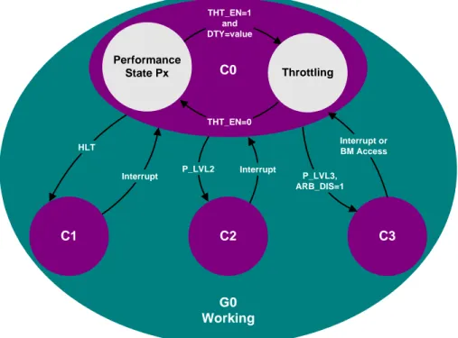
ACPI, or Advanced Configuration and Power Interface, has greatly simplified and standardized power system management. ACPI 2.0 has introduced new power states on a system, device, and processor level. This paper will introduce the processor power state levels (P-states), and map them to how Enhanced Intel SpeedStep Technology transitions are made. Other power states, such as C-states, S-states, and D-states are covered in the ACPI 2.0 specification at www.acpi.info.
Figure 1.4 Processor Performance States (P-states) Discussed Herein Are Sub-States of C0
Interrupt Interrupt
HLT
P_LVL2 THT_EN=1
and DTY=value
THT_EN=0
Performance
State Px Throttling
C1 C2 C3
P_LVL3, ARB_DIS=1
Interrupt or BM Access
G0 Working
C0
Processor P-states are defined as frequency/voltage operating states. Unlike other ACPI defined power states, such as C1, C2, etc., the processor is actually executing instructions in all P-states, since they are substates of C0. P0 is defined as the maximum performance/highest power consuming state, which is also termed HFM on an Intel Pentium M Processor. P1, P2, … Px-1, Px are defined with incrementally lower performance and power dissipation.
White Paper 11
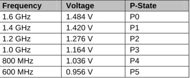
Table 1.6 P-States for the Intel® Pentium® M Processor at 1.6GHz1
Frequency Voltage P-State
1.6 GHz 1.484 V P0
1.4 GHz 1.420 V P1
1.2 GHz 1.276 V P2
1.0 GHz 1.164 V P3
800 MHz 1.036 V P4
600 MHz 0.956 V P5
ACPI 2.0 provides a standard interface for operating systems to communicate with hardware. Specific component capabilities are mapped into ACPI 2.0 tables.
Table 1.7 ACPI Object Table Definitions
ACPI 2.0 Object Table Usage
_PCT Identifies location of I/O mapped MSRs for status and control
_PSS Lists the possible processor frequency and voltage operating
states
_PPC Reflects the capabilities of the platform
It is the responsibility of the BIOS to construct and fill-in the ACPI tables. Intel provides frequency/voltage tables or a BIOS algorithm to fill the _PSS object table. After the tables have been populated, the operating system may force performance state changes by accessing the MSRs via the corresponding ACPI object tables.
7.0 Non-ACPI Implementations
ACPI is recommended for designing systems that utilize Enhanced Intel SpeedStep Technology. Deeply embedded designs not utilizing the ACPI interface may still incorporate frequency and voltage transitions by directly reading and writing to the corresponding MSRs on the processor. The chosen frequency and voltage combinations MUST match the valid combinations as presented in the processor datasheet. Any other combinations will force the processor to operate outside of specification and may cause component failure.
Centralizing implementation for real-time frequency/voltage transitions to a processor MSR has enabled deeply embedded operating systems and applications to easily change and control operating states.
8.0 Voltage Regulator Support
Processors featuring Enhanced Intel SpeedStep Technology provide multiple VID pins that are directly connected to voltage regulator. These VID pins signal the desired voltage for the processor. The pin output is mapped to a table, as listed in the corresponding processor datasheet. The corresponding voltage for the VID output is subsequently provided to the core processor plane by the voltage regulator.
Voltage regulator designs for the Intel Pentium M processor have been designed to accept core voltage inputs from 0.7 V to 1.708 V as selected by six VID pins. This wide range of voltages allows one regulator design to support all processors within the Intel Pentium M and Intel® Celeron® M families, including low voltage and ultra low voltage versions. Additionally, all processors in this family are both package and pin footprint compatible.
9.0 Conclusion
Enhanced Intel SpeedStep Technology has revolutionized thermal and power management by centralizing hardware implementation to the processor. By also giving software greater control over the transition mechanism, performance state transitions may be dynamically controlled to manage increasingly tight power and thermal budgets.
References:
• ACPI – Advanced Configuration and Power Interface
www.acpi.info
• IA-32 Intel Architecture Software Developer’s Manual Volume 3: System Programming Guide
http://developer.intel.com/design/mobile/manuals/ • Microsoft ACPI/Power Management
http://www.microsoft.com/whdc/hwdev/tech/onnow/default.mspx • Intel Pentium M Processor Datasheet
http://developer.intel.com/design/intarch/pentiumm/pentiumm.htm • Windows Native Processor Performance Control
http://www.microsoft.com/hwdev/tech/onnow/ProcPerfCtrl.asp • Instantly Available Technology – ACPI
http://developer.intel.com/technology/iapc/acpi/
• AP-485 Intel® Processor Identification and the CPUID Instruction
http://developer.intel.com/design/xeon/applnots/241618.htm Notes
1. Please refer to the Intel® Pentium® M Processor Datasheet for the latest specifications. All information included in the datasheet supersedes the material of this document.