Fire Protection
Piping Solution
Connecting
the Resources
You Need
Revised 2002
Fitting Quick Finder
This adapter is used exten-sively to connect HDPE with ductile iron pipe.
Reducers change from one pipe size to another and provide a smooth flow transition.
Elbows provide a change in direction. Fabricated ells are made using miter sections of pipe. Molded ells are made by injection molding.
The flange adapter is a solid piece of HDPE material that is sized to be used with the backup ring to make a flanged connection to anoth-er pipe flange, a pump or valve.
A backup ring is a metal ring used with bolts to make a secure connection to a pipe
Backup Rings
Class 150 and 200 . . . .20
Elbows
90° Molded & Fabricated . . .16
45° Molded & Fabricated . . .17
Flange Adapters
Class 150 and 200 . . . .19
MJ Adapters
Connectors . . . .14
Reducers
Molded & Fabricated . . . .15
Tees
Molded & Fabricated . . . .18
Branch Saddle Reducing T . .21
Tees provide a means of con-necting pipes from the side of the pipe. Standard tees pro-vide a connection of the same size as the main pipe. A reducing tee provides a con-nection smaller than the orig-inal pipe.
ISCO Industries,
LLC
HIGH DENSITY POLYETHYLENE PIPE
AND FITTINGS FOR FACTORY MUTUAL APPROVED
FIRE PROTECTION PIPING SYSTEMS
Contents
Fire Protection Piping Systems . . . .2
Material Standards . . . .3
Factory Mutual Product Properties and Dimensions . . . .4
Design Guidelines for Underground Fire Protection Piping Systems .5
Installation Procedures for HDPE Pipe . . . .6
Hydrant Installation . . . .8
Anchor Detail for HDPE Pipe . . . .9
Electrofusion Couplings . . . .10
Factory Mutual Approved ISCO Product Fittings Dimensions . . . .13-22
Sample Specifications . . . .23-26
Index . . . .29
Fire Protection Piping Systems
Fire protection systems for industrial plants usually require that all components have Factory Mutual Research Corporation (FM) approval. Large insurance companies special-izing in insuring large manufacturing plants formed Factory Mutual Research Corporation (FMRC). They found that insurance risk was reduced when the fire protection system and its components met standards set by FMRC.
Factory Mutual Research Corporation is a testing laboratory that is recognized in the USA and internationally for its work testing components for fire protection systems.
Components for fire protection systems are tested to make sure that the products meet performance, safety, and quality standards. Factory Mutual approval provides proof that components meet the requirements of a fire protection system now and will continue to meet these requirements in the event of a fire.
ISCO Industries, LLC high-density polyethylene (HDPE) fitting manufacturing facility, in Louisville, KY, has been inspected and approved by Factory Mutual Research Corporation. Our facility is inspected on an on-going basis. Our facility passes scheduled and unsched-uled inspections.
ISCO Industries manufactures high-density polyethylene (HDPE) fittings and distributes HDPE pipe manufactured to Factory Mutual standards. Both fittings and pipe are marked with the Factory Mutual diamond indicating approval.
In addition to providing pipe and fittings, ISCO Industries offers butt fusion machines for the joining of HDPE pipe and fittings. Trained and certified butt fusion technicians are available for training and to assist contractors with joining of FM HDPE during installation.
ISCO Industries manufactures high-density polyethylene (HDPE) fittings and distributes HDPE pipe manufactured to Factory Mutual standards.
Material Standards
ISCO Industries fabricates FM approved fittings from high-density polyethylene pipe that meets ASTM D 3350-02 with a cell classification of 345464C. High-density polyethylene (HDPE) pipe made to this standard is tested specifically for piping requirements.
In order to use the FM diamond, products made in our manufacturing facility must pass Factory Mutual product tests and records of testing and quality control must be main-tained. At ISCO, we take pride in the fact that we produce and test products that meet or exceed the requirements of Factory Mutual.
Manufacturing Standards
Factory Mutual Research Corporation (FMRC) has approved fittings fabricated by ISCO. FMRC has been present while fittings have been manufactured and tested.
Fittings are made to American Water Works Association requirements. Fittings for AWWA applications are tested to AWWA standards.
ISCO goes beyond the requirements of FMRC and AWWA. ISCO uses Data Loggers to mon-itor and record the results of fusion welds made in our shops. This provides constant quality monitoring and traceability of welds. Presently, no other supplier of fittings pro-vides this additional quality control step.
Piping Material Properties
●Fire protection HDPE pipe and fittings systems are approved by Factory Mutual.
●HDPE piping products offer superior toughness and ductility to other plastics.
●Pipe and fittings have exceptional resistance to Rapid Crack Propagation.
●Excellent Environmental Stress Crack Resistance (ESCR) for both pipe and fittings.
Factory Mutual Research Corporation (FMRC) has approved fittings fabricated by ISCO.
Design Guidelines for Underground Fire Protection
Piping Systems
Fluid Flow
High-density polyethylene pipe (HDPE) is smooth, non-porous, and the surface is non-wet-ting. The smooth surface provides a Roughness Coefficient, also known as the C factor, of 150 for Hazen-Williams calculations. With the non-porous nature of HDPE pipe, the C factor does not change with time. The pipe does not rust, rot, pit, or corrode.
The combination of the C factor of 150 and the fact that it does not change over time means lower operating cost. Since in most situations the pipe surface does not change, pumping costs remain low.
Fittings create pressure drop in the piping system. This pressure drop is caused by the additional turbulence caused by flow through the fitting. In many situations the pipe can be bent and the number of fittings in the system reduced.
Pressure drop through a fitting is usually expressed in terms of the length of pipe equal to the pressure drop created. The total pressure loss for the piping system is equal to the pressure drop for the length of pipe plus the pressure loss for fittings.
Table 3. Pressure Drop Through Fittings
Fitting Equiv. Length Fitting Equiv. Length
90 Degree Molded Ell 30D 90 Degree Fabricated Ell 30D
45 Degree Molded Ell 16D 45 Degree Fabricated Ell 16D
Branch Tee (Side Flow) 50D Tee Running 20D
Where "D" is the inside diameter of fitting in feet
Surge Pressure
The combination of the C factor of 150 and the fact that it does not change over time means lower operating cost.
The pressure rating for HDPE pipe decreases as temperature increases. When using HDPE pipe at elevated temperature, the pressure must be derated, as in Table 2.
High-density polyethylene pipe does not become brittle at 32 degrees F. Water if allowed, can freeze in the pipe without damaging the pipe. Upon thawing, the pipe returns to normal. In fact, HDPE pipe is a good insulator and its low conductivity reduces the risk of freezing compared to other piping materials.
Chemical Resistance
Most inorganic acids and bases do not attack HDPE pipe, especially those found in the soil or in wastewater. Hydrocarbons tend to reduce the pressure rating. As the tempera-ture and concentration of inorganic or hydrocarbons compounds increases, the more like-ly they are to affect HDPE pipe.
Cathodic protection is not needed for HDPE piping systems. In Fire Water Protection sys-tems, there is no need to protect HDPE from electrolytic attack.
Installation Procedure for FM HDPE Pipe
The high-density polyethylene pipe shall be used for underground fire protection systems only. Above ground use of HDPE pipe is not approved.
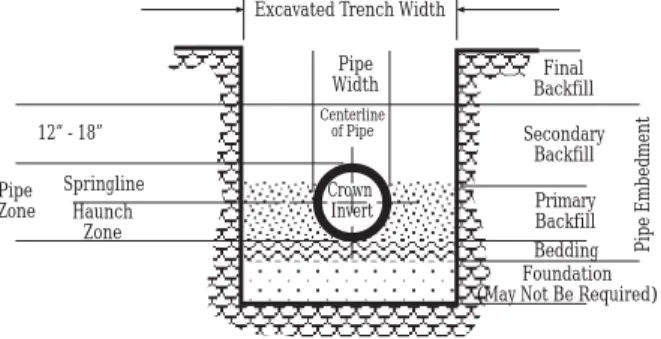
Underground HDPE piping systems should be installed using suitable trenching and backfill procedures. Determine the soil types to be trenched. When existing soils are suitable, no bedding or foundation is required. Caution! Soils vary widely. A profes-sional engineer should be consulted before making assumptions about foundation, bedding, and backfill.
The soil-pipe interaction provides excellent strength and support for underground HDPE piping systems. The reference standard for direct burial of HDPE pipe is ASTM 2774.
Figure 1. A typical trench detail for direct burial.
The flexibility of HDPE pipe reduces the need for fittings. In many situations ells of 22.5 degrees or less are not required. For most pipe sizes, a 90-degree ell can be formed in 20 to 50 pipe diameters.
Excavated Trench Width
12” - 18” Pipe Zone Springline Pipe Width Crown Invert Centerline of Pipe Final Backfill Secondary Backfill Bedding Foundation (May Not Be Required)
Primary Backfill
Pipe Embedment
Haunch Zone The chemical resistance of
HDPE pipe is excellent to acid, bases and many hydrocarbons.
Thrust Blocks
The National Fire Protection Association (NFPA) 24, Under section 10.8 Joint Restraint, Part 10.8.1.2, indicates that "Piping with fused, … or welded joints shall not require addi-tional restraining, provided that such joints can pass the hydrostatic test of 10.10.2.2 with-out shifting of piping or leakage in excess of permitted amounts."
This position by NFPA confirms the position taken by the Plastic Pipe Institute and most high-density polyethylene pipe manufacturers that thrust blocks are not needed when HDPE is properly backfilled. As with most questions, the specific application and condi-tions must be analyzed and good engineering judgment applied.
Pipe movement due to elastic deformation, thermal expansion/contraction and other forms of movement are not harmful to HDPE pipe. Pipe movement is greatly reduced by proper compaction.
The goal of proper compaction is to prevent excessive bending moments on fittings and end connections. Proper compaction of HDPE pipe is usually defined as obtaining a soil modulus of 1,000 psi or a proctor density of 85%. When proper compaction can be obtained with native soils, the system normally functions satisfactorily.
In conditions where the native soil will not provide adequate soil support for fittings, there are installation methods that will improve compactions around fittings in the sys-tem. These are listed below:
1. Use geotextile fabrics to separate poor soils from good backfill. Drawing x below shows an example of the use of geotextile fabrics.
2. Use cement stabilized with sand or soil to provide soil stabilization. 3. Use flowable fill for backfill.
An engineer with experience in soils will be needed to determine the best was to solve poor soil conditions. The information provided here is to suggest alternatives but is no substitute for engineering analysis.
Drainage Fabric
NFPA 24 does not require thrust blocks for fused pipe.
Hydrant
MJ Adapter MJ Adapter
Gate Valve
Sand: Stabilized with Concrete around 90° Ell
Valve Box
Valve Stem
HDPE Reducing Tee
HDPE Fire Main Concrete Pad to
Support Valve
Sand Stabilized with Concrete
Hydrant Installation
Where local soils will not provide the needed support for the HDPE pipe, heavy thrust blocks or dense concrete mixes can sink. When a large thrust block sinks, it creates the excessive bending moment and failure that we are trying to avoid.
In summary, where good local soil conditions exist, no thrust blocks or special bedding is required. Where local soil conditions do not provide needed soil conditions, the use of geotextile fabrics, flowable fill or stabilized soils offer another way to provide good proper support to pipe and fittings to prevent excessive bending.
Anchor Detail for HDPE Pipe
Anchors are used to limit movement of HDPE when it attaches to other types of pipe or when a connection is made to a pump or valve at the end of a line. Drawing 2 shows rebar located near the force restraint collar where the force of expansion or contraction may be greater than un-reinforced concrete can handle.
The anchor is sized to transfer the force from the HDPE pipe to the soil. The anchor is sized based on the ability of the soil to handle loading. Typical soils will handle 6 to 10 psi force depending upon the type of soil and its compaction.
Hydrostatic Testing
For safety reasons, high-density polyethylene pipelines should be tested with water. Air testing is not recommended. Pressure tests are normally conducted at 1.5 times the design service pressure. A Class 150, DR 11, pipe system is tested at 225 psi and a Class 200, DR 9, pipe system is tested at 300 psi. The test pressure is referenced to the lowest point in the system. The total time at test pressure should not exceed 3 hours.
Warning: Take appropriate safety precautions to eliminate danger to per-sonnel during testing. Risks include: sudden movement of pipe, failed
bolts and threads on flanges and valves.
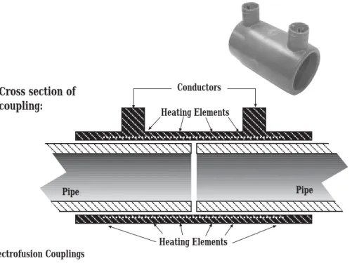
Electrofusion Couplings
Friatec Safety Fittings (electrofusion couplings) are approved by Factory Mutual(FM) for use in HDPE Fire Protection Piping Systems in Class 150 and Class 200. Friatec electrofu-sion couplings have passed the required FM testing for this approval in sizes from. Also, Friatec offers metric electrofusion couplings that have passed FM testing in Europe.
Electrofusion Couplings provide an ideal method of fusing HDPE pipe where it is difficult to get butt fusion equipment into limited space situations. Repairs and tie-in connections can be made easily with electrofusion couplings. FM approved couplings are available in sizes from 4" to 20". A drawing of a typical electrofusion coupling is shown below.
Conductors Pipe Pipe Heating Elements Heating Elements
Cross section of
coupling:
Figure 2. Electrofusion Couplings
FM approved electrofusion couplings are available in Class 200 in sizes from 4" to 20".
Factory Mutual Approved Mechanical Connections
Mechanical Connections can be made with HDPE pipe using flanges and mechanical joint adapters (MJ). Both types of connections have been approved by Factory Mutual. The MJ adapters are discussed in the next section.
Flange connections are used to make connections between HDPE pipe and pumps, valves and other types of pipe. A flange connections consist of an HDPE flange adapter fused to the end of the HDPE pipe and a metal back-up ring with bolts to make the connection. Figure 3 shows both an HDPE to steeland HDPE to HDPE flange connection.
MJ Adapters
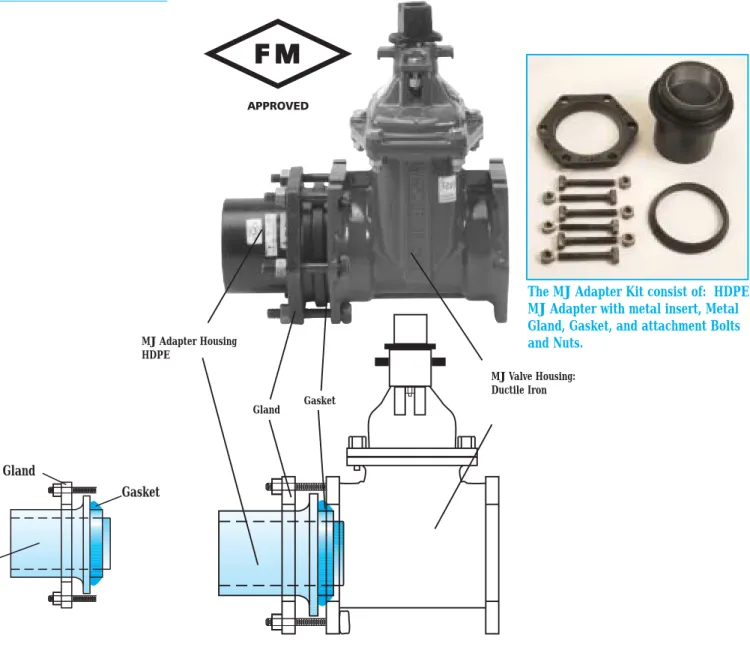
Mechanical joint (MJ) adapters are available for HDPE pipe. The MJ adapter is used to make connections between HDPE pipe and MJ valves and fire hydrants. This style of connection is used extensively with ductile iron pipe. The availability of this MJ adapter makes it much easier to use HDPE pipe with standard MJ components. The picture below shows an MJ connection using ISCO MJ Adapter Kit.
Figure 4. HDPE MJ Adapter (in Light Blue) showing interface to Ductile Iron MJ
MJ Valve Housing: Ductile Iron MJ Adapter Housing HDPE Gasket Gland
This adapter is used exten-sively to connect HDPE with ductile iron pipe/fittings.
The MJ Adapter Kit consist of: HDPE MJ Adapter with metal insert, Metal Gland, Gasket, and attachment Bolts and Nuts.
Gland
Gasket
Pressure Ratings for Molded and Fabricated Fittings
Fittings serve the purpose of creating a change of direction in a short distance. There are two principal types of fittings, molded and fabricated. Molded fittings are fully pressure rated. Picture 1 shows a molded 90 degree elbow. Note the greater thickness in the body of the ell to maintain the pressure rating.
Fabricated fittings have a reduced pressure rating because of mitered cuts create a change in the diameter at the miter. Stress is increased because of the change of direc-tion. These factors cause mitered fitting to have a reduced pressure rating if they have the wall thickness or dimensional ratio is the same as the pipe. Picture 2 shows a fabricated 90 degree ell.
The American Society of Mechanical Engineers (ASME) has established standards to design mitered fittings in steel and plastic. These standards are in ASME B31.3 para-graph number 304.2. Equations 4a and 4b are used to determine the pressure rating.
For five pieces mitered 90 degree and 45 degree ells based on a 22.5 degree miter cuts, the departing factor is 25% of the rating of the pipe. A DR 17 pipe has a pressure rating of 100 psi. Fittings made from DR 17 pipe have a pressure rating of 75 psi.
ISCO Factory Mutual mitered fittings are made from one DR thicker pipe to maintain the same pressure rating. Class 200 pipe is made using DR 9 HDPE pipe. Class 200 fittings are made using DR 7 pipe to maintain the same pressure rating. Class 150 pipe is made from DR 11 pipe. Fittings for Class 150 systems are made from DR 9 pipe.
Factory Mutual requires that class 200 pipe and fittings be tested at 800 pi for 5 minutes. This test is a good indication of the pipe and fittings ability to handle water hammer cause by the quick closing of a valve.
It is accepted practice to butt weld fittings of one DR greater thickness to HDPE pipe with one DR less. Class 200 DR 9 pipe can be butt fused to DR 7 fittings easily. Class 150 DR 11 pipe can be butt fused to DR 9 fittings easily. Ask one of our PPI Butt Fusion Welding Procedures.
Fabricated fittings are made using thicker HDPE pipe (lower DR) because the miter cut changes the pressure rating.
The MJ adapter is used to
connect HDPE pipe and
fittings to ductile iron
mechanical joint fittings,
valves and hydrants.
LO.D. D3
D2
MJ Adapter
Nominal Pipe Pressure Part # Dimensions Weight Shipping
Size OD (in) Class L(in) D2(in) D3(in) Lbs. Method
2" 2.375 200 ISMFMJ02C200FM 8.0 2.375 3.5 10 UPS 150 ISMFMJ02C150FM 9 3" 3.5 200 ISMFMJ03C200FM 8.0 3.96 5.37 11 UPS 150 ISMFMJ03C150FM 10 4" 4.5 200 ISMFMJ04C200FM 8.0 4.8 6.625 13 UPS 150 ISMFMJ04C150FM 12 6" 6.625 200 ISMFMJ06C200FM 9.0 6.9 8.625 23 UPS 150 ISMFMJ06C150FM 18 8" 8.625 200 ISMFMJ08C200FM 11.5 9.05 10.75 36 UPS 150 ISMFMJ08C150FM 35 10" 10.75 200 ISMFMJ10C200FM 11.5 11.1 13.2 48 UPS 150 ISMFMJ10C150FM 45 12" 12.75 200 ISMFMJ12C200FM 11.5 13.2 15.38 62 UPS 150 ISMFMJ12C150FM 60 14" 14.00 200 ISMFMJ14C200FM 12.5 15.3 17.5 87 UPS 150 ISMFMJ14C150FM 84 16" 16.00 200 ISMFMJ16C200FM 12.5 17.4 20 120 UPS 150 ISMFMJ16C150FM 115 18" 18.00 200 ISMFMJ18C200FM 12.5 19.5 22 132 UPS 150 ISMFMJ18C150FM 125
Reducer
L C B
Nom. Dimension (L) Dimension (B) Dimension (C) Weight Shipping
Size Part Number Class 150 / 200 Class 150 / 200 Class 150 / 200 Lbs. Method
3"X 2" ISMFCR03X02C200FM 6.50" 2.875" 2.625" 1 UPS ISMFCR03X02C150FM 1 4"X 3" ISMFCR04X03C200FM 6.375" 2.875" 2.625" 2 UPS ISMFCR04X03C150FM 1 6"X 4" ISMFCR06X04C200FM 7.50" 3.0" 2.625" 5 UPS ISMFCR06X04C150FM 5 8"X 6" ISMFCR08X06C200FM 9.380" 4.0" 4.0" 11 UPS ISMFCR08X06C150FM 10 10"X 8" ISMFCR10X08C200FM 16.0" 6.0" 6.0" 19 UPS ISMFCR10X08C150FM 17 12"X 10" ISMFCR12X10C200FM 16.0" 6.0" 6.0" 27 UPS ISMFCR12X10C150FM 25 14"X 12" ISMFCR14X12C200FM 18.0" 7.0" 7.0" 39 UPS ISMFCR14X12C150FM 28 16"X 14" ISMFCR16X14C200FM 18.0" 7.0" 7.0" 50 UPS ISMFCR16X14C150FM 42 18"X 16" ISMFCR18X16C200FM 18.0" 7.0" 7.0" 65 UPS ISMFCR18X16C150FM 55
FC W R
H
Elbows: 90° Molded and Fabricated
FC W
W
W
Fabricated 90º Elbows
Nominal Pipe Pressure Part # Dimensions Weight Shipping
Size OD (in) Class R(in) H(in) FC(in) W(in) Lbs. Method
8" 8.625 200 ISFF9008C200FM 19.4 6.0 22.4 26.7 45 UPS 150 ISFF9008C150FM 37 10" 10.75 200 ISFF9010C200FM 20.4 6.0 23.5 28.8 75 UPS 150 ISFF9010C150FM 61 12" 12.75 200 ISFF9012C200FM 26.5 8.0 30.5 36.8 125 UPS 150 ISFF9012C150FM 101 14" 14.00 200 ISFF9014C200FM 27.1 8.0 31 38 155 LTL 150 ISFF9014C200FM 126 16" 16.00 200 ISFF9016C200FM 33.1 10.0 38.1 46.1 240 LTL 150 ISFF9016C150FM 144 18" 18.00 200 ISFF9018C200FM 34.1 10.0 39.1 48.1 311 LTL 150 ISFF9018C150FM 252 Molded 90º Elbows
Nominal Pipe Pressure Part # Dimensions Weight Shipping
Size OD (in) Class H(in) FC(in) W(in) Lbs. Method
2" 2.375 200 ISMF9002C200FM 3.0 4.5 3 1 UPS 150 ISMF9002C150FM 1 3" 3.5 200 ISMF9003C200FM 3.0 5.1 3 2 UPS 150 ISMF9003C150FM 2 4" 4.5 200 ISMF9004C200FM 3.0 5.8 3 5 UPS 150 ISMF9004C150FM 4 6" 6.625 200 ISMF9006C200FM 3.0 9.0 3 12 UPS 150 ISMF9006C150FM 11
W
FC H
R
Elbows: 45° Molded and Fabricated
H FC W FC W Molded 45º Elbows
Nominal Pipe Pressure Part # Dimensions Weight Shipping
Size OD (in) Class H(in) FC(in) W(in) Lbs. Method
3" 3.5 200 ISMF4503C200FM 3.0 5.1 3 3 UPS 150 ISMF4503C150FM 3 4" 4.5 200 ISMF4504C200FM 3.0 5.8 3 3 UPS 150 ISMF4504C150FM 3 6" 6.626 200 ISMF4506C200FM 3.0 9.0 3 10 UPS 150 ISMF4506C150FM 9
“Tees ”: Molded and Fabricated
H L FC B L B FC H Molded “Tee”Nom. Dim (L) Dim (H) Dim (FC) Dim (B) Weight Shipping
Size Part Number Lbs. Method
2" ISMFTE02C200FM 10.3 3.0" 4.80" 1 UPS ISMFTE02C150FM 1 3" ISMFTE03C200FM 10.2 3.0" 5.10" 3 UPS ISMFTE03C150FM 3 4" ISMFTE04C200FM 11.2 3.0" 5.60" 5 UPS ISMFTE04C150FM 4 6" ISMFTE06C200FM 14.9 3.0" 7.40" 15 UPS ISMFTE06C150FM 14 Fabricated “Tee”
Nominal Pipe Pressure Part # Dimensions Weight Shipping
Size OD (in) Class R(in) H(in) FC(in) W(in) Lbs. Method 8" 8.625 200 ISFFTE08C200FM 48.0 19.69 24.0 19.69 73 UPS 150 ISFFTE08C150FM 59 10" 10.75 200 ISFFTE10C200FM 48.0 18.63 24.0 18.63 108 UPS 150 ISFFTE10C150FM 88 12" 12.75 200 ISFFTE12C200FM 48.0 17.63 24.0 17.63 153 UPS 150 ISFFTE12C150FM 124 14" 14.00 200 ISFFTE14C200FM 48.0 17.0 24.0 17.00 180 LTL 150 ISFFTE14C150FM 146 16" 16.00 200 ISFFTE16C200FM 48.0 16.00 24.0 16.00 230 LTL 150 ISFFTE16C150FM 186 18" 18.00 200 ISFFTE18C200FM 48.0 15.00 24.0 15.00 317 LTL 150 ISFFTE18C150FM 257 Class 150 / 200
Flange Adapter
L T D
Flange Adpater
Nominal Pipe Pressure Part # Dimensions Weight Shipping
Size OD (in) Class T(in) L(in) D(in) Lbs. Method
2" 2.375 200 ISMFFA02C200FM 0.4 6.0 4.0 0.6 UPS 150 ISMFFA02C150FM 0.4 0.4 3" 3.5 200 ISMFFA03C200FM 0.6 6.0 5.0 1.2 UPS 150 ISMFFA03C150FM 0.6 1.1 4" 4.5 200 ISMFFA04C200FM 0.8 6.0 6.6 2.1 UPS 150 ISMFFA04C150FM 0.8 2 6" 6.625 200 ISMFFA06C200FM 0.8 8.0 8.5 5.3 UPS 150 ISMFFA06C150FM 0.8 4.7 8" 8.625 200 ISMFFA08C200FM 1.6 9.0 10.6 10 UPS 150 ISMFFA08C150FM 1.6 9 10" 10.75 200 ISMFFA10C200FM 1.6 9.0 12.8 20 UPS 150 ISMFFA10C150FM 1.3 18 12" 12.75 200 ISMFFA12C200FM 2.3 10.8 15.0 25 UPS 150 ISMFFA12C150FM 1.5 24 14" 14.00 200 ISMFFA14C200FM 2.6 11.0 17.5 38 UPS 150 ISMFFA14C150FM 1.7 34.3 16" 16.00 200 ISMFFA16C200FM 3.0 12.0 20.0 48.5 UPS 150 ISMFFA16C150FM 1.9 38.1 18" 18.00 200 ISMFFA18C200FM 3.3 12.0 21.1 59 UPS 150 ISMFFA18C150FM 2.1 48
Back Up Rings (For use with the Flange Adapter)
D
T
BC
H
Backup RingNominal Pipe Pressure Part # Dimensions Weight Shipping
Size OD (in) Class OD(in) T(in) Bolts(#) H(in) BC(in) Lbs. Method
2" 2.375 200 BU02C200FM 6 0.75 4 0.75 4.75 3 UPS 150 BU02C150FM 3" 3.5 200 BU03C200FM 7.5 0.94 4 0.75 6 4 UPS 150 BU03C150FM 4" 4.5 200 BU04C200FM 9 0.94 8 0.75 7.5 5.5 UPS 150 BU04C150FM 6" 6.625 200 BU06C200FM 11 1 8 0.875 9.5 7 UPS 150 BU06C150FM 8" 8.625 200 BU08C200FM 13.5 1.12 8 0.875 11.75 11 UPS 150 BU08C150FM 10" 10.75 200 BU10C200FM 16 1.19 12 1 14.25 16 UPS 150 BU10C150FM 12" 12.75 200 BU12C200FM 19 1.5 12 1 17 25 UPS 150 BU12C150FM 1.25 22 14" 14.00 200 BU14C200FM 21 1.63 12 1.125 18.75 38 UPS 150 BU14C150FM 1.38 30 16" 16.00 200 BU16C200FM 23.5 1.88 16 1.125 21.25 54 UPS 150 BU16C150FM 1.44 40 18" 18.00 200 BU16C200FM 25 1.75 16 1.25 22.75 52 UPS 150 BU16C150FM 1.56 45
Branch Saddle Reducing “Tee”
L FC
H B
Nominal Pipe Pressure Part # Dimensions Weight Shipping
Size OD (in) Class L(in) H(in) FC(in) B(in) Lbs. Method 3"x 2" 3.5 x 2.375 200 ISFFRT03X02C200FM 16.0 6.13 6.625 5 5 UPS 3.5 x 2.375 150 ISFFRT03X02C150FM 4 4"x 2" 4.5 x 2.375 200 ISFFRT04X02C200FM 16.0 6.13 6.625 5 6 UPS 4.5 x 2.375 150 ISFFRT04X02C150FM 6 4"x 3" 4.5 x 3.5 200 ISFFRT04X03C200FM 24.0 9.5 6.625 3.75 10 UPS 4.5 x 3.5 150 ISFFRT04X03C150FM 9 6"x 2" 6.625 x 2.375 200 ISFFRT06X02C200FM 16.0 6.13 7.3 5 10 UPS 6.625 x 2.375 150 ISFFRT06X02C150FM 9 6"x 3" 6.625 x 3.5 200 ISFFRT06X03C200FM 24.0 9.5 7.3 3.75 16 UPS 6.625 x 3.5 150 ISFFRT06X03C150FM 14 6"x 4" 6.625 x 4.5 200 ISFFRT06X04C200FM 24.0 9.0 8.3 5 19 UPS 6.625 x 4.5 150 ISFFRT06X04C150FM 17 8"x 2" 8.625 x 2.375 200 ISFFRT08X02C200FM 16.0 6.13 8.3 5 16 UPS 8.625 x 2.375 150 ISFFRT08X02C150FM 14 8"x 3" 8.625 x 3.5 200 ISFFRT08X03C200FM 24.0 9.5 8.3 3.75 25 UPS 8.625 x 3.5 150 ISFFRT08X03C150FM 21 8"x 4" 8.625 x 4.5 200 ISFFRT08X04C200FM 24.0 9.0 9.8 5 28 UPS 8.625 x 4.5 150 ISFFRT08X04C150FM 24 8"x 6" 8.625 x 6.625 200 ISFFRT08X06C200FM 28.0 9.81 10.3 7 38 UPS 8.625 x 6.625 150 ISFFRT08X06C150FM 33 10"x 2" 10.75 x 2.375 200 ISFFRT10X02C200FM 16.0 6.13 9.375 5 23 UPS 10.75 x 2.375 150 ISFFRT10X02C150FM 20 10"x 3" 10.75 x 3.5 200 ISFFRT10X03C200FM 24.00 9.5 9.375 3.75 36 UPS
Nominal Pipe Pressure Part # Dimensions Weight Shipping Size OD (in) Class L(in)H(in)FC(in) B(in) Lbs. Method 12"x 10" 12.75 x 10.75 200 ISFFRT12X10C200FM 30 8.75 30.375 6 85 LTL 12.75 x 10.75 150 ISFFRT12X10C150FM 75 14"x 2" 14.00 x 2.375 200 ISFFRT14X02C200FM 16 6.13 11 5 38 UPS 14.00 x 2.375 150 ISFFRT14X02C150FM 32 14"x 3" 14.00 x 3.5 200 ISFFRT14X03C200FM 24 9.5 11 3.75 57 UPS 14.00 x 3.5 150 ISFFRT14X03C150FM 49 14"x 4" 14.00 x 4.5 200 ISFFRT14X04C200FM 24 9 12.5 5 60 UPS 14.00 x 4.5 150 ISFFRT14X04C150FM 52 14"x 6" 14.00 x 6.625 200 ISFFRT14X06C200FM 28 9.81 13 7 76 LTL 14.00 x 6.625 150 ISFFRT14X06C150FM 65 14"x 8" 14.00 x 8.625 200 ISFFRT14X08C200FM 30 9.88 13 5.5 87 LTL 14.00 x 8.625 150 ISFFRT14X08C150FM 74 14"x 10" 14.00 x 10.75 200 ISFFRT14X10C200FM 30 8.75 31 22 97 LTL 14.00 x 10.75 150 ISFFRT14X10C150FM 84 16"x 2" 16.00 x 2.375 200 ISFFRT16X02C200FM 16 6.13 12 5 49 UPS 16.00 x 2.375 150 ISFFRT16X02C150FM 41 16"x 3" 16.00 x 3.5 200 ISFFRT16X03C200FM 24 9.5 12 3.75 74 UPS 16.00 x 3.5 150 ISFFRT16X03C150FM 62 16"x 4" 16.00 x 4.5 200 ISFFRT16X04C200FM 24 9 13.5 5 77 UPS 16.00 x 4.5 150 ISFFRT16X04C150FM 65 16"x 6" 16.00 x 6.625 200 ISFFRT16X06C200FM 28 9.81 14 7 95 LTL 16.00 x 6.625 150 ISFFRT16X06C150FM 81 16"x 8" 16.00 x 8.625 200 ISFFRT16X08C200FM 30 9.88 14 5.5 107 LTL 16.00 x 8.625 150 ISFFRT16X08C150FM 91 16"x 10" 16.00 x 10.75 200 ISFFRT16X10C200FM 30 8.75 32 23 117 LTL 16.00 x 10.75 150 ISFFRT16X10C150FM 101 16"x 12" 10.75 x 8.625 200 ISFFRT16X12C200FM 32 8.6 32 23 133 LTL 10.75 x 8.625 150 ISFFRT16X12C150FM 116 18"x 2" 18.00 x 2.375 200 ISFFRT18X02C200FM 16 6.13 13 5 61 UPS 18.00 x 2.375 150 ISFFRT18X02C150FM 41 18"x 3" 18.00 x 3.5 200 ISFFRT18X03C200FM 24 9.5 13 3.75 92 UPS 18.00 x 3.5 150 ISFFRT18X03C150FM 62 18"x 4" 18.00 x 4.5 200 ISFFRT18X04C200FM 24 9 14.5 5 95 UPS 18.00 x 4.5 150 ISFFRT18X04C150FM 65 18"x 6" 18.00 x 6.625 200 ISFFRT18X06C200FM 28 9.81 15 7 117 LTL 18.00 x 6.625 150 ISFFRT18X06C150FM 81 18"x 8" 18.00 x 8.625 200 ISFFRT18X08C200FM 30 9.88 15 5.5 130 LTL 18.00 x 8.625 150 ISFFRT18X08C150FM 91 18"x 10" 18.00 x 10.75 200 ISFFRT18X10C200FM 30 8.75 33 24 140 LTL 18.00 x 10.75 150 ISFFRT18X10C150FM 101 18"x 12" 18.00 x 12.75 200 ISFFRT18X12C200FM 32 8.6 33 24 157 LTL 18.00 x 12.75 150 ISFFRT18X12C150FM 116
Sample Specifications for Factory Mutual Approved High
Density Polyethylene Pipe and Fittings
1. General Terms and Conditions
1.1 Scope.This specification covers requirements for Factory Mutual Approved PE 3408 high density polyethylene pipe and fittings for fire protection lines underground. 1.2 Engineers Approved Plans.Fire protection lines located underground shall be con-structed in accordance with plans and specifications prepared by a Professional Engineer. 1.3 Standards. All standards and specifications referenced shall be the latest edition and version thereof. This includes ASTM, ANSI, and Federal specifications and standards. 1.4 Licenses and Permits. All construction work related to underground fire protection systems shall be performed by a licensed and bonded General Contractor. Permits and licenses must be obtained prior to construction.
1.5 Inspections. An Authorized Representative of the Owner shall inspect all work. The Authorized Representative shall have the authority to halt construction if these specifica-tions, construction standards, or OSHA or Owners safety policies are not being followed. Construction shall be halted until the portion of the specification or standard is corrected. Written notice of the violation is required. A copy of the written notice shall be filed with the Contractor’s license application for future review. If the deficiencies are not correct-ed, the contractor’s surety shall be required to complete the work.
1.6 Warranty and Acceptance. Materials and workmanship shall have a one-year war-ranty to be free from defects in workmanship and materials. The warwar-ranty will be from the date of completion of construction. If work has been done to the requirements of this specification, a letter of acceptance shall be provided to the contractor upon final inspec-tion. If deficiencies are discovered during the warranty period, the Contractor shall be required to correct these deficiencies without additional charge to the Owner or his agent. The Project Engineer shall determine the need for warranty repair work to be per-formed by the Contractor. The Project Engineers determination of a deficiency will bind the Contractor to make a repair in accordance with this Contract.
ISCO Industries, LLC has carefully checked the accuracy and standards used in the preparation of these sample specifications, it does not guarantee or warranty piping installations. Sample specifications are to be used as a guide to assist engineers and owners of piping systems. Sample specifications do not cover all situations or
appli-2.3 Materials. Polyethylene pipe and fittings shall be made from resin meeting the requirements of the Plastic Pipe Institute as PE3408. The resin shall meet the require-ments of ASTM D 3350-02 with a cell classification of 345464C. The requirerequire-ments of this cell classification are:
HDPE Resin Specifications
PROPERTY SPECIFICATION UNIT TYPICAL VALUE
Material Designation PPI / ASTM PE3408
Material Classification ASTM D 1248 III C 5 P34
Cell Classification ASTM D 3350-02 345464C
Density (3) ASTM D 1505 g/cm3 0.955
Melt Index (4) ASTM D 1238 gm/ 10 min 0.11
Flexural Modulus (5) ASTM D 790 psi 135,000
Tensile Strength (4) ASTM D 638 psi 3,200
Slow Crack Growth
ESCR ASTM D 1693 hours in 100% igepal >5,000
PENT (6) ASTM F 1473 hours >100
HDB @ 73 deg F (4) ASTM D 1693 psi 1,600
UV Stabilizer (C) ASTM D 1603 %C 2.5%
2.4 Interchangeability of Pipe and Fittings. High-density polyethylene pipe and fittings can be supplied by different manufacturers as long as the materials are approved by Factory Mutual and meet the above ASTM D 3350-02 cell classification.
2.5 HDPE Fire Protection Main Pipe. The HDPE pipe shall be Factory Mutual Approved, marked according to its pressure designation as Class 150 or 200, and be marked with the Factory Mutual diamond logo. Each production run of pipe shall be tested for melt index, density, % carbon, and dimensions.
2.6 HDPE Fittings. HDPE fittings shall be molded or fabricated. Factory Mutual approval shall be marked with the Factory Mutual diamond logo.
2.7 Pipe Manufacturer’s Quality Control. The pipe manufacturer shall have an on going quality control program for incoming and outgoing materials. High-density polyeth-ylene (HDPE) resins for manufacturing of pipe shall be checked for density, melt flow rate, and contamination. The manufacturer of the HDPE resin shall certify the Cell Classification as indicated in section 2.3. These incoming resins shall be approved by plant Quality Control before being converted to pipe.
Pipe shall be checked for outside diameter, wall thickness, length, roundness, and surface finish on the inside and outside and end cut.
2.8 Fittings Manufacturer’s Quality Control. The fitting manufacturer shall have an on-going quality control program for incoming and outon-going materials. The resin shall be checked as indicated in section 2.3. Pipe for fabricated fittings shall be checked as indi-cated in 2.6. Molded fittings shall be inspected for voids and knit lines. All fabriindi-cated fit-tings shall be inspected for joint quality and alignment. All fabricated fitfit-tings welds shall be made using a DataLogger. A record of the temperature, pressure and graph of the fusion cycle shall be maintained by the fitting manufacturer.
2.9 Permanent Records. The Manufacturer of the pipe and fittings shall maintain per-manent QC and QA records. DataLogger records shall be maintained on fabricated fittings.
2.10 Compliance Testing. If requested, the pipe or fittings manufacturer can be required to retest or verify certification data. All retesting shall be at the requester’s expense, and shall be performed as required in the specifications.
3.0 Joining
3.1 Plain end pipe and fittings shall be made using butt fusion. The fusion procedures shall in accordance with the manufacturer or the PPI. The fusion equipment operator shall receive training using the recommended procedure. The Contractor shall be respon-sible to verify that the fusion equipment is in good operating condition and that the opera-tor has been trained within the past twelve months. The fusion equipment shall be equipped with a Datalogger. Records of the welds (heater temperature, fusion pressure, and a graph of the fusion cycle) shall be maintained for five (5) years. Fusion beads shall not be removed for future identification.
3.2 Heat Fusion Training. The supplier of the pipe and fittings shall provide a person certified by the pipe manufacturer and the fusion equipment manufacturer to train con-tractor fusion equipment operators and inspectors representing the Owner.
3.3 Mechanical Joining. Polyethylene pipe and fittings may be joined together using flanges or Mechanical joint adapters.
3.4 Electrofusion couplings. Polyethylene pipe and fittings may be joined using FM approved electrofusion couplings. Supplier must provide information verifying the pres-sure rating on coupling and FM approval.
4.0 Installation. Pipe and fittings shall be installed using procedures recommended by the manufacturer.
4.1 General. Pipe and fittings shall be packaged in a manner suitable for shipment by a commercial carrier. Upon receipt at job site, a receiving inspection shall be prepared. The quantity shall be verified and any shipping damage shall be reported to the supplier
4.5 Foundation & Bedding. Install pipe on grade and on a stable foundation. Unstable soil or muck shall be removed from the trench bottom. A 6" foundation or bedding of compacted Class 1 material shall be in the bottom of the trench. This bedding material shall be installed on grade. Water shall be removed from the trench before bringing the bedding material and pipe to grade and backfilling. When a trench is cut through solid rock, it shall be excavated to 6" below the pipe bottom grade, and bedded with Class 1 bedding. All slabs of rock, boulders and large rocks shall be removed. ASTM 2321 is the reference specification for installation of HDPE pipe. Bedding shall be Class 1 per this specification.
4.6 Pipe and Large Fitting Handling: A nylon fabric choker sling capable of safely han-dling the weight of the pipe or fitting, shall be used to lift, place and move pipe and fit-tings.
4.7 Backfilling. Class l or II backfill shall be used for pipe embedment backfill. This material shall be compacted to at least 90% Standard Proctor Density in 6" lifts to at least 6" above the crown of the pipe.
4.8 Final Backfilling. Final backfill shall be placed in the trench and compacted to fin-ished grade. Native soils without rots, limbs, large rocks, boulders, clumps, or frozen clods or any object that could damage the pipe can be used.
5.0 Testing
5.1 Pressure testing. Pressure testing shall be conducted in accordance with the manu-facturers recommendations. For safety reasons, hydrostatic testing only will be used.
Index
American Water Works Association . . . .3
AWWA . . . .3 Backup Rings . . . .20 Elbows . . . . Fabricated 45° . . . .17 90° . . . .16 Molded 45° . . . .17 90° . . . .16 Electrofusion Coupliings . . . .10
Factory Mutual Research Corporation . . . .2
Fittings Approved for FM . . . .2
Flange Adapter . . . .19 FM . . . .2 Gasket . . . .13-14 Gland . . . .13-14 HDPE . . . .3 Hydrostatic Testing . . . .26
Installation for FM HDPE Pipe . . . .7
Mechanical Connections approved for FM . . . .11
MJ Adapter (Mechanical Joint) . . . .13
MJ Adapter Kit . . . .13
Reducers . . . .15
Reducing Tees . . . .21
Sample Specifications for FM Approved HDPE . . . .23
Service Pressure Ratings . . . .5
Surge Pressure . . . .6
Tees Branching Reducing Tee . . . .21
Molded . . . .18
Fabricated . . . .18