Fire Alarm Control Panel
MS-9600/MS-9600E
PN: 51335:E1 ECN 08-116
IMPORTANT! The SLC Manual Document #51309 must be referenced in addition to this manual when installing or servicing the Fire Alarm Control Panel.
An automatic fire alarm system–typically made up of smoke detectors, heat detectors, manual pull stations, audible warning devices, and a fire alarm control panel with remote notification capability–can provide early warning of a developing fire. Such a system, however, does not assure protection against property damage or loss of life resulting from a fire.
The Manufacturer recommends that smoke and/or heat detectors be located throughout a protected premise follow-ing the recommendations of the current edition of the National Fire Protection Association Standard 72 (NFPA 72), manufacturer's recommendations, State and local codes, and the recommendations contained in the Guides for Proper Use of System Smoke Detectors, which are made available at no charge to all installing dealers. These
docu-ments can be found at http:/www.systemsensor.com/html/
applicat.html. A study by the Federal Emergency
Manage-ment Agency (an agency of the United States governManage-ment) indicated that smoke detectors may not go off in as many as 35% of all fires. While fire alarm
systems are designed to provide early warning against fire, they do not guarantee warning or protection against fire. A fire alarm system may not provide timely or adequate warning, or simply may not function, for a variety of reasons: Smoke detectors may not sense fire where smoke cannot reach the detectors such as in chimneys, in or behind walls, on roofs, or on the other side of closed doors. Smoke detectors also may not sense a fire on another level or floor of a building. A second-floor detector, for example, may not sense a first-floor or basement fire.
Particles of combustion or "smoke" from a developing fire may not reach the sensing chambers of smoke detectors because:
• Barriers such as closed or partially closed doors, walls, or chimneys may inhibit particle or smoke flow.
• Smoke particles may become "cold," stratify, and not reach the ceiling or upper walls where detectors are located.
• Smoke particles may be blown away from detectors by air outlets.
• Smoke particles may be drawn into air returns before reaching the detector.
The amount of "smoke" present may be insufficient to alarm smoke detectors. Smoke detectors are designed to alarm at various levels of smoke density. If such density levels are not created by a developing fire at the location of detectors, the detectors will not go into alarm.
Smoke detectors, even when working properly, have sens-ing limitations. Detectors that have photoelectronic senssens-ing chambers tend to detect smoldering fires better than flam-ing fires, which have little visible smoke. Detectors that have ionizing-type sensing chambers tend to detect fast-flaming fires better than smoldering fires. Because fires develop in different ways and are often unpredictable in their growth, neither type of detector is necessarily best and a given type of detector may not provide adequate warning of a fire. Smoke detectors cannot be expected to provide adequate warning of fires caused by arson, children playing with
age of flammable materials, etc.).
Heat detectors do not sense particles of combustion and alarm only when heat on their sensors increases at a predetermined rate or reaches a predetermined level. Rate-of-rise heat detectors may be subject to reduced sensitivity over time. For this reason, the rate-of-rise feature of each detector should be tested at least once per year by a qualified fire protection specialist. Heat detectors are designed to protect property, not life.
IMPORTANT! Smoke detectors must be installed in the same room as the control panel and in rooms used by the system for the connection of alarm transmission
wiring, communications, signaling, and/or power. If
detectors are not so located, a developing fire may damage the alarm system, crippling its ability to report a fire.
Audible warning devices such as bells may not alert people if these devices are located on the other side of closed or partly open doors or are located on another floor of a building. Any warning device may fail to alert people with a disability or those who have recently con-sumed drugs, alcohol or medication. Please note that: • Strobes can, under certain circumstances, cause
seizures in people with conditions such as epilepsy. • Studies have shown that certain people, even when
they hear a fire alarm signal, do not respond or com-prehend the meaning of the signal. It is the property owner's responsibility to conduct fire drills and other training exercise to make people aware of fire alarm signals and instruct them on the proper reaction to alarm signals.
• In rare instances, the sounding of a warning device can cause temporary or permanent hearing loss. A fire alarm system will not operate without any electrical power. If AC power fails, the system will operate from standby batteries only for a specified time and only if the batteries have been properly maintained and replaced regularly.
Equipment used in the system may not be technically compatible with the control. It is essential to use only equipment listed for service with your control panel. Telephone lines needed to transmit alarm signals from a premise to a central monitoring station may be out of service or temporarily disabled. For added protection against telephone line failure, backup radio transmis-sion systems are recommended.
The most common cause of fire alarm malfunction is inadequate maintenance. To keep the entire fire alarm system in excellent working order, ongoing maintenance is required per the manufacturer's recommendations, and UL and NFPA standards. At a minimum, the require-ments of NFPA 72 shall be followed. Environrequire-ments with large amounts of dust, dirt or high air velocity require more frequent maintenance. A maintenance agreement should be arranged through the local manufacturer's representative. Maintenance should be scheduled monthly or as required by National and/or local fire codes and should be performed by authorized professional fire
While a fire alarm system may lower insurance
rates, it is not a substitute for fire insurance!
WARNING - Several different sources of power can be
connected to the fire alarm control panel. Disconnect all
sources of power before servicing. Control unit and asso-ciated equipment may be damaged by removing and/or inserting cards, modules, or interconnecting cables while the unit is energized. Do not attempt to install, service, or operate this unit until this manual is read and understood. CAUTION - System Reacceptance Test after Software
Changes. To ensure proper system operation, this product
must be tested in accordance with NFPA 72 after any programming operation or change in site-specific software. Reacceptance testing is required after any change,
addition or deletion of system components, or after any modification, repair or adjustment to system hardware or wiring.
All components, circuits, system operations, or software functions known to be affected by a change must be 100% tested. In addition, to ensure that other operations are not inadvertently affected, at least 10% of initiating devices that are not directly affected by the change, up to a maximum of 50 devices, must also be tested and proper system operation verified.
This system meets NFPA requirements for indoor dry operation at 0-49° C/32-120° F and at a relative humidity of
93 ±2% RH (non-condensing) at 32 ±2°C/90 ±3° F.
However, the useful life of the system's standby batteries and the electronic components may be adversely affected by extreme temperature ranges and humidity. Therefore, it is recommended that this system and all peripherals be installed in an environment with a nominal room tempera-ture of 15-27° C/60-80° F.
Verify that wire sizes are adequate for all initiating and indicating device loops. Refer to manual Specifications section for maximum allowable I.R. drop from the specified device voltage.
Like all solid state electronic devices, this system may operate erratically or can be damaged when subjected to lightning-induced transients. Although no system is completely immune from lightning transients and
interferences, proper grounding will reduce susceptibility.
Overhead or outside aerial wiring is not recommended, due to an increased susceptibility to nearby lightning strikes.
Consult with the Technical Services Department if any problems are anticipated or encountered.
Disconnect AC power and batteries prior to removing or inserting circuit boards. Failure to do so can damage circuits.
Remove all electronic assemblies prior to any drilling, filing, reaming, or punching of the enclosure. When possible, make all cable entries from the sides or rear. Before making modifications, verify that they will not interfere with battery, transformer, and printed circuit board location.
Do not tighten screw terminals more than 9 in-lbs. Over-tightening may damage threads, resulting in reduced terminal contact pressure and difficulty with screw terminal removal.
This system contains static-sensitive components. Always ground yourself with a proper wrist strap before handling any circuits so that static charges are removed from the body. Use static-suppressive packaging to protect electronic assemblies removed from the unit. Follow the instructions in the installation, operating, and programming manuals. These instructions must be followed to avoid damage to the control panel and associated equipment. FACP operation and reliability depend upon proper installation by authorized personnel.
Adherence to the following will aid in problem-free
installation with long-term reliability:
WARNING: This equipment generates, uses, and can radiate radio frequency energy and if not installed and used in accordance with the instruction manual, may cause interference to radio communications. It has been tested and found to comply with the limits for class A computing device pursuant to Subpart B of Part 15 of FCC Rules, which is designed to provide reasonable protection against such interference when operated in a commercial environment. Operation of this equipment in a residential area is likely to cause interference, in which case the user will be required to correct the
Canadian Requirements
This digital apparatus does not exceed the Class A limits for radiation noise emissions from digital apparatus set out in the Radio Interference Regulations of the Canadian Department of Communications. Le present appareil numerique n'emet pas de bruits radioelectriques depassant les limites applicables aux appareils numeriques de la classe A prescrites dans le Reglement sur le brouillage radioelectrique edicte par le ministere des Communications du Canada.
FCC Warning
SECTION 1: Product Description ... 12
1.1: Inventory ... 12
1.2: Features and Options ... 12
1.3: Specifications ... 14
1.3.1: Current Availability... 15
1.4: Controls and Indicators ... 16
1.5: Circuits ... 17
1.6: Components... 17
1.6.1: Intelligent Addressable Detectors: Newer Series... 18
1.6.2: Intelligent Addressable Modules: Newer Series ... 19
1.6.3: 300 Series Intelligent Addressable Devices... 20
1.6.4: Addressable Device Accessories... 20
1.7: Optional Modules ... 20
1.8: Accessories... 21
1.8.1: PK-CD Programming Utility ... 21
1.8.2: Dress Panel... 21
1.8.3: Battery Box ... 21
1.8.4: Battery Charger ... 22
1.8.4.1 CHG-75 Battery Charger ...22
1.8.4.2 CHG-120F Battery Charger ... 22
1.8.5: Annunciators ... 22
1.9: Getting Started... 23
SECTION 2: Installation ... 24
2.1: Mounting ... 24
2.2: Power... 27
2.2.1: AC Power and Earth Ground Connection... 27
2.2.2: Battery Power... 27
2.2.3: DC Power Output Connection ... 27
2.3: Relays ... 28
2.4: Notification Appliance Circuits ... 28
2.4.1: Configuring NACs ... 29
2.4.2: Style Y (Class B) NAC Wiring ... 29
2.4.3: Style Z (Class A) NAC Wiring ...30
2.5: UL Power-limited Wiring Requirements ... 31
2.6: Optional Modules and Devices ... 32
2.6.1: DACT-UD Installation ... 33
2.6.2: 4XTMF Transmitter Module Installation...36
2.6.3: Auxiliary Trouble Input (J16 & J17)... 37
2.6.4: SLC-2 Expander Module ... 38
2.6.5: Printer/PC... 39
2.6.6: Digital Communicator and Annunciators ... 40
2.6.6.1 UDACT-F Digital Alarm Communicator/Transmitter ... 40
2.6.6.2 ACM-8RF Relay Control Module ...40
2.6.6.3 BRKT-9600 Universal Bracket Installation ... 40
2.6.6.4 ACM and AFM Series Annunciators ... 42
Table of Contents
Table of Contents
3.6.1: Autoprogram ...48
3.6.2: Point Program...49
3.6.2.1 Detector Programming ...49
3.6.2.1.1 Add Detector ...49
3.6.2.1.2 Delete Detector ...50
3.6.2.1.3 Edit Detector ...50
3.6.2.2 Module Programming ...59
3.6.2.2.1 Add Module ...59
3.6.2.2.2 Delete Module ...60
3.6.2.2.3 Edit Module Screen for Monitor Module ...61
3.6.2.2.4 Edit Module Screen for Control Modules ...69
3.6.3: Zone Setup...76
3.6.3.1 Enable ...76
3.6.3.2 Disable ...77
3.6.3.3 Zone 97, 98 and 99 ...77
3.6.3.4 Zones Installed ...78
3.6.3.5 Zones Enabled ...78
3.6.3.6 Zones Disabled ...78
3.6.3.7 Zone Type ...79
3.6.4: Loop Setup ...80
3.6.4.1 Style ...80
3.6.4.2 Loop Protocol ...80
3.6.5: System Setup ...81
3.6.5.1 Trouble Reminder ...82
3.6.5.2 Banner ...82
3.6.5.3 Time-Date ...83
3.6.5.3.1 Time ...83
3.6.5.3.2 Date ...84
3.6.5.3.3 Clock Format ...84
3.6.5.3.4 Daylight Savings Time ...84
3.6.5.4 Timers ...85
3.6.5.4.1 PAS (Positive Alarm Sequence) Delay ...85
3.6.5.4.2 Pre-signal Delay ...86
3.6.5.4.3 Waterflow Delay ...86
3.6.5.4.4 AC Loss Delay ...87
3.6.5.5 NAC (Notification Appliance Circuit) ...87
3.6.5.5.1 Enabled ...88
3.6.5.5.2 Type ...89
3.6.5.5.3 Silenceable ...89
3.6.5.5.4 Auto Silence ...90
3.6.5.5.5 Coding ...90
3.6.5.5.6 Zone ...92
3.6.5.5.7 Silence Inhibited ...92
3.6.5.5.8 Synced Type ...92
3.6.5.6 Relays ...93
3.6.5.7 Canadian Option ...94
3.6.5.8 Waterflow Silenceable ...94
3.6.6: Verify Loops ...94
3.6.7: History ...95
3.6.7.1 View Events ...95
3.6.7.2 Erase History ...95
3.6.8: Walktest ...96
3.6.9: Option Modules...97
3.6.9.1 Annunciators/UDACT ...97
3.6.9.2 On Board DACT ...98
Table of Contents
3.6.10: Password Change ...99
3.6.11: Clear Program ...100
3.6.12: Program Check...101
3.7: Maintenance Programming Level ...103
3.7.1: Disable Point ...104
3.7.2: History...105
3.7.3: Program Check...106
3.7.4: Walktest...107
3.7.5: System ...107
3.7.6: Zone Setup ...109
SECTION 4: Operating Instructions ...111
4.1: Panel Control Buttons ...111
4.1.1: Acknowledge/Step ...111
4.1.2: Alarm Silence...111
4.1.3: Drill/Hold 2 Sec ...111
4.1.4: Reset...111
4.2: LED Indicators ...112
4.3: Normal Operation...113
4.4: Trouble Operation ...113
4.5: Alarm Operation...115
4.6: Supervisory Operation...116
4.7: Process Monitor Operation...117
4.8: Hazard Condition Operation ...117
4.9: Medical Alert Condition Operation...117
4.10: Programmed Zone Operation ...117
4.11: Disable/Enable Operation...118
4.12: Waterflow Circuits Operation ...118
4.13: Detector Functions ...118
4.14: Time Functions: Real-Time Clock ...118
4.15: NAC Operation ...118
4.16: Synchronized NAC Operation ...119
4.17: Coded Operation ...119
4.18: Presignal ...119
4.19: Positive Alarm Sequence ...120
4.20: Special System Timers ...121
4.20.1: Silence Inhibit Timer...121
4.20.2: Autosilence Timer ...121
4.20.3: Trouble Reminder ...121
4.20.4: Waterflow Retard Timer...121
4.20.5: Alarm Verification...122
4.21: Walktest ...122
4.22: Read Status ...123
4.22.1: System Point ...124
4.22.2: Zones ...125
4.22.3: Power...126
4.22.4: Trouble Reminder ...127
4.22.5: Timers...127
Table of Contents
4.22.13: Service Terminal...132
4.22.14: Printer/PC ...132
4.22.15: Print ...133
4.22.16: Time-Date...135
SECTION 5: Power Supply Calculations ...136
5.1: Overview ...136
5.2: Calculating the AC Branch Circuit...136
5.3: Calculating the System Current Draw ...137
5.3.1: Overview ...137
5.3.2: How to Use Table 5.3 on page 138 to Calculate System Current Draw ...137
5.4: Calculating the Battery Size ...139
5.4.1: NFPA Battery Requirements ...139
5.4.2: Selecting and Locating Batteries...139
APPENDIX A: Software Zones ...140
A.1: Correlations ...140
APPENDIX B: Default Programming ...148
APPENDIX C: NFPA Standard-Specific Requirements ...149
It is imperative that the installer understand the requirements of the Authority Having Jurisdiction (AHJ) and be familiar with the standards set forth by the following regulatory agencies:
• Underwriters Laboratories Standards • NFPA 72 National Fire Alarm Code
• CAN/ULC - S527-99 Standard for Control Units for Fire Alarm Systems
NFPA Standards
NFPA 72 National Fire Alarm Code NFPA 70 National Electrical Code
Underwriters Laboratories Documents:
UL 38 Manually Actuated Signaling Boxes
UL 217 Smoke Detectors, Single and Multiple Station
UL 228 Door Closers–Holders for Fire Protective Signaling Systems UL 268 Smoke Detectors for Fire Protective Signaling Systems UL 268A Smoke Detectors for Duct Applications
UL 346 Waterflow Indicators for Fire Protective Signaling Systems UL 464 Audible Signaling Appliances
UL 521 Heat Detectors for Fire Protective Signaling Systems
UL 864 Standard for Control Units for Fire Protective Signaling Systems UL 1481 Power Supplies for Fire Protective Signaling Systems
UL 1610 Central Station Burglar Alarm Units UL 1638 Visual Signaling Appliances
UL 1971 Signaling Devices for Hearing Impaired
CAN/ULC - S524-01 Standard for Installation of Fire Alarm Systems Note: MS-9600E is not ULC listed for Canadian applications
Other:
EIA-232E Serial Interface Standard EIA-485 Serial Interface Standard NEC Article 250 Grounding NEC Article 300 Wiring Methods
NEC Article 760 Fire Protective Signaling Systems Applicable Local and State Building Codes
Requirements of the Local Authority Having Jurisdiction (LAHJ)
Fire-Lite Documents:
Fire-Lite Device Compatibility Document #15384
SLC Wiring Manual Document #51309
AFM-16ATF & AFM-32AF Document #15970
AFM-16AF Annunciator Document #15210
ACS Series Annunciators Document #51480 UDACT-F Communicator/Transmitter Document #50049 411UD Communicator/Transmitter Document #50759 411UDAC Communicator/Transmitter Document #51073 CHG-120F Battery Charger Document #50888 CHG-75 Battery Charger Document #51315 LDM Series Lamp Driver Modules Document #50055
+B A T T E RY -LC D D IS P LA Y K EYP A D I /F OP T D A C T HO T CB 1 J3 J2 TB 1 TB 2 TB
3 JP3 JP2
SW 1 JP5 JP6 J1 7 J1 6 J6 J8 J7 P S 2 K e y b o a rd In te rf a c e J1 0 J1 1 RE M O V E T O D IS ABL E LO C A L CHA R G E R DI S A B L E GN D FL T CU T T O M O NI T O R 4 X T M F OPT S L C 4 X TM F O P T B D TB 4 TB 4 JP 8 TB 5 TB 6 T B7 DB 9 F TB8 NE UT E A R T H R e m o v e thi s ju m p e r to d is a b le th e F A C P ba tt e ry c h a rge r w h en us in g ex te rn a l ch ar ge r. C u t t h is j u m p er t o en ab le Su pe rv is or y r e la y w h en 4 X T M F m o d u le i s in s ta lle d C o n n e c to rs fo r 4 X TM F op tio n m o d u le T o di sa b le gr o u nd f a ul t d e te c ti o n , re m o v e ju m p e r/s h u n t fro m J P 2 R e s e tta b le P o w e r - 2 4 V D C fil te red , p o w e r-lim it e d (3 .0 0 a m p s m a x im u m ) to s m o k e d e te c to rs (IDC ). S u p e rv is io n r e q u ire d . N o n res et ta b le P o w e r #1 2 4 VD C f ilt er ed , p o w e r-lim it ed ( 3 .0 0 a m ps ma x im u m ) S u p e rv is io n re q u ir e d
. Su
ita b le fo r p o w e ri n g an nu n c ia to rs . N o nr es et ta bl e P o w e r #2 2 4 V D C f ilt e re d , po w e r-lim it ed ( 3 .0 0 am ps m a x im u m ) S u p e rv isi o n re q u ir ed
. S
u it a b le fo r po w e ri ng a n n u nc ia to rs . N A C #1 & #2 St y le Z ( C la s s A ) 3. 0 am ps m a x . p e r c ir c ui t. J P 8 c o n fig ure d fo r C la s s A us in g N A C K E Y c a rd . (S e e S ty le Y i llu s tra te d n e a r r igh t e d g e of bo ar d) NA C # 1 NA C # 1 NA C # 4 NA C # 3 NA C # 2 NA C # 2 NA C # 1 , # 2 , # 3 & # 4 , S ty le Y ( C la s s B) 3. 0 am ps m a x . p e r c ir c ui t. J P 8 c o n fi g ur ed f o r C las s B u s in g NA CK E Y c a rd (f ac to ry d e fa ul t c o n fi g u rat io n ) Co n ta c t Ra tin g s : 2 .0 am p s @ 3 0 V D C ( re si s ti v e ) 0. 5 a m ps @ 30 V A C ( res is ti ve ) C o n tac ts sh ow n b e lo w i n n o rm a l co nd it io n ( A C p o w e r w it h no a la rm , t rou bl e o r s u pe rv is or y a c ti v it y ). (* ) F a c to ry de fa ul t re la y pr o g ra m m in g as s h ow n o n ci rc u it bo ar d A F a il S a fe T rou bl e re la y sw it ch e s t o t h e N O po s it ion d u ri ng tr ou b le co nd it io ns a n d u n de r lo ss of al l p o w e r. Fo r ED P-lis te d eq ui pm e n t or p e rs on al c o m p ut er w it h F A C P U p lo ad /D o w n loa d U ti lit y. 5 0 fo o t ma x imum w ith in s a m e r o o m . Re fe r t o th e SL C W iri n g M a nua l f o r de ta iled in fo rm at io n o n w ir ing ad dr e s sa bl e de vi c e s fo r S tyl e 4
, 6 a
nd 7 . AC S (E IA -4 8 5 ) to A C S An nu nc . o r UDA C T -F (p o w er -l im it ed, su pe rv is ed) E L R s 4.7K , ½W Ci rc u it Nu mb e r DC P o w e r Outp ut s ( 2 4 V D C) Su p e rv is e w ith a p o we r s u p e rv is io n re la y A 7 7 -7 1 6 B Ba tt e ry B a si c Sy st e m C o n n ec ti o n s Not if ic a ti on App lia nc e Ci rc uit s N o ti fi c a ti o n Ap p li a nc e C ir c ui ts 2 P ro g ra m m a bl e R e la ys & 1 Fi x e d T ro uble R e la y EI A -2 3 2 to pr in ter or p e rs ona l comput e r S L C Loop OR 2 1 4 3 6 5 Co n n e c to r fo r Op tio n a l 2 n d S ign al ling L in e C ir c u it M o d u le F la s h Me m o ry L o ad E n ab le S w it c h . UP i s n o rm a l p o s iti o n fo r s w it c h . D O W N po s it ion al lo w s l o ad in g of fa c to ry so ft w a re up gr a d e s Cu t thi s ju m p e r to s u p e rv is e th e 4X T M F m odu le w h e n in s tal le d ( s e e J1 0 & J 1 1 ) J P 8 - I n s ta ll N A C K EY bo a rd in pr o p e r or ie n tat io n t o c o n fi g u re N A C s a s 4 S ty le Y or 2 S ty le Z c ir c u it s + + + B + B + B + B + B -B -B -B -1 1 A + A + A -A -sh ield -NO N C C NC NO C N O NC C A la rm * T ro ubl e S up er v is o ry * Bl a c k 5 4 3 2 1 9 8 7 6 G reen Wh it e Re
d T X
R C V D T R
T B 7 (o pt io n t o DB-2 5) 5 4 3 2 1 2 5 2 4 2 3 2 2 21 20 1 9 18 17 1 6 1 5 1 4 9 8 7 6 13 12 1 1 1 0 + -TER M (E IA -4 8 5 ) to L C D -80 F
I N + O U T + I N -O U T
-B + B -B A + A -A CAU T IO N ! H IG H V O L T AG E NC NO C ++ ++ ++ ++ + + + + + + ++ ++ 1 2 0 V A C , 60 H Z , 3 .2 am ps 2 2 0/ 24 0 V A C , 5 0 H z , 1. 6 a m p s 24 VD C , 25 A m p H o ur m a x im u m T X R C V D T R G N D
G N D
B + B -B + B -33 22 44 C o nn e c to r f o r O p ti on al O n bo ar d D A C T -U D 960 0la y E.cdr
Peripheral Devices and Their Documents:
LCD-80F Doc. # 51338
AFM-16AF Doc. # 15210
LDM-32F Doc. # 50055 AFM-16ATF &
AFM-32AF Doc. # 15970
ACM-16ATF & ACM-32ATF
Doc. # 51480
ACM-8RF Doc. # 50362
Addressable Devices and SLC Wiring Doc. # 51309
UDACT-F Doc. # 50049
TERM (EIA-485) Annunciators ACS (EIA-485)
Annunciators
SLC Loop
Battery Connector
9600per
i.cdr
DACT-UD Doc. # 51889
Product Description Inventory
SECTION 1
Product Description
The Fire•Lite MS-9600 is a compact, cost effective, intelligent addressable FACP (Fire Alarm Control Panel) with an extensive list of powerful features. The combination of Fire•Lite’s newer series devices and legacy 300 Series devices, along with the MS-9600 FACP, offer the latest in fire protection technology. The power supply and all
electronics are contained on a single circuit board housed in a metal cabinet, providing a complete fire control system for most applications. Optional modules, which plug into the main circuit board, are available for special functions. Available accessories include LED, graphic and LCD annunciators, reverse polarity/city box transmitter, digital alarm communicator/transmitter, SLC expansion module, local and remote upload/download software and remote power expansion. The MS-9600E offers the same features as the MS-9600 but allows connection to 220/240 VAC input.
Note: Unless otherwise specified, the term MS-9600 is used in this manual to refer to both the MS-9600 and the MS-9600E FACPs.
1.1 Inventory
When the MS-9600 shipment is received, check to make certain that all parts have been included in the shipment. The MS-9600 shipment should consist of one of each of the following:
main circuit board with display
backbox with door
plastic bag containing screws, cables, key, etc.
manual
1.2 Features and Options
• Single standard addressable SLC loop which meets NFPA Style 4, 6 and 7 requirements
• Optional module for adding a second SLC loop which meets NFPA Style 4, 6 and 7 requirements
• 318 addressable device capacity for each SLC loop (159 detectors and 159 control/monitor modules)
• 99 software zones
• Up to four onboard NACs (Notification Appliance Circuits): four Style Y (Class B) or two Style Z (Class A)
• Additional NAC capability using control modules
• 7.0 amps total power for NACs and 24 VDC auxiliary power outputs in alarm • Two programmable relay outputs and one fixed trouble relay
• EIA-232 Printer/PC interface (variable baud rate) • 80-character LCD display (backlit)
• Real-time clock/calendar with daylight savings time control • History file with 1,000 event capacity
• Advanced fire technology features:
Automatic drift compensation
Maintenance alert
Detector sensitivity test capability (NFPA 72 compliant)
Automatic device type-code verification
Point trouble identification • Waterflow selection per module point
• Alarm verification selection per detector point • Walktest, silent or audible
Features and Options Product Description
• PAS (Positive Alarm Sequence) and Pre-signal per point (NFPA 72 compliant) • Annunciators:
ACM Series-LED Zone Annunciators
LDM Graphic Annunciator Series
LCD-80F Liquid Crystal Display point annunciator
ACM-8RF Relay Module
• Silence inhibit timer option per NAC • Autosilence timer option per NAC
• Continuous, March Time, Temporal or California code for main circuit board NACs with two-stage capability
• Selectable strobe synchronization per NAC
• Remote Acknowledge, Alarm Silence, Reset and Drill via addressable modules, AFM annunciators or LCD-80F Remote annunciator
• Auto-program (learn mode) reduces installation time. Reports two devices set to the same address
• Password and key-protected nonvolatile memory • User programmable password
• Fully programmable from local keypad or keyboard or local PC
• SLC operates up to 10,000 ft. (3,000 m) with twisted, shielded wire or 3,000 ft (900 m) with untwisted, unshielded wire
• Compatible with Fire•Lite newer series devices (CLIP Mode)
CP350 and CP355: addressable Ionization Smoke Detector
SD350(T) and SD355(T): addressable Photo Smoke Detector (T= with Thermal Sensor)
H350(R) and H350(R): Fast Response Heat Detector (R=Rate-of-Rise option)
D350P(R): addressable Photo Duct Detector (R=alarm relay option)
B501BH & B501BHT Sounder Base
B224RB Relay Base
B224BI Isolator Base
MMF-300: Monitor Module
MMF-300-10: Monitor Module (10 Input Class B or 5 Input Class A)
MDF-300: Dual Monitor Module (uses two consecutive SLC addresses)
MMF-301: Miniature Monitor Module
MMF-302: 2-wire Detector Module
MMF-302-6: 2-wire Detector Module (6 Input Class B or 3 Input Class A)
CMF-300: Control Module
CMF-300-6: Control Module (6 Output Class B or 3 Output Class A)
CRF-300: Relay Module
CRF-300-6: Relay Module (6 Form-C relays)
BG-12LX: Manual Pull Station
I300: Isolator Module
• Compatible with legacy Fire•Lite 300 Series devices (CLIP Mode only):
CP300: addressable Ionization Smoke Detector
SD300(T): addressable Photoelectric Smoke Detector (T= Thermal Sensor)
C304: Control Module
M300: Monitor Module
M301: Miniature Monitor Module
Product Description Specifications
1.3 Specifications
AC Power - TB1
MS-9600: 120 VAC, 50/60 Hz, 3.2 amps MS-9600E: 240 VAC, 50 Hz, 1.6 amps
Wire size: minimum 14 AWG (2.00 mm2) with 600 V insulation
Battery (Lead Acid Only) - TB2
Maximum Charging Circuit: Normal Flat Charge - 27.6 VDC @ 1.00 amp
Maximum Battery Charger Capacity: 25 Amp Hour (MS-9600 cabinet holds maximum of two 18 Amp Hour batteries. For greater than 25 Amp Hour up to 75 Amp Hour batteries, use the CHG-75 Battery Charger and BB26 or BB-55F Battery Box. For greater than 75 Amp Hour up to 120 Amp Hour batteries, use the CHG-120F Battery Charger and BB-55F Battery Box).
Note: Jumper JP3, on the FACP main circuit board, must be removed to disable the FACP battery charger when using the CHG-75 or CHG-120F.
Communication Loop - (Standard ) TB8 and (Optional SLC Expander Module) J3
24 VDC nominal, 27.6 VDC maximum
Maximum length is 10,000 ft. (3,000 m) total twisted, shielded pair length or 3,000 ft. (900 m) untwisted, unshielded pair length
Maximum loop current is 400 mA (short circuit) or 100 mA (normal) Maximum loop resistance is 40 ohms
Supervised and power-limited
Refer to SLC Loop manual for wiring information
Notification Appliance Circuits - TB4
Power-limited circuitry
Maximum voltage drop in wiring: 2.0 VDC Nominal operating voltage: 24 VDC
Current-limit: fuseless, electronic, power-limited circuitry
Maximum signaling current per circuit: 3.00 amps (see Figure 1.1 on page 15) End-of-Line Resistor: 4.7 kΩ, ½ watt (P/N 71252 UL listed) for NACs
Refer to Fire•Lite Device Compatibility Document for listed compatible devices
Two Programmable and One Fixed Output Relay - TB5
Contact rating: 2.0 amps @ 30 VDC (resistive), 0.5 amps @ 30 VAC (resistive) Form-C relays
Refer to Figure 2.5 on page 28 for information on power-limited wiring for relay circuits
Four-Wire Resettable Smoke Detector Power (24 VDC nominal) - TB3, Terminals 1 (+) & 2 (-)
Maximum ripple voltage: 10 mVRMS
Up to 3.0 amps is available for powering 4-wire smoke detectors (see Figure 1.1) Power-limited circuit
Refer to Fire•Lite Device Compatibility Document for listed compatible devices
Nonresettable Power #1 (24 VDC Nominal) - TB3, Terminals 3 (+) & 4 (-)
Maximum ripple voltage: 10mVRMS
Total DC current available from each output is up to 3.00 amps (see Figure 1.1) Power-limited circuit
Nonresettable Power #2 (24 VDC Nominal) - TB3, Terminals 5 (+) & 6 (-)
Maximum ripple voltage: 10mVRMS
Total DC current available from each output is up to 3.00 amps (see Figure 1.1) Power-limited circuit
Specifications Product Description
EIA-485 (ACS) - TB6
ACS annunciator connector, Terminal 1 (+) and Terminal 2 (-)
EIA-485 (TERM) - TB7
Terminal Mode annunciator connector, Terminal 5 (In +), 6 (In -), 7 (Out +), 8 (Out -)
EIA-232 (ACS) - TB7
PC/Printer Connector, Terminal 1 (Transmit), 2 (Receive), 3 (DTR), 4 (Ground)
Auxiliary Trouble Inputs - J16 & J17
Two-pin connectors which can be used to monitor trouble conditions on auxiliary equipment. They can be connected to the trouble bus of a peripheral such as the CHG-120F or to the normally-open dry contacts of a trouble relay.
CAUTION! Do not connect power to these connectors since circuit damage may result.
1.3.1 Current Availability
The following figure illustrates the maximum current that is possible for each panel circuit and the total current available from the FACP power supply.
3 amps max per circuit
3 amps max per circuit
3 amps max per circuit
3 amps max per circuit
3 amps max per circuit
3 amps max per circuit
3 amps max per circuit
Resettable Power for 4-Wire Smoke Detectors
Nonresettable Power # 1 Nonresettable Power # 2
NAC # 1 Style Y or Z
NAC # 2 Style Y or Z
NAC # 3 Style Y only
NAC # 4 Style Y only
Standby
6 amps max
per panel
Alarm
7 amps max
per panel
1 2 3 4 5 6 7 8
1 2 3 4 5 6
TB4 TB3
pow
erdist.cdr
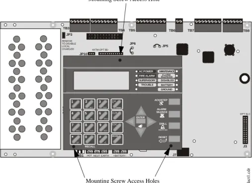
Product Description Controls and Indicators
1.4 Controls and Indicators
LCD Display
The FACP uses an 80-character (4 lines X 20 characters) high viewing angle LCD display. The display includes a long life LED backlight that remains illuminated. If AC power is lost and the system is not in
alarm, the LED backlight will turn off to conserve batteries.
LED Indicators
LED indicators are provided to annunciate the following conditions: • AC Power (green)
• Fire Alarm (red) • Supervisory (yellow) • Trouble (yellow)
• Maintenance/presignal (yellow) • Alarm Silenced signals (yellow) • Disabled (yellow)
• Battery fault (yellow) • Ground fault (yellow)
Key Panel
Mounted on the main circuit board, the key panel includes a window for the LCD display and LED indicators as listed above. The key panel, which is visible with the cabinet door closed, has 25 keys, including a 16 key alpha-numeric pad similar to a telephone keypad.
Function keys:
• Acknowledge/Step • Alarm Silence • Drill
• Reset (lamp test) Service/program keys:
• Keys labeled 1 to 9 • * key
• # key • 0 (recall) key • 1st Event key • Clear key • Escape key • Mode key
• Four cursor keys (up, down, left and right) • Enter key
Local Piezo Sounder
A piezo sounder provides separate and distinct pulse rates for alarm, trouble and supervisory conditions.
FIRE-LITE ALARMS INC
SYSTEM ALL NORMAL
10:00A 020102
1 4 * 2 5 0 3 6 # 1st EVENT ABC DEFGHI JKL MNO
PRS TUV WXY
QZ -/.
CLR
7 8 9 ESC
ENTER RECALL ACK/STEP ALARM SILENCE DRILL
HOLD 2 SEC
RESET MODE MAINTENANCE ALARM SILENCED DISABLED BATTERY GROUND SUPERVISORY TROUBLE AC POWER FIRE ALARM
Figure 1.2 Membrane/Display Panel
9600kypd.c
d
Circuits Product Description
1.5 Circuits
SLC Communication Loop
One SLC loop is provided standard on the FACP main circuit board. A second SLC loop is available by plugging the optional SLC module into connector J3 on the main circuit board. SLC loops, configurable for NFPA Style 4, 6 or 7, provide
communication to addressable detectors, monitor (initiating device) and control (output device) modules. Refer to the SLC Wiring manual for information on wiring devices.
Output Circuits
The following output circuits are available on the FACP:
• 24 VDC Resettable (smoke detector power) output - 3.00 amps maximum • 24 VDC Nonresettable power output #1 - 3.00 amps maximum
• 24 VDC Nonresettable power output #2 - 3.00 amps maximum • 24 VDC Battery Charger (up to 25 AH batteries)
NAC (Notification Appliance Circuits)
Up to four NACs are provided with various programmable features: • four Style Y (Class B) NACs
OR
• two Style Z (Class A) NACs
Relays
One fixed and two fully programmable Form-C dry contact relays are provided. The fixed fail-safe relay monitors system trouble and the two programmable relays are factory default programmed for system alarm and system supervisory. Contacts are rated 2.0 amps @ 30 VDC (resistive) and 0.5 amps @ 30 VAC (resistive). The programmable relays can be programmed for the following operations:
• fire alarm • trouble • supervisory
• supervisory auto-resettable • DACT communication failure • process monitor
• process monitor auto-resettable • hazard alert
• medical alert • AC loss
Auxiliary Trouble Inputs
Auxiliary Trouble Inputs can be connected to trouble bus outputs from auxiliary equipment, such as power supplies or normally-open dry contacts of a trouble relay to allow monitoring by the MS-9600.
1.6 Components
Main Circuit Board
The main circuit board contains the system’s CPU, power supply, other primary components and wiring interface connectors. Optional modules plug in and are
Reference Manual
Product Description Components
Cabinet
The MS-9600 cabinet is red with a navy blue front overlay. The backbox provides space for two batteries (up to 18 Amp Hour). Ample knockouts are provided for system wiring. Also included is a standard dress panel, which mounts to the inside of the cabinet (required by ULC for Canadian applications). The dress panel must be installed to meet FM requirements.
Batteries
The MS-9600 cabinet provides space for two batteries (up to 18 Amp Hour). Batteries larger than 18 Amp Hour up to 25 Amp Hour require use of the Fire•Lite BB-26 or similar UL listed battery cabinet. The CHG-75 can be used for charging 25 to 75 AH batteries and the BB-26 can be used for housing the batteries. The CHG-120F can be used for charging 25 to 120 AH batteries and the BB-55F can be used for housing the batteries. Batteries must be ordered separately.
1.6.1 Intelligent Addressable Detectors: Newer Series
Intelligent, addressable detectors provide information to the control panel on an SLC Signaling Line Circuit (refer to the SLC Wiring Manual for detailed information on device installation, wiring and operation). This allows the control panel to continually process the information to determine the status (alarm, trouble, maintenance or normal) of each detector. Each detector responds to an SLC address that is set in the detector head using built-in rotary decimal switches with the ability to select up to 159 addresses. Note that a blinking LED on an intelligent detector indicates
communication between the detector and the control panel. Refer to the Fire•Lite Device Compatibility Document for a list of approved detectors.
Smoke Detectors (Photoelectric)
The SD350 and SD355 are intelligent, addressable low profile photoelectric smoke detectors which provide smoke sensing technology. The SD350T and SD355T include a 135o fixed thermal sensor. The AD350and AD355 are multicriteria photoelectric
smoke detectors with heat sensing capabilities and automatic drift compensation.
Smoke Detector (Ionization)
The CP350 and CP355 are intelligent, addressable low profile ionization smoke detectors which measure the level of combustion products in their chambers using the ‘ionization principle.’
Smoke Detector (Duct)
The D350P is an intelligent, addressable photoelectric duct smoke detector. The D350RP includes an alarm relay.
Heat Detectors
The H350 and H355 are intelligent heat detectors with thermistor sensing circuits for fast response, designed to provide open area protection with 50 foot (15 m) spacing capability. The H350R and H355R incorporate a thermal Rate-of-Rise circuit of 15oF
(9.4oC). The H355HT is a high temperature heat detector rated for 190oF.
Detector Bases
The B501BH is a standard sounder base and the B501BHT is a temporal tone sounder base for intelligent, addressable smoke detectors.
The B224RB is a relay base with one Form-C relay for intelligent, addressable smoke detectors. It may be used to control auxiliary functions.
The B224BI is an isolator base for intelligent, addressable smoke detectors. It functions similar to the I300 isolator module which allows loops to operate under fault conditions and automatically restore when the fault is removed.
Components Product Description
1.6.2 Intelligent Addressable Modules: Newer Series
The newer series of Control Modules and Monitor Modules provide an interface between the control panel and conventional notification and initiating devices. Each module can be set to respond to an address with built-in rotary switches with the ability to select up to 159 addresses (a tab on the address switch must be broken off to use addresses 100-159). A blinking LED on a monitor module indicates communication between the module and the control panel. These devices are also compatible with older systems. Refer to the Fire•Lite Device Compatibility Document for a list of approved notification and initiating devices.Monitor Modules
The MMF-300, MMF-300-10, MDF-300, MMF-302 and MMF-302-6 are addressable monitor modules for monitoring conventional initiating devices. The MMF-300 is used for normally open contact alarm initiating devices, such as manual pull stations, four-wire smoke detectors, heat detectors, waterflow, security contacts and supervisory devices. The MMF-300-10 functions the same as the MMF-300 except it provides 10 Class B or 5 Class A inputs. The MDF-300 is a dual monitor module (Class B only) which occupies two consecutive SLC addresses, with each module functionally the same as the MMF-300. The MMF-302 is used primarily for two-wire smokes detectors in addition to normally open contact devices. The MMF-302-6 functions the same as the MMF-302 except it provides 6 Class B or 3 Class A inputs. The supervised IDCs (Initiating Device Circuits) can be wired to the modules as NFPA Style B (Class B) or Style D (Class A) circuits. The modules are supplied with a thermoplastic cover for mounting to a 4-inch mounting box.
Monitor Module (miniature)
The MMF-301 is an addressable module that is functionally similar to an MMF-300 but offered in a smaller package for mounting directly in the electrical box of the device being monitored.
Control Module
The CMF-300 and CMF-300-6 are an addressable Control Modules used to connect NACs (Notification Appliance Circuits) to power and supervise compatible, UL-listed notification appliances. The CMF-300 provides one Class B or Class A output while the CMF-300-6 provides 6 Class B or 3 Class A outputs. The NACs can be wired to the module as supervised NFPA Style Y (Class B) or Style Z (Class A) circuits. The modules are supplied with a thermoplastic cover for mounting to a 4-inch square mounting box.
Relay Module
The CRF-300 and CRF-300-6 are a Control Relay Modules which are functionally similar to the CMF-300 but used as Form-C relay modules. The CRF-300 provides one Form-C relay while the CRF-300-6 provides six Form-C relays.
Isolator Module
The I300 loop isolator module is an automatic switch which opens the circuit voltage to the SLC loop branch(es) whenever a wire-to-wire short circuit is detected on that loop. The remainder of the communications loop leading up to the I300 will continue to operate, unaffected by the short. The isolator module is bidirectional, meaning that it can detect a fault condition between the input SLC terminals or output SLC terminals. The I300 is required to meet NFPA Style 7 requirements.
Detector Annunciator
The RA400Z is a remote single LED annunciator that can be wired directly to an
Reference Manual
Product Description Optional Modules
1.6.3 300 Series Intelligent Addressable Devices
Fire•Lite’s 300 Series Intelligent Addressable Devices are fully compatible with the MS-9600 FACP. The devices must be configured for CLIP Mode operation if the control panel is installed in an existing system with 300 Series devices. The address of 300 Series devices cannot be set above 99. Compatible devices include:
• SD300 Photoelectric Detector
• SD300T Photoelectric Detector with Thermal Sensor • CP300 Ionization Detector
• M300 Monitor Module
• M301 Miniature Monitor Module • M302 2-wire Monitor Module • C304 Control/Relay Module • BG-10LX Manual Pull Station
1.6.4 Addressable Device Accessories
End-of-Line Resistor Assembly Fire•Lite P/N R-47K
The 47 kΩ End-of-Line Resistor assembly (P/N: R-47K) is used to supervise the MMF-300, MDF-300, MMF-301 and CMF-300 module circuits. The 3.9 kΩ End-of-Line Resistor assembly is used to supervise the MMF-302 module circuit. The resistors are included with each module.
Power Supervision Relay
The UL listed End-of-Line power supervision relay is used to supervise the power to 4-wire smoke detectors and notification appliances.
N-ELR Mounting Plate
The N-ELR is a single End-of-Line resistor plate which is required for use in Canada. An ELR, which is supplied with each module and fire alarm control panel, is mounted to the ELR plate. Resistors mounted to the N-ELR plate can be used for the supervision of a monitor and control module circuit.
1.7 Optional Modules
The MS-9600 main circuit board includes option module connectors for the following modules:
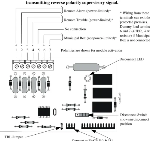
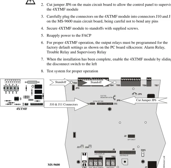
4XTMF Transmitter Module
The 4XTMF provides a supervised output for local energy municipal box transmitter, alarm and trouble reverse polarity. It includes a disable switch and disable trouble LED. A jumper on the module is used to select an option which allows the reverse polarity circuit to open with a system trouble condition if no alarm condition exists. The module plugs into connectors J10 and J11 which are located near the top center of the main circuit board. When the 4XTMF module is installed, Jumper JP6, on the main circuit board, must be cut to allow supervision of the module.
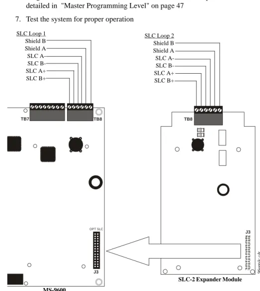
SLC-2 Expander Module
The SLC-2 Expander Module allows expansion of the MS-9600 from one SLC circuit to two SLC circuits. The module plugs into connector J3 which is located in the lower right corner of the main circuit board. The wiring for the second SLC connects to terminals located on the expander module.
DACT-UD Digital Alarm Communicator/Transmitter
The DACT-UD is used to transmit system status to UL-listed Central Station receivers via the public switched telephone network. All circuitry and connectors are contained on a compact module which plugs into connector J2, which is located near the bottom center of the main circuit board.
Accessories Product Description
1.8 Accessories
1.8.1 PK-CD Programming Utility
The PK-CD Programming Utility can be used to program an MS-9600 directly from most IBM compatible computers, including laptops and portables, equipped with a serial port. MS-9600 program files can also be created and stored on the PC and then downloaded to the control panel. The PK-CD Kit includes the MS-9600 Windows-based Programming Utility software on CD-ROM with on-line help file. A serial cable (P/N: PRT/PK-CABLE), which must be purchased separately, is required for
connection of the PC to the RS-232 (PC/Printer) terminals at TB7 of the MS-9600 main circuit board. Refer to the illustration on page 10 and the section titled "Printer/PC" on page 39, for the location and connections to this terminal.
1.8.2 Dress Panel
A dress panel is provided standard with the MS-9600 (required for Canadian installations). The dress panel restricts access to the system wiring while allowing access to the key panel.
Note that the MS-9600 FACP, installed with the dress panel, has received Factory Mutual (FM) approval. FM approval is contingent on the proper installation of the dress panel.
1.8.3 Battery Box
BB-17F
The BB-17F battery box may be used to house up to two 18 AH batteries in the event that room is not available in the main cabinet due to the use of a UDACT-F, 411UD, etc. The battery box mounts directly below the FACP cabinet. The battery box is red and is provided with knockouts.
BB-26
The BB-26 battery box may be used to house up to two 26 AH batteries and the CHG-75 Battery Charger. The battery box is red and is provided with knockouts.
BB-55F
The BB-55F battery box may be used to house two 25 AH batteries, two 60 AH batteries or one 100 AH battery. When the CHG-120F is mounted in the BB-55F, two 25 AH or one 60 AH battery may also be housed in the battery box.
CAUTION: HIGH VOLTAGE UNDER PANEL !! WARNING !! SEVERAL DIFFERENT SOURCES OF POWER CAN BE CONNECTED TO THIS CONTROL UNIT DISCONNECT ALL SOURCES OF POWER BEFORE SERVICING
Product Description Accessories
1.8.4 Battery Charger
1.8.4.1 CHG-75 Battery Charger
The CHG-75 is capable of charging up to 75 AH lead-acid batteries with the MS-9600 FACP. The FACP battery charger must be disabled when using the CHG-75. The charger and up to 26 AH batteries can be housed in the Fire•Lite BB-26 battery box. Larger batteries and the charger can be housed in the Fire•Lite BB-55F battery box which can be mounted up to 20 feet away from the control panel. Refer to the CHG-75 Manual for additional information.
1.8.4.2 CHG-120F Battery Charger
The CHG-120F is capable of charging up to 120 AH lead-acid batteries with the MS-9600 FACP. The FACP battery charger must be disabled when using the CHG-120F. The batteries and charger can be housed in the Fire•Lite BB-55F battery box which can be mounted up to 20 feet away from the control panel. Note that when using the BB-55F for housing the charger and batteries greater than 25AH, multiple BB-55Fs are required. Refer to the CHG-120F Manual for additional information.
1.8.5 Annunciators
ACM Series LED Zone Type Annunciators
The ACM Series Annunciators remotely display alarm and trouble status as well as system status. In addition, they can provide remote Acknowledge, Silence, Reset and Drill functions. For more detailed information, refer to the appropriate annunciator manual. Following is a list of annunciators which can be used with the MS-9600.
• ACM-16ATF* Annunciator Control Module annunciates 16 zones with 16 red
alarm LEDs and 16 yellow trouble LEDs. In addition, it has a System Trouble LED, an On Line/Power LED and a local piezo sounder. It also has switches for FACP Acknowledge, Silence, Reset and Drill. It has rotary address switches and will accept up to three AEM-16ATF Expanders. In Canada, this module must be used to annunciate the fire alarm input points/zones only.
• AEM-16ATF Annunciator Expander Module annunciates 16 zones with 16 red alarm LEDs and 16 yellow trouble LEDs
• AFM-16ATF* Annunciator Fixed Module annunciates 16 zones with 16 red
alarm LEDs and 16 yellow trouble LEDs. In addition, it has a System Trouble LED, an On Line/Power LED and a local piezo sounder. It also has switches for FACP Acknowledge, Silence, Reset and Drill. It is fixed at address ‘1.’ In Canada, this module must be used to annunciate the fire alarm input points/zones only.
• ACM-32AF* Annunciator Control Module annunciates 32 alarm zones with 32
red LEDs. In addition, it has a System Trouble LED, an On Line/Power LED and a local piezo sounder. It also has a switch for local piezo silence. It has rotary address switches and will accept one AEM-32AF Expander. In Canada, this module must be used to annunciate the fire alarm input points/zones only. • AEM-32AF Annunciator Expander Module annunciates 32 alarm zones with 32
red LEDs
• AFM-16AF* Annunciator Fixed Module annunciates 16 alarm zones with 16 red
alarm LEDs. In addition, it has a System Trouble LED, an On Line/Power LED and a local piezo sounder. It also has a switch for local piezo silence. It is fixed at address ‘1.’ In Canada, this module must be used to annunciate the fire alarm input points/zones only.
• AFM-32AF* Annunciator Fixed Module annunciates 32 alarm zones with 32 red
LEDs. In Canada, this module must be used to annunciate the fire alarm input points/zones only.
* In Canada, the color red must be used to indicate active alarm inputs. Yellow indicates supervisory, burglary or trouble signals. Green indicates the presence of power, or an activated output.
Reference Manual
Reference Manual
Getting Started Product Description
LCD-80F Remote Fire Annunciator
The LCD-80F annunciator is a compact 80-character backlit LCD remote fire annunciator that is capable of displaying English language text. It mimics the display on the control panel and will annunciate device type, point alarm, trouble or
supervisory condition, zone assignment plus any custom alpha labels programmed into the FACP. The annunciator also provides system status LEDs to display AC Power, Alarm, Trouble, Supervisory and Alarm Silenced conditions. Additionally, the LCD-80F is capable of remotely performing critical system functions such as Acknowledge, Silence, Reset and Drill.
Communications between the control panel and the annunciator is accomplished over a serial interface employing the EIA-485 communication standard. Up to 32 LCD-80F annunciators may be connected to the EIA-485 circuit. The annunciators may be powered from the host FACP or a remote UL listed filtered power supply such as the Fire•Lite FCPS Series. For more detailed information, refer to the LCD-80F manual.
LDM Series Lamp Driver Modules (Graphic Annunciator)
The LDM Series Lamp Driver Modules, which consist of the LDM-32F master and LDM-E32F expander modules, are used to provide an interface to a custom graphic LED annunciator. The master module provides power and control for a maximum of three expander modules. The LDM-32F and LDM-E32F have output connectors which are used to drive lamps or LEDs and input connectors which are used for remote switch functions. Refer to the LDM Series Lamp Driver Modules manual for a complete description.
1.9 Getting Started
The following is a brief summary of the minimal steps involved in bringing an MS-9600 on-line:
• Install Backbox and Main Circuit Board (refer to "Mounting" on page 24) • Address and Install Intelligent Devices (refer to the SLC Wiring Manual) • Enter Autoprogramming (refer to "Autoprogram" on page 48)
• Resolve Programming Conflicts
• Go to Point Program to Enter Specific Data (refer to "Point Program" on page 49). Use the right and left arrow keys to navigate between devices.
Reference Manual
Reference Manual
Installation Mounting
SECTION 2
Installation
The cabinet may be either semi-flush or surface mounted. The cabinet mounts using two key slots and two 0.250” (6.35 mm) diameter holes located in the backbox. The key slots are located at the top of the backbox and the two securing holes at the bottom. Carefully unpack the system and check for shipping damage. Mount the cabinet in a clean, dry, vibration-free area where extreme temperatures are not encountered. The area should be readily accessible with sufficient room to easily install and maintain the panel. Locate the top of the cabinet approximately 5 feet (1.5 m) above the floor with the hinge mounting on the left. Determine the number of conductors required for the devices to be installed. Sufficient knockouts are provided for wiring convenience. Select the appropriate knockout(s) and pull the conductors into the box. All wiring should be in accordance with the National and/or Local codes for fire alarm systems.
2.1 Mounting
The circuit board contains static-sensitive components. Always ground yourself with a proper wrist strap before handling any boards so that static charges are removed from the body. Use static suppressive packaging to protect electronic assemblies.
Mark and predrill holes in the wall for the top two keyhole mounting bolts using the dimensions illustrated in Figure 2.2 on page 25
Install two upper fasteners in the wall with the screw heads protruding
Using upper ‘keyholes,’ place backbox over the two screws, level and secure
Mark and drill the lower two holes
Install remaining fasteners and tighten
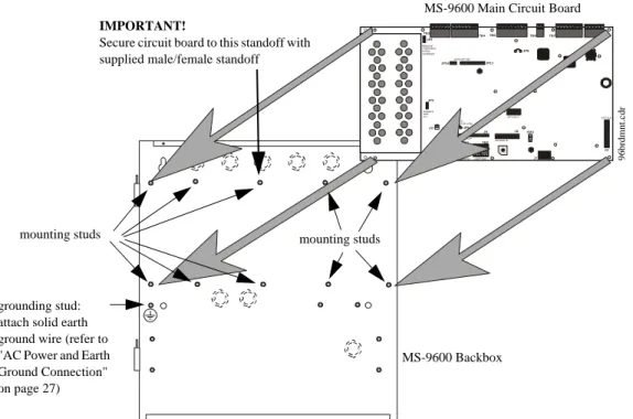
Screw supplied standoffs onto mounting studs in locations indicated below
Attach solid earth ground wire to grounding stud as indicated in Figure 2.1
When the location is dry and free of construction dust, install the main circuit board by aligning the 10 mounting holes in the circuit board with the 10 mounting standoffs in the backbox as illustrated below
Secure the circuit board to the standoffs with the supplied screws and male/ female standoff as indicated in following figure
!
See Page
+BATTERY-LCD DISPLAY KEYPAD I/F
OPT DACT
HOT
CB1
J3 J2
TB1 TB2 TB3
JP3
JP2
SW1 JP5
JP6 J17 J16
J6 J8 J7 JP10 JP11
REMOVE TODISABLE LOCAL CHARGER
DISABLE GND FLT
CUT TO MONITOR 4XTM
OPT SLC 4XTM OPT BD
TB4TB5 TB6 TB7 TB8
NEUT EARTH
Figure 2.1 MS-9600 Main Circuit Board Installation MS-9600 Backbox
MS-9600 Main Circuit Board
mounting studs mounting studs
96brdmnt
.c
dr
IMPORTANT!
Secure circuit board to this standoff with supplied male/female standoff
grounding stud: attach solid earth ground wire (refer to "AC Power and Earth Ground Connection" on page 27)
Mounting Installation
1.75“
4.45 cm
3.79 cm
3.81 cm 1.50“ (3.81 cm)
1.50“ 15.5“ (39.37 cm)
47.0cm 18.5“
1.50“ 3.81 cm
1.50“ (3.81 cm) 1.75“ 4.45 cm
11.1 cm 4.37“ 12.00“ (30.48 cm)
1.62“ (4.11 cm) 1.49“
4.1 cm
1.62“ 4.1cm1.62“
1.75“ 2.00“ 2.00“
2.00“ 2.00“ 2.00“ 5.1 cm 2.00“
10.0“ 25.4 cm
4.37“ 11.1 cm 17.35 cm
6.83“
4.1cm 1.583“ 4.45cm 1.75“ 4.45cm 1.75“ 1.453“ (3.69 cm)
9600enc
Installation Mounting
Top
Left Side Right Side
Bottom
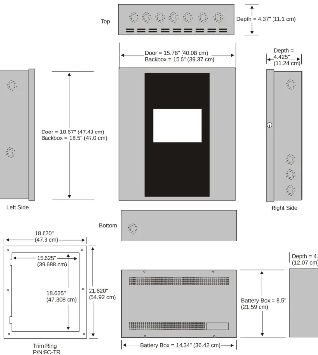
Depth = 4.75" (12.07 cm)
Battery Box = 8.5" (21.59 cm)
Battery Box = 14.34" (36.42 cm) Trim Ring
P/N:FC-TR
21.620" (54.92 cm) 18.625"
(47.308 cm) 15.625" (39.688 cm) 18.620" (47.3 cm)
Door = 18.67" (47.43 cm) Backbox = 18.5" (47.0 cm)
Depth = 4.425" (11.24 cm) Door = 15.78" (40.08 cm)
Backbox = 15.5" (39.37 cm)
Depth = 4.37" (11.1 cm)
Figure 2.3 MS-9600 Cabinet Dimensions
9600ca
Power Installation
2.2 Power
WARNING: Several different sources of power can be connected to this panel.
Disconnect all sources of power before servicing. The panel and associated equipment may be damaged by removing and/or inserting cards, modules or interconnecting cables while this unit is energized.
2.2.1 AC Power and Earth Ground Connection
Primary power required for the FACP is 120 VAC, 50/60 Hz, 3.2 amps for the MS-9600 or 220/240 VAC, 50/60 Hz, 1.6 amps for the MS-9600E. Overcurrent protection for this circuit must comply with Article 760 of the National Electrical Code (NEC) and/or local codes. Use 14 AWG (2.00 mm2) or larger wire with 600 volt insulation rating.Make certain that the AC mains circuit breaker is off before
wiring any connections between the mains and the control panel. Connect wiring from the AC mains to TB1 on the FACP, being careful to observe proper connections. Connect a wire from the grounding stud in the cabinet to a known solid earth ground (refer to Figure 2.1 on page 24). This connection is vital for maintaining the control panel’s immunity to unwanted transients generated by lightning and electrostatic discharge. Apply AC power to the panel only after the system is completely installed and visually checked. Note that AC power must be applied to the panel before installing the battery interconnect cable (refer to the following section).
2.2.2 Battery Power
Before connecting the batteries to the FACP, make certain that the interconnect cable between the batteries is not connected. Do not connect the interconnect cable until the system is completely
installed. Observe polarity when connecting the batteries. Connect the battery cable to TB2 on the main circuit board. Refer "Power Supply Calculations" on page 136, for calculation of the correct battery rating.
WARNING: Battery contains sulfuric acid which can cause severe burns to the skin
and eyes and can destroy fabrics. If contact is made with sulfuric acid, immediately flush the skin or eyes with water for 15 minutes and seek immediate medical attention.
2.2.3 DC Power Output Connection
All DC power outputs are power-limited.+BATTERY-LCD DISPLAY
HOT
B1
TB1 TB2
J6
NEUT EARTH
-- +
+
Interconnect Cable
See Page
+ + + -Power-limited Resettable Power
3.0 amperes max., 24 VDC nominal filtered, resettable power can be drawn from TB3 Terminals 1(+) and 2(-)
Power-limited Nonresettable Power #1
3.0 amperes max. , 24 VDC nominal filtered, nonresettable power can be drawn from TB3 Terminals 3(+) and 4(-)
Power-limited Nonresettable Power #2
3.0 amperes max. , 24 VDC nominal filtered, nonresettable power can be drawn from TB3 Terminals 5(+) and 6(-)
Installation Relays
2.3 Relays
The FACP provides two programmable Form-C relays and one fixed fail-safe Form-C trouble relay, all with contacts rated for 2.0 amps @ 30 VDC (resistive) or 0.5 amps @ 30 VAC (resistive). The Alarm and Supervisory silk-screen labels reflect the factory default programming for the two programmable relays.
Note that relay connections may be power-limited or nonpower-limited, provided that 0.25” spacing is maintained between conductors of power-limited and nonpower-limited circuits. Refer to UL Power-nonpower-limited wiring requirements.
2.4 Notification Appliance Circuits
The control panel provides four Style Y/Class B or two Style Z/Class A NACs (Notification Appliance Circuits). Each circuit is capable of 3.0 amps of current. Total system current in alarm cannot exceed 7.0 amps (refer to "Calculating the System Current Draw" on page 137). Use UL listed 24 VDC notification appliances only. Circuits are supervised and power-limited. Refer to the Fire•Lite Device Compatibility Document for a listing of compatible notification appliances. The NACs, which are located on the main circuit board, may be expanded via the Fire•Lite FCPS Series field charger/power supplies.
The following sections describe the configuration and wiring of Style Y and Style Z Notification Appliance Circuits on the MS-9600 main circuit board. The NACs are configured for Style Y (Class B) from the factory. Refer to "Configuring NACs" on page 29 for information on changing the NAC configuration to Style Z (Class A) and preparing the NACKEY configuration card located in JP8, when installing a 4XTMF Transmitter Module.
ALARM RELAY
NONC C NCNO C NONC C
SUPV RELAY TROUBLE
RELAY
Figure 2.5 Relay Terminals
Relay contacts shown with power applied to panel and no active troubles, alarms or supervisories
TB5 Note that the relays labeled as Alarm
Relay (Relay 1) and Supervisory Relay (Relay 3) reflect the factory default programming for these relays which are programmable.
The relay labeled Trouble Relay (Relay 2) is fixed and cannot be changed. It is a fail-safe relay which will transfer on any trouble or total power failure.
9600r
eyp.cdr
Reference Manual See Page
Notification Appliance Circuits Installation
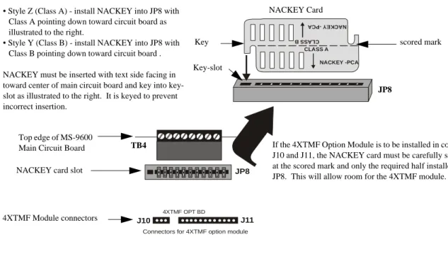
2.4.1 Configuring NACs
The Notification Appliance Circuits on the main circuit board are configured for Style Y or Style Z by properly orienting the NACKEY card in JP8 which is located at the top of the main circuit board near the NAC Terminal TB4. The default configuration is for Style Y (Class B). Refer to Figure 2.6 for information on installing the NACKEY card.
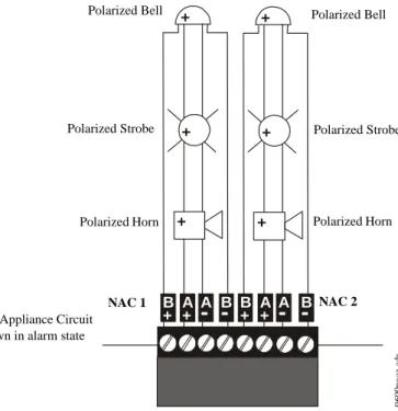
2.4.2 Style Y (Class B) NAC Wiring
J10 J11
4XTMF OPT BD
JP8
Connectors for 4XTMF option module
CLASS A
CLA SS B
NACKEY -PCA
NAC KEY -P CA
Figure 2.6 NAC Configuration Using NACKEY NACKEY Card
JP8
Top edge of MS-9600 Main Circuit Board
• Style Z (Class A) - install NACKEY into JP8 with Class A pointing down toward circuit board as illustrated to the right.
• Style Y (Class B) - install NACKEY into JP8 with Class B pointing down toward circuit board .
NACKEY must be inserted with text side facing in toward center of main circuit board and key into key-slot as illustrated to the right. It is keyed to prevent incorrect insertion.
TB4 If the 4XTMF Option Module is to be installed in connectors J10 and J11, the NACKEY card must be carefully separated at the scored mark and only the required half installed into JP8. This will allow room for the 4XTMF module.
scored mark
4XTMF Module connectors NACKEY card slot
Key
Key-slot
B
+ B
-
B+ B-1 1
-+ +
+ +
+ +
+ +
+ +
+ +
B
+ B
-
B+ B-3 -3 2 4 4 2
4 Style Y (Class B) Notification Appliance Circuits, supervised and power-limited - 4.7 kohm, ½ watt P/N:71252 UL listed
Polarized Bells Polarized Bells
Polarized Horns Polarized Horns
Polarized Strobes
Notification Appliance Circuit polarity shown in alarm state
Dummy Load all unused circuit
y
.c
dr
Polarized Strobes
circuit number
Installation Notification Appliance Circuits
2.4.3 Style Z (Class A) NAC Wiring
B
+ A+ A
-
B-
B+ A+ A-
B-+ +
+ +
+ +
2 Style Z (Class A) Notification Appliance Circuits, supervised and power-limited
Polarized Bell
Polarized Horn Polarized Horn
Notification Appliance Circuit polarity shown in alarm state
Polarized Bell
Polarized Strobe Polarized Strobe
Figure 2.8 NAC Style Z (Class A) Wiring
9600nac
z.c
dr