Electrical Engineering Vol. 17, No. 2, pp. 163{174
c
Sharif University of Technology, December 2010
Simultaneous Coordinated Tuning of
SSSC-Based Stabilizer and PSS Using
Quadratic Mathematical Programming
M.R. Shakarami
1;and A. Kazemi
1Abstract. In a Static Synchronous Series Compensator (SSSC), a controllable AC voltage is generated by a voltage-source converter. There are two control channels for controlling the magnitude and phase of the voltage. When this device is used for damping inter-area oscillations in multi-machine power systems, a damping stabilizer can be included in both channels. In this paper, a method for the simultaneous coordinated design of a Power System Stabilizer (PSS) and a SSSC-based stabilizer is presented using quadratic mathematical programming. In this method, the gain and phase of a lead-lag stabilizer can be simultaneously calculated. By this method the eect of the SSSC-based stabilizer in both control channels on damping inter-area oscillations has been assessed. Obtained results including eigenvalue analysis and non-linear simulations, on two multi-machine power systems under dierent operating conditions, show that the usage of a SSSC stabilizer in a suitable control channel can signicantly reduce the control cost of the stabilizer.
Keywords: Damping stabilizer; Inter-area oscillations; SSSC; PSS; Quadratic mathematic program-ming.
INTRODUCTION
The damping of power system oscillations between inter-connected areas is very important for secure operation of the system [1]. Conventionally, Power System Stabilizers (PSSs) are used for damping power system oscillations. The damping of inter-area oscil-lations may be reduced signicantly in stressed power systems [2]. In this case, the use of PSSs may not only be eective in providing sucient damping for inter-area oscillations [3]. While PSSs have the capa-bility to damp local modes, series power electronics-based FACTS stabilizers have become amongst the best alternative means to improve damping inter-area oscillations. However, interactions between PSSs and FACTS-based stabilizers may enhance or degrade the damping of certain oscillation modes. Therefore, coordinated parameter design of PSSs and FACTS
1. Department of Electrical Engineering, Iran University of Science and Technology, Tehran, P.O. Box 16846, Iran. *. Corresponding author. E-mail: [email protected] Received 9 September 2009; received in revised form 29 December 2009; accepted 16 February 2010
stabilizers is necessary to improve overall system per-formance. SSSC is one of the series FACTS devices that in addition to increasing transferred power can improve the stability of power systems [4-7]. The SSSC, in comparison with other FACTS devices, is more eective for damping mechanical oscillations [8]. The SSSC injects a set of balanced voltages to the transmission line quadrature with the line current. There are two control channels to control the magnitude and phase of the voltage, which are magnitude control and phase control channels. When the SSSC is used for damping mechanical oscillations, the damping stabilizer can be included in both channels. Most studies are done on SSSC magnitude-based stabilizers [9-13]. It seems that the SSSC phase-based stabilizer is not basically studied in reported literature. Therefore, the eect of a SSSC-based stabilizer in dierent control channels on damping inter-area oscillations in multi-machine power systems needs to be evaluated.
One eective method in designing damping stabi-lizers in FACTS devices is linear programming [14,15]. However, in these papers, the rst phase of a stabilizer has been calculated and, assuming that the stabilizer
phase remains constant in the frequency range of oscillation modes, using linear programming the gain of the stabilizer has been calculated. This assumption may not be true [16]. In [17], the gain and phase of a PSS have simultaneously been calculated using mathematic programming. In this paper, it is supposed that the phase of the residue is positive therefore, PSS must have a lead phase structure. However, in some cases particularly in FACTS-based stabilizers the phase of the residue can be negative and the stabilizer must have a lag structure.
In this paper, a SSSC-based stabilizer is investi-gated in order to improve damping inter-area oscilla-tions in multi-machine power systems. In addition to a magnitude-based stabilizer, a phase-based stabilizer is presented for SSSC. A method based on quadratic mathematic programming to design a phase-lead or a phase-lag damping stabilizer has been presented. This method is used for simultaneous parameter design of a SSSC-based stabilizer and a PSS to improve the dynamic stability of power systems. By this method, the eect of dierent stabilizers of SSSC on damping inter-area oscillations in two machine power systems under dierent operating conditions has been analyzed and compared.
POWER SYSTEM MODEL Generator
In this study, the generators are represented by a forth-order d q axis model. In this case, nonlinear dynamic equations for each generator with known variables are [18]:
_ = ! !s; (1)
M _! = Pm Pe D
! !s 1
; (2)
T0
d0 _Eq0 = E0q (Xd Xd0)Id+ EF D; (3)
T0
q0 _Ed0 = E0d+ (Xq Xq0)Iq; (4)
Pe= (IdEd0 + IqEq0) + (Xq0 Xd0)IdIq; (5)
where , !, !s, M, D and Pm are angle, speed,
synchronous speed, inertia, damping coecient and input mechanical power of the machine, respectively; xd, xq, id, iq, x0d and x0q are d-axis reactance,
q-axis reactance, d-q-axis current, q-q-axis current, d-q-axis transient reactance and q-axis transient reactance, respectively; T0
doand Tqo0 are q- and d open circuit time
constant, respectively; EF Dis the led voltage, and Eq0
and E0
d are the quadrature and direct axis component
of transient voltage, respectively.
Exciter
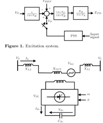
The IEEE type-AC-4A excitation system is considered in this work. Its block diagram is shown in Figure 1. The role of used parameters for the system is discussed in [19]. For stability improvement, the exciter of each generator can be equipped with a PSS, as shown in Figure 1, where VT and VREF are the terminal voltage
of the generator and reference of voltage regulator, respectively. KA is gain and TR, TA, TB and TC are
time constants related to the excitation system. SSSC Modeling
It is assumed that in a multi-machine power system a SSSC is installed on the transmission line between nodes 1 and 2, as shown in Figure 2.
The SSSC consists of a Series Coupling Trans-former (SCT) with the leakage reactance, XSCT, a
three-phase GTO based Voltage Source Converter (VSC) and a DC capacitor. The SSSC can be described as [9]:
Vinj= mkVdc(cos + j sin ); (6)
IL= ID+ jIQ = jILj \ ; (7)
dVdc
dt = mk
Cdc(IDcos + IQsin ); (8)
where Vinj is the ac injected voltage by the SSSC; m
and are the modulation ratio and phase dened by
Figure 1. Excitation system.
Pulse Width Modulation (PWM), respectively; k is the ratio between the ac and dc voltage depending on the converter structure; Vdc is the dc voltage; Cdc is
the dc capacitor value, and ID and IQ are D-and Q
components of the line current IL, respectively.
SSSC-BASED STABILIZERS Phase-Based Stabilizer
Assuming a lossless SSSC, the ac voltage is kept in quadrature with the line current so that the SSSC only exchanges reactive power with the transmission line. By adjusting the magnitude of the injected voltage, the reactive power exchange can be controlled. When the SSSC voltage lags the line current by 90, it
emulates a series capacitor. It can also emulate a series inductor when the voltage leads the line current by 90.
Thus, a SSSC can be considered as a series reactive compensator where the degree of compensation can be varied by controlling the magnitude of the injected voltage. In this paper, the SSSC is considered in capacitor mode. To keep the injected voltage in quadrature with the line current, a PI controller, as shown in Figure 3, has been used. Here, ref is the
phase of the injected voltage in steady-state and its value is considered ref = 90 + ss where ss is
the angle of the line current in steady-state; Ts is
time constant of the converter, and KP and KI are
the proportional and integral gain of the PI controller, respectively. A lead-lag stabilizer for damping inter-area oscillations is included in the PI controller. In this case the stabilizer is called the phase-based stabilizer and, for convenience in this paper, it is called the -based stabilizer. In this stabilizer, TW is washout
time constant usually in the range of 1 to 15 s. To design the stabilizer, usually the value of T is assumed as pre-specied, and x2, x1 and x0 are parameters to
be determined. In this paper, the adopted value of T for the stabilizer is considered according to the typical
Figure 3. SSSC phase controller with a damping stabilizer.
values in the studied literature, especially the typical value for PSS presented in [18,19].
The feedback signal for the stabilizer is selected among local signals such as the current, the line-real power and the line-reactive power.
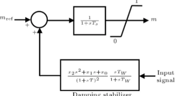
Magnitude-Based Stabilizer
To control the magnitude of the injected voltage, modulation ratio m can be controlled. Figure 4 shows the block diagram of the controller in this case where mref is the value of modulation ratio in steady state.
A stabilizer for the damping of inter-area oscillations is included in the magnitude controller. This stabilizer is called the m-based stabilizer.
STABILIZER DESIGN
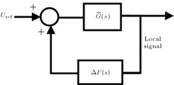
The method adopted in this work to design a SSSC stabilizer is an incremental method. This method is summarized as follows. In the rst step, the closed-loop system is considered, as in Figure 5, where G(s) and F (s) are the power system transfer matrix and the stabilizer transfer matrix, respectively. In the second step, the stabilizer transfer matrix is changed by F . In this case, the closed-loop system changes, as shown in Figure 6, where G(s) is the transfer matrix of the inner loop between G(s) and F (s). In these gures, Uref is considered as the input signal of the system. In
the SSSC-based stabilizer in the phase control channel, Urefis replaced by Vdcref, and in the magnitude control
channel, it is replaced by mref. For a PSS, Uref is
replaced by VREF. One of the local signals is selected
Figure 4. SSSC magnitude controller with a damping stabilizer.
Figure 6. Closed-loop system in the second step.
as the feedback signal for SSSC-based stabilizers. For a PSS, the generator acceleration power is chosen as the feedback signal. The value of F is calculated to shift eigenvalues of critical modes to desired values.
In the following, a procedure for the calculation of F is presented. Assuming that the variation of F is suciently small, the variation of the eigenvalue, i,
can be approximated as:
i=
ns
X
q=1
iqfq(i); (i = 1; 2; ; n); (9)
where n is the number of critical eigenvalues; nsis the
number of stabilizers and iq is the residue associated
to the ith eigenvalue i of G(s) for the qth stabilizer.
Equation 9 can be rewritten as:
i=
ns
X
q=1
fRe(iq)Re(fq(i))
Im(iq)Im(fq(i))g
+ j
ns
X
q=1
fRe(iq)Im(fq(i))
+ Im(iq)Re(fq(i))g: (10)
It is assumed that the qth stabilizer has a lead-lag structure as follows:
fq(s) = xq2s 2+ xq
1s + xq0
(1 + sTq)2
sTw
1 + sTw: (11)
By substituting s = i and xqz= xqz(z = 1; 2; 3) in
Equation 11, the real and imaginary part variations of fq(i) are:
Re(fq(i)) = R2qixq2+ R1qixq1+ R0qixq0;
(12) Im(fq(i)) = I2qixq2+ I1qixq1+ Ioqixq0;
(13) where R0qi, R1qi, R2qi, I0qi, I1qi, and I2qi are specied
values. To shift critical eigenvalues to the left of the
imaginary axis, we must have:
Re(i) jij ; (14)
j!ij Im(i) j!ij ; (15)
where i and !i are the desired shift value of
the real part and acceptable frequency variations of the critical eigenvalue, i, respectively. Substituting
Equations 12 and 13 in Equation 10, we can obtain i as a linear function from xq2, xq1 and xq0.
Substituting the real part of i in Equation 14 and
its imaginary part in Equation 15 then yields:
ns
X
q=1
f2qixq2+ 1qixq1+ 0qixq0g jij ;
(16) j!ij
ns
X
q=1
f2qixq2+ 1qixq1+ 0qixq0g
j!ij ; (17)
where 0qi, 1qi, 2qi, 0qi, 1qi and 2qi are specied
values. On the other hand, if the angle of residue, qi, is positive, the qth stabilizer must have a
phase-lead characteristic, otherwise it must have a phase-lag characteristic.
Considering s = sTq, _xq2 = xq2=(xqoTq2) and _x
q1 = xq1=(xq0Tq), and substituting them in
Equa-tion 11 yields: fq(s) = xq0
_x
q2s2+_xq1s + 1
(1 + s)2
Tws
Tq+ Tws: (18)
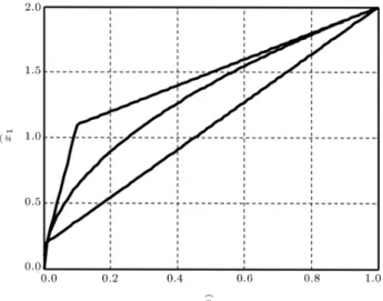
According to [20] for a phase-lead structure, it is assumed that zeroes of fq(s) are almost one-decade nearer to the center than that of its poles, i.e. they belong to interval [ 1 0:1], and for the phase-lag structure, the zeroes are almost one-decade farther to the center, i.e. they belong to interval [ 10 1]. This subject is graphically shown for lead and lag structures in Figures 7 and 8, respectively. In these gures, the points inside the triangles and above the parabolas correspond to the above intervals. To represent the constraints as a linear function, the parabolas are approximated by lines. In this case, the zeroes may be complex values, but the real parts of the complex zeroes are located in the above intervals.
According to Figure 7, the constraints for a phase lead structure can be written as:
_x
q1 _xq2 1; (19)
_x
q1 0:1_xq2 10; (20)
Figure 7. Region corresponding to phase-lead stabilizer.
Figure 8. Region corresponding to phase-lag stabilizer.
As illustrated in Figure 8, the constraints for the phase lag stabilizer are:
_x
q1 _xq2 1; (22)
10_xq1 100_xq2 1; (23)
99_xq1+ 180_xq2 18: (24)
Substituting_xq2 and_xq1 in Equations 19 to 24, and
assuming xqz = xqz + xqz(z = 1; 2; 3) where xq0,
xq1 and xq2 are known values, the constraints can be
rewritten for the lead structure as Equations 25 to 27, and for the lag structure as Equations 28 to 30:
xq2+ Tqxq1 Tq2xq0 xq2
Tqxq1+ Tq2xq0; (25)
xq2+ 10Tqxq1 100Tq2xq0 xq2
10Tqxq1+ 100Tq2xq0; (26)
18xq2 99Tqxq1+ 180Tq2xq0 18xq2
+ 99Tqxq1 180Tq2xq0; (27)
xq2+Tqxq1 Tq2xq0 xq2 Tqxq1+Tq2xq0;(28)
100xq2+ 10Tqxq1 Tq2xq0 100xq2
10Tqxq1+ Tq2xq0; (29)
180xq2 99Tqxq1+ 18Tq2xq0 180xq2
+ 99Tqxq1 18Tq2xq0: (30)
The following function, as the gain of the stabilizer at the frequency !p, p = 1; 2; ; N, is considered to be
the objective function [17]: J = minXN
p=1 ns
X
q=1
jfq(j !p)j2; (31)
where !1; !2; ; !N are a set of frequencies in the
region where the critical eigenvalue must be shifted. By substituting Equation 11 in Equation 31 and considering s = j !p and X = X + X, we can easily
rewrite the objective function as:
J = min12XTHX + fTX; (32)
where the matrix H, vector f and vector X are known, and X is the unknown vector to be tuned where:
X =xns2 xns1 xns0 x12 x11 x10
T;
X =
xns2 xns1 xns0 x12 x11 x10
T : Equation 32 with Equations 16 to 17, and Equations 25 to 27 or Equations 28 to 30 is as a quadratic mathemat-ical programming problem. To solve this problem, the quadprog algorithm provided by the Matlab Optimiza-tion Toolbox is applied here. The proposed approach is an iterative method. In this method, the calculated vector of X is added to the known vector, X, and it is considered as a known vector in the next iteration. The vector, X, in the rst iteration is set to be zero.
SIMULATION RESULTS
Two-Area Four-Machine Power System
A single line diagram of the system is shown in Figure 9. Data of this system are represented in [21]. The loads are modeled as constant impedances. To increase transferred power, the load in area 2 has been increased and the load in area 1 has then been modied to achieve a given tie-line transferred power.
A local signal with maximum residue for inter-area mode is selected as a feedback signal for the damping stabilizer. Figure 10 shows the magnitude of residues as a function of transmitted power for dierent local signals. It can be concluded from this gure that: i) When the stabilizer is included in the phase control channel (the -based stabilizer), the residues for the inter-area mode for dierent local feedback signals are higher than those for cases when the stabilizer is included in the magnitude control channel (the m-based stabilizer).
ii) Variation of the current in the transmission line, where the SSSC is installed, is the best signal for both stabilizers.
Typically, operation conditions presented in Ta-ble 1 are considered. The parameters of the PI controller are calculated as follows.
To obtain a suitable response for the system at a certain operation condition, for a positive value of
Figure 9. One-line diagram of the 4-machine power system.
Figure 10. Magnitude of residue for inter-area mode. Solid line: SSSC phase-based stabilizer; dashed line: SSSC magnitude-based stabilizer.
KI, the value of KP is increased so that the modes
related to the phase-controller (controller modes) are stable. Also, the PI controller must not have signicant degraded eects on damping mechanical oscillations. Then, the values that are suitable for all consid-ered operation conditions are selected. For operation conditions presented in Table 1, KP and KI are
approximately calculated as 200 KI 450 and
25 KP 120.
Considering KP = 25 and KI = 200, the
open-loop oscillation modes in dierent operating conditions are shown in Table 2. It is clear that the damping ratio of the inter-area mode is low and the damping ratio of local mode 1 is not sucient. To control inter-area
Table 1. Considered operating conditions. Operating Condition Characteristics
1 Transmitted power = 410 MW without any line outage
2 Transmitted power = 380 MW and outage one of lines between nodes 4 and 6 3 Transmitted power = 410 MW and outage one of lines between nodes 3 and 4
Table 2. Open-loop oscillation modes and their damping ratio.
Mode Case 1 Case 2 Case 3
Local mod 1 1:243 j7:744 (15:85%) 1:146 j7:769 (14:59%) 1:242 j7:744 (15:84%) Local mod 2 1:559 j7:534 (20:26%) 1:766 j7:643 (22:51%) 1:186 j6:853 (17:05%) Inter-area mode 0:0469 j1:838 (2:551%) 0:080 j1:561 (5:19%) 0:013 j1:794 (0:725%)
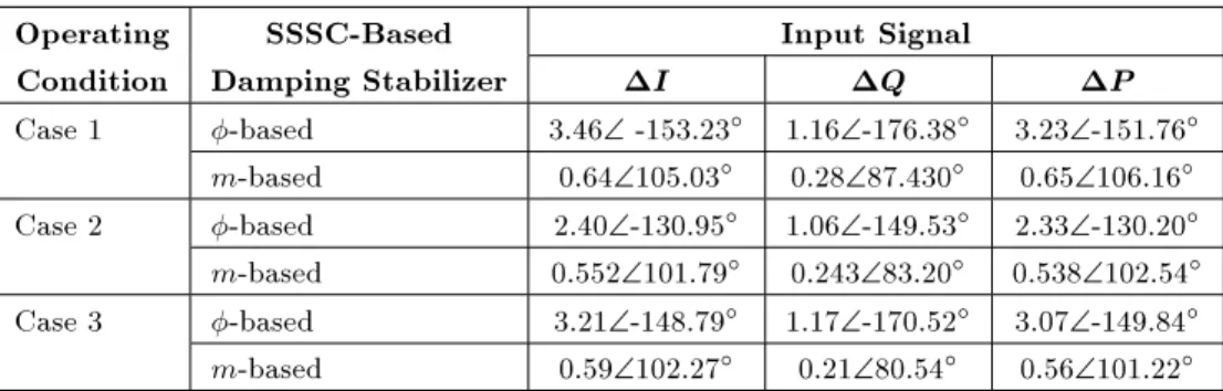
Table 3. Residues for inter-area mode for dierent signals. Operating SSSC-Based Input Signal
Condition Damping Stabilizer I Q P Case 1 -based 3.46\ -153.23 1.16\-176.38 3.23\-151.76
m-based 0.64\105.03 0.28\87.430 0.65\106.16
Case 2 -based 2.40\-130.95 1.06\-149.53 2.33\-130.20
m-based 0.552\101.79 0.243\83.20 0.538\102.54
Case 3 -based 3.21\-148.79 1.17\-170.52 3.07\-149.84
m-based 0.59\102.27 0.21\80.54 0.56\101.22
oscillations, a SSSC is installed in the tie-line between nodes 5 and 6. Specic parameters used for the SSSC are given in the Appendix. Participation factors show that generators 1 and 2, especially generator 1, have the highest contribution to local mode 1. Generator 1 also has the highest contribution in the inter-area mode. A PSS to improve the damping ratio of the local mode is added to the exciter of generator 1. This PSS can sig-nicantly aect the inter-area mode. Therefore, coordi-nation of PSS and SSSC-based stabilizers is necessary. Table 3 shows residues for the inter-area mode under dierent operating conditions. This table shows that in some cases, the phase of residues is negative, therefore, the stabilizer must have a lag structure and, in other cases, it must have a lead structure. Also, this table conrms that the values of the residues for the SSSC-based stabilizer in the phase control channel are higher than those of the magnitude control channel.
In the following, the parameters of PSS and SSSC stabilizers are simultaneously calculated by the proposed method. It is assumed that the desired damping ratio for the inter-area and the local mode in each operating condition is = 20%. According to the frequency of oscillation modes in the open-loop system, the value of !q in Equation 31 has been
considered !q = 1, 5, 8, and the time constants of the
stabilizers for SSSC and PSS are set as T = 0:4 and 0.1, respectively. Also, the eects of stabilizers on other modes must be considered, so that the damping ratios of other modes have been increased, or do not become less than a specic value, and the variations of their frequencies must be acceptable.
To improve the damping ratios of the inter-area mode and local mode 1 to desired values, the parameters of the proposed SSSC-based stabilizers and PSS are calculated and shown in Tables 4 and 5. For comparison of SSSC-base stabilizers, the norm-1 is calculated according to the following equation:
ns
X
q=1
jfq(j!))j : (33)
Norm-1 at dierent values of ! is shown in Table 6. The
Table 4. Parameters of SSSC m-based stabilizer and PSS, 4-machine power system.
Operating
Condition Stabilizer x2 x1 x0 Case 1 SSSC 0.2064 0.1032 0.0129
PSS 0.0152 0.1667 0.1516 Case 2 SSSC 0.0919 0.0459 0.0058 PSS 0.0078 0.1457 0.6847 Case 3 SSSC 0.2318 0.1159 0.0145 PSS 0.0152 0.1663 0.1512
Table 5. Parameters of SSSC -based stabilizer and PSS, 4-machine power system.
Operating
Condition Stabilizer x2 x1 x0 Case 1 SSSC 0.0021 0.0205 0.13700
PSS 0.0067 0.0930 0.3100 Case 2 SSSC 0.0006 0.0095 0.0335 PSS 0.0082 0.1464 0.6503 Case 3 SSSC 0.0019 0.0389 0.1372 PSS 0.0089 0.1465 0.5756
results show that for the same desired damping ratio, norm-1 in the case of the SSSC -based stabilizer is less than in the case of the m-based stabilizer.
Oscillation modes in the closed-loop system are shown in Tables 7 and 8. Comparing eigenvalues in open and closed- loop systems shows that damping ratios of the inter-area mode and the local mode have been improved to the desired values. In addition, it can be seen that other modes have not been degraded signicantly.
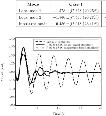
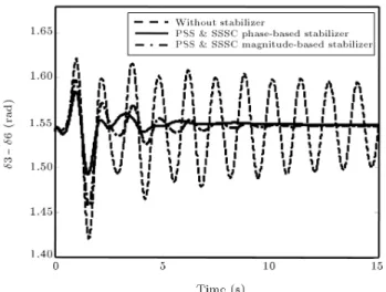
For completeness and verication of the designed stabilizers, a three-phase fault is applied to the test system at bus 6 with fault duration of 0.02 s. The fault is cleared without line switching. Since generators 1 and 3 have the highest contribution to the inter-area mode, the swing angle of generator 1 with respect to generator 3 is shown in Figures 11 to 13. These gures
Table 6. The values of norm-1 at dierent values of !, 4-machine power system. Operating PSS and SSSC
m-Based Stabilizer
PSS and SSSC -Based Stabilizer Condition ! (rad/s) ! (rad/s)
2 5 8 2 5 8
Case 1 0.8435 1.726 2.1314 0.4081 0.4156 0.4740 Case 2 0.9156 1.1629 1.2435 0.6793 0.6957 0.7250 Case 3 0.9056 1.8518 2.2746 0.6829 0.6934 0.7424
Table 7. Closed-loop oscillation modes and their damping ratio in the case of PSS and SSSC m-based stabilizer. Mode Case 1 Case 2 Case 3
Local mod 1 1:575 j7:341 (20:98%) 1:549 j7:779 (19:52%) 1:572 j7:342 (20:94%) Local mod 2 1:567 j7:529 (20:38%) 1:770 j7:640 (22:57%) 1:215 j6:837 (17:497%) Inter-area mode 0:404 j1:795 (21:93%) 0:381 j1:784 (20:88%) 0:370 j1:685 (21:45%)
Table 8. Closed-loop oscillation modes and their damping ratio in the case of PSS and SSSC -based stabilizer. Mode Case 1 Case 2 Case 3
Local mod 1 1:578 j7:628 (20:25%) 1:597 j7:730 (20:23%) 1:632 j7:670 (20:81%) Local mod 2 1:560 j7:533 (20:27%) 1:765 j7:642 (22:50%) 1:186 j6:853 (17:05%) Inter-area mode 0:486 j2:018 (23:41%) 0:373 j1:790 (20:40%) 0:425 j1:970 (21:49%)
Figure 11. Swing angle of G1 relative to G3 for case 1.
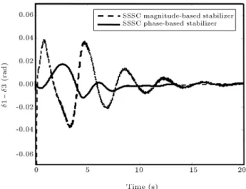
show that SSSC-based stabilizers can eectively damp inter-area oscillations. Typically, in case 3, the control signals of SSSC stabilizers are shown in Figure 14. It can be seen that the -based stabilizer provides much less control eort compared to the m-based stabilizers. Three-Area Six-Machine Power System
To conrm the obtained results on a 4-machine power system, in the following a 3-area 6-machine power sys-tem is investigated. A one-line diagram of the syssys-tem is shown in Figure 15. Data of the system are represented
Figure 12. Swing angle of G1 relative to G3 for case 2.
in [22]. For increasing the transmitted power from area 1 to other areas, the real power of generators 3 and 4 and the load at bus 11 are increased. Inter-area modes and local modes in the open-loop system at light and heavy loading are listed in Table 9. Under light loading and heavy loading conditions, transmitted power is considered P = 470 MW and 750 MW, respectively. Mode shapes show that inter-area mode 1 consists of the machines of area 1 oscillating against the machines of areas 2 and 3, and inter-area mode 2 consists of the machines of area 2 oscillating against the machines of area 3. Because the damping ratio of
inter-Table 9. Inter-area and local modes and their damping ratio in open-loop system. Mode Light Loading Heavy Loading Inter-area mode 1 0:127 j5:490 (2:32%) 0:046 j4:829 (0:952%) Inter-area mode 2 0:312 j7:273 (4:28%) 0:291 j7:295 (3:99%) Local mode 1 1:373 j12:358 (11:04%) 1:348 j12:378 (10:83%) Local mode 2 1:859 j11:450 (16:02%) 1:456 j11:886 (12:16%) Local mode 3 2:392 j11:256 (20:79%) 2:328 j11:289 (20:19%)
Figure 13. Swing angle of G1 relative to G3 for case 3.
Figure 14. Control signals of SSSC stabilizers for case 3 with fault duration of 0.05s.
area mode 1 is low, a SSSC is installed on tie-line 8-11 to improve the damping ratio of this mode. Also, the damping ratio of local mode 1 related to the machines of area 3, and local mode 2 related to the machines of area 1, is not sucient. Participation factors show that generator 2 and generator 4 are the best places for installing PSS to improve the damping of these local modes. Specic parameters used for SSSC are given in the Appendix.
Figure 15. One-line diagram of 6-machine power system.
It is supposed that the minimum desired damping ratio for inter-area mode 1 is = 15% and for local modes is = 20%. The time constant of the stabilizer for SSSC and PSS are set as T = 0:2 and 0.1s, respectively. Considering the variation of the line current as the input signal, the parameters of PSSs and SSSC stabilizers are shown in Tables 10 and 11. Closed-loop oscillation modes are shown in Tables 12 and 13.
Table 10. Parameters of PSS and SSSC -based stabilizer, 6-machine power system.
Operating
Condition Stabilizer x2 x1 x0 SSSC 0.0167 0.2067 0.0092 Light loading PSS2 0.0220 0.4078 1.8835 PSS4 0.0073 0.1000 0.2658 SSSC 0.0051 0.0135 0.0055 Heavy loading PSS2 0.0265 0.4437 1.7823 PSS4 0.0195 0.2686 0.7289
Table 11. Parameters of PSS and SSSC m-based stabilizer, 6-machine power system.
Operating
Condition Stabilizer x2 x1 x0 SSSC 0.0164 0.0904 0.0411 Light loading PSS2 0.0219 0.4379 2.1895 PSS4 0.0184 0.2303 0.4901 SSSC 0.0420 0.2255 0.1025 Heavy loading PSS2 0.0222 0.4194 1.9757 PSS4 0.0208 0.2876 0.8035
These tables show that in addition to the damping ratio of inter-area mode 1 the damping ratio of inter-area mode 2 is also signicantly improved.
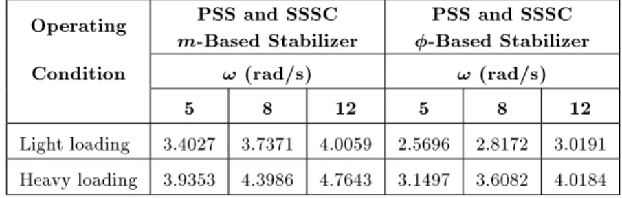
Norm-1 at dierent values of ! is shown in Table 14. Obtained results on a 6-machine power system like the obtained results on a 4-machine power system show that when the SSSC is installed on a tie-line that interconnects two areas in a multi-machine
power system and a SSSC stabilizer is included in the phase control channel, it is more eective for damping inter-area oscillations.
Although in the 6-machine power system the results are shown for certain values of transmitted power, the same conclusion can be obtained for other values of transmitted power.
To show the performance of designed stabilizers under heavy loading conditions, a three-phase fault is applied to Bus 9 with fault duration of 0.02 s. The swing angle of generator 3, with respect to generator 6 for a SSSC stabilizer in dierent control channels, is shown in Figure 16. This gure shows that inter-area mode 1 is damped eectively.
CONCLUSION
In this paper, a method for the simultaneous co-ordinated tuning of a SSSC-based stabilizer and a PSS in a multi-machine power system is presented by quadratic mathematic programming. In this method,
Table 12. Inter-area and local modes and their damping ratio in closed-loop system in the case of PSS and SSSC m-based stabilizer.
Mode Light Loading Heavy Loading Inter-area mode 1 0:920 j6:012 (15:12%) 0:781 j5:035 (15:32%) Inter-area mode 2 0:986 j7:382 (13:24%) 0:943 j7:397 (12:64%) Local mode 1 2:461 j11:998 (20:08%) 2:443 j11:980 (20:00%) Local mode 2 2:374 j11:339 (20:49%) 2:409 j11:462 (20:57%) Local mode 3 2:397 j11:250 (20:84%) 2:351 j11:297 (20:37%)
Table 13. Inter-area and local modes and their damping ratio in closed-loop system in the case of PSS and SSSC -based stabilizer.
Mode Light Loading Heavy Loading Inter-area mode 1 0:991 j6:288 (15:56%) 0:793 j5:047 (15:52%) Inter-area mode 2 1:307 j7:569 (17:01%) 0:958 j7:280 (13:04%) Local mode 1 2:530 j12:024 (20:59%) 2:390 j11:690 (20:03%) Local mode 2 2:409 j11:302 (20:85%) 2:359 j11:501 (20:09%) Local mode 3 2:711 j10:906 (24:12%) 2:366 j11:315 (20:47%)
Table 14. The values of norm-1 at dierent values of !, 6-machine power system. Operating PSS and SSSC
m-Based Stabilizer
PSS and SSSC -Based Stabilizer Condition ! (rad/s) ! (rad/s)
5 8 12 5 8 12 Light loading 3.4027 3.7371 4.0059 2.5696 2.8172 3.0191 Heavy loading 3.9353 4.3986 4.7643 3.1497 3.6082 4.0184
Figure 16. Swing angle of G3 relative to G6 for heavy loading.
the gain and phase of the stabilizer are calculated simultaneously. This method is not time-consuming and the parameters of stabilizers can be calculated by a few iterations. By this method, the inuence of a SSSC-based stabilizer in dierent control channels on damping inter-area oscillations has been investigated. Analytical expression for the comparison of eects of SSSC-based stabilizers in dierent control channels on damping inter-area oscillation, if not impossible, is very dicult. However, obtained results under dierent operating conditions on a 2-area and 3-area power system interconnected with a weak tie line show that a SSSC-based stabilizer in the phase control channel (-based stabilizer) is more eective for damping inter-area oscillation than a magnitude-based stabilizer (m-based stabilizer). In the case of a -(m-based stabilizer, to achieve the same desired value of damping ratio, control cost, i.e. the value of the stabilizer loop gain is lower than the m-based stabilizer. It seems that the results can be generalized to other multi-machine power systems interconnected with tie-lines, because an inter-area mode consists of machines in an inter-area oscillating against the machines of that or other areas, as the studied systems.
REFERENCES
1. Kazemi, A. and Karimi, E. \The eect of an interline power ow controller (IPFC) on damping inter-area oscillations in interconnected power systems", Scientia Iranica, 15(2), pp. 211-216 (2008).
2. Hessami Naghshbandi, A. et al. \An investigation on the performance of approximate methods in the repre-sentation of stressed power system", Scientia Iranica, Trans. D, Comp. Science and Elec. Eng., 16(1), pp. 74-83 (2009).
3. Noroozian, M. et al. \A robust control strategy for shunt and series reactive compensators to damp
elec-tromechanical oscillations", IEEE Trans. Power Del., 16(4), pp. 812-817 (2001).
4. Gyugyi, L. et al. \Static synchronous series compen-sator: a solid-state approach to the series compensa-tion of transmission lines", IEEE Trans. Power Del., 12(1), pp. 406-417 (1997).
5. Haque, M.H. \Damping improvement by FACTS de-vices: A comparison between STATCOM and SSSSC", J. of Elect. Power Syst. Res., 73, pp. 177-185 (2005). 6. Chen, J. et al. \Enhancement of power system
damp-ing usdamp-ing VSC-based series connected FACTS con-trollers", IEE Proc. - Gener. Transm. Distrib., 150(2), pp. 353-359 (2003).
7. Farsangi, M.M. et al. \Choice of FACTS devices control inputs for damping inter-area oscillations", IEEE Trans. PWRS, 19(2), pp. 1135-1142 (2005). 8. Castro, M.S. et al. \Impacts of FACTS controllers on
damping power systems low frequency electromechan-ical oscillations", IEEE-PES: Transm. Distrib. Conf. and Exp. (2004).
9. Wang, H.F. \Static synchronous series compensator to damp power system oscillation", J. of Elect. Power Syst. Res., 54(8), pp. 113-119 (1999).
10. Kazemi, A. et al. \Optimal selection of SSSC Based damping stabilizer parameters for improving power system dynamic stability using genetic algorithm", Iranian Journal of Science & Technology, Transaction B, Engineering, 29(B1), pp. 1-10 (2005).
11. Rigby, G.S. et al. \Analysis of a power oscillation damping scheme using a voltage-source inverter", IEEE Trans. Indust. Appl., 38(4), pp. 1105-1113 (2002).
12. Park, J.W. et al. \New external neuro-controller for series capacitive reactance compensator in a power network", IEEE Trans. PWRS, 19(3), pp. 1462-1472 (2004).
13. Jowder, F.A.L. and Ooi, B.T. \Series compensation of radial power system by a combination of SSSC and dielectric capacitors", IEEE Trans. PWRS, 20(1), pp. 458-465 (2005).
14. Pourbeik, P. and Gibbard, M.J. \Damping and syn-chronizing torques induced on generators by FACTS stabilizers in multi-machine power systems", IEEE Trans. PWRS, 11(4), pp. 1920-1925 (1996).
15. Pourbeik, P. and Gibbard, M.J. \Simultaneous co-ordination of power system stabilizers and FACTS device stabilizers in a multi-machine power system for enhancing dynamic performance", IEEE Trans. PWRS, 13(2), pp. 743-479 (1998).
16. Da Cruz, J.J. and Zanetta, J.J. \Stabilizer design for multi-machine power system using mathematical programming", Int. J. Elec. Power Energy. Syst., 19(8), pp. 519-523 (1997).
17. Zanetta, L.C. and Da Cruz, J.J. \An incremental approach to the coordinated tuning of power system stabilizers using mathematical programming", IEEE Trans. PWRS, 20(1), pp. 895-902 (2005).
18. Sauer, P. and Pai, M., Power System Dynamics and Stability, Prentice Hall, New Jersey (1998).
19. Anderson, P.M. and Fouad, A.A., Power System Con-trol and Stability, Iowa, Iowa State Univ. Press (1977). 20. Dorf, R.C. and Bishop, R.H., Modern Control Systems,
Prentice Hall (2005).
21. Liu, S. et al. \Assessing placement of controllers and nonlinear behavior using normal form analysis", IEEE Trans. PWRS, 20(3), pp. 1486-1495 (2005).
22. Taranto, G.N. et al. \Robust decentralized control design for damping power system oscillation", The 33rd IEEE Conf. on Decision and Control, Orlando, Florida, pp. 4080-4085 (1994).
APPENDIX
Specic parameters used for SSSC (all in p.u. except where indicated):
4-machine power system:
TS = 0:01 s; XSCT= 0:15; Cdc= 1;
Vdcref= 1; KP = 25; KI = 200:
6-machine power system:
TS = 0:01 s; XSCT= 0:15; Cdc= 1;
Vdcref= 1; KP = 26; KI = 100:
BIOGRAPHIES
Mahmoud Reza Shakarami was born in Khorram-abad, Iran, in 1972. In 2000, he received his M.S. degree in Electrical Engineering from Iran University of Science and Technology in Tehran, Iran, where he is currently a Ph.D. candidate. His current research interests are: Power System Dynamics and Stability and FACTS Devices.
Ahad Kazemi was born in Tehran, Iran, in 1952. He received his M.S. degree in Electrical Engineering from Oklahoma State University, USA, in 1979 and is currently an Associated Professor in Electrical Engi-neering Department of Iran University of Science and Technology, in Tehran, Iran. His research interests are: Reactive Power Control, Power System Dynamics and FACTS Devices.