ATI FireMV 2400/ATI FirePro 2450
User Guide
© 2008 Advanced Micro Devices Inc. All rights reserved.
The contents of this document are provided in connection with Advanced Micro Devices, Inc. (“AMD”) products. AMD makes no representations or warranties with respect to the accuracy or completeness of the contents of this publication and reserves the right to discontinue or make changes to products, specifications, product descriptions, and documentation at any time without notice. No license, whether express, implied, arising by estoppel or otherwise, to any intellectual property rights is granted by this publication. Except as set forth in AMD’s Standard Terms and Conditions of Sale, AMD assumes no liability whatsoever, and disclaims any express or implied warranty, relating to its products including, but not limited to, the implied warranty of merchantability, fitness for a particular purpose, or infringement of any intellectual property right. AMD’s products are not designed, intended, authorized or warranted for use as components in systems intended for surgical implant into the body, or in other applications intended to support or sustain life, or in any other application in which the failure of AMD’s product could create a situation where personal injury, death, or severe property or environmental damage may occur. Trademarks
AMD, and the AMD Arrow logo, and combinations thereof, ATI, the ATI logo, Avivo, Catalyst, Catalyst Control Center, CrossFireX, HyperMemory, PowerPlay, Radeon, SurroundView, The Ultimate Visual Experience and combinations thereof are trademarks of Advanced Micro Devices, Inc.
HyperTransport is a licensed trademark of the HyperTransport Technology Consortium.
Microsoft, Windows, and Vista are registered trademarks of the Microsoft Corporation in the United States and/or other jurisdictions.
Other names are for informational purposes only and may be trademarks of their respective owners. Dolby Laboratories, Inc.
Manufactured under license from Dolby Laboratories. Dolby and the double-D symbol are trademarks of Dolby Laboratories.
© 1992-1997 Dolby Laboratories, Inc. All rights reserved. Macrovision
Apparatus Claims of U.S. Patent Nos. 6,836,549; 6,381,747; 7,050,698; 6,516,132; and 5,583,936. Licensed for limited viewing uses only.
This product incorporates copyright protection technology that is protected by US patents and other intellectual property rights. Use of this copyright protection technology must be authorized by
Macrovision, and is intended for home and other limited viewing uses only unless otherwise authorized by Macrovision. Reverse engineering or disassembly is prohibited.
Disclaimer
While every precaution has been taken in the preparation of this document, Advanced Micro Devices, Inc. assumes no liability with respect to the operation or use of AMD hardware, software or other products and documentation described herein, for any act or omission of AMD concerning such products or this documentation, for any interruption of service, loss or interruption of business, loss of anticipatory profits, or for punitive, incidental or consequential damages in connection with the furnishing,
performance, or use of the AMD hardware, software, or other products and documentation provided herein. Ensure that you have the latest documentation.
Important Safety Instructions
Note: This product is for use only with compatible UL-listed personal computers that have installation instructions detailing user installation of this class of product.
Read all instructions before beginning installation. All safety and installation instructions should be read before the product is installed or operated.
Retain all instructions. Safety, installation, and operating instructions should be retained for future reference.
Heed all warnings. All warnings regarding the product and its operating instructions should be obeyed.
Use appropriate grounding. Caution:
For continued protection against the risk of electric shock and fire, install this accessory only in products equipped with a three-wire grounding plug, a plug having a third (grounding) pin. This is a safety feature. Do not remove the grounding pin of a three-pin plug.
Attach product securely. All product-securing screws or fasteners should be completely tightened in order to provide continuous bonding between the product and the PC chassis, as appropriate.
For cards with TV tuners:
• Ground outdoor antenna appropriately. Caution:
Since an outdoor antenna or cable system may be connected to the product, be sure that the antenna or cable system is grounded so as to provide some protection against voltage surges and built-up static charges. Article 810 of the National Electrical Code, ANSI/NFPA 70 and the Canadian Electrical Code, Section 54 provide useful information.
• Unplug system during storms or prolonged disuse.
Caution:
For added protection for this product during a lightning storm, or when it is left unattended and unused for long periods of time, unplug it from the wall outlet and disconnect the antenna or cable system. This will help prevent damage to the product from power-line surges.
• Install outdoor antenna system away from power lines.
Warning:
When installing an outside antenna system, extreme care should be taken to keep from touching such power lines or circuits, as contact with them may be fatal.
Caution:
An outside antenna system should not be located in the vicinity of overhead power lines or other light or power circuits, or where it can fall into such power lines or circuits.
iii
Note to CATV System Installer
This reminder is provided to call the CATV systems installer’s attention to Section 820-40 of the NEC, which provides guidelines for proper grounding and, in particular, specifies that the cable ground shall be connected to the grounding system of the building as close to the point of cable entry as is practical.
Contents
Getting Started . . . 1
System Requirements . . . 1
Performing a Quick Installation . . . 1
Before You Begin . . . 2
Graphics Card Bus Types . . . .2
Recording Serial Numbers . . . .3
Uninstalling Previous Drivers in Windows XP . . . .3
Uninstalling Previous Drivers in Windows Vista . . . .4
Hardware Installation . . . 5
Installing a Graphics Card . . . 5
Baseplate Connections . . . 6
VHDCI Cable . . . 6
Using Adapters . . . 8
Display Configurations . . . 9
Drivers and Software Installation . . . 11
ATI Drivers and Software . . . 11
Microsoft .NET Framework . . . .11
Linux Drivers . . . .11
Installing ATI Drivers and Software in Windows XP . . . 11
Installing ATI Drivers and Software in Windows Vista . . . 12
HydraVision Multi-monitor Software . . . 13
Basic Display Configuration . . . .15
Configuring a Display with ATI Catalyst Control Center . . . .15
Configuring a Display with Catalyst Control Panel . . . 16
ATI Catalyst Control Center . . . 17
ATI Catalyst Control Center Overview . . . 17
Starting the ATI Catalyst Control Center Software . . . 17
Accessing ATI Catalyst Control Center Help . . . .18
Catalyst Control Panel . . . 19
Accessing the Catalyst Control Panel . . . 19
ATI Displays . . . .20
Enabling or Disabling a Display . . . .21
Saving a Display-device Scheme . . . .22
Dynamic Display Reassignment . . . .22
ATI Color Tab . . . 22
ATI Color . . . .22
Creating a Desktop or Full Screen 3D Profile . . . .24
Applying the Settings for a Specific Desktop Profile . . . .25
Applying the Settings for a Full Screen 3D Profile . . . .25
Hotkeys . . . .25
ATI OpenGL Tab . . . .27
ATI OpenGL . . . . 27
ATI Direct3D Tab . . . 29
ATI Direct3D . . . .29
ATI Options Tab . . . 32
ATI Options . . . .32
ATI Rotation Tab . . . .34
ATI Rotation . . . .34
Rotating a Display . . . .36
Hotkeys . . . .36
ATI Overlay Tab . . . 36
ATI Overlay . . . .36
Reference . . . .39
Workstation Card Troubleshooting . . . .39
Computer does not boot up properly. . . .39
There is no display. . . .39
There are screen defects. . . .40
The screen image is off-center or there are odd colors. . . . .40
The operating system warns that the graphics card isn't properly configured. . . . 40
Stereo glasses are not working properly. . . .40
There are bus address or interrupt conflicts. . . .40
Workstation Customer Care . . . 41
Web . . . .41
E-mail . . . .41
Telephone . . . .42
Surface Mail . . . .43
Disclaimer . . . . 43
Workstation Warranty Service . . . 44
Shipping . . . .44
Limitations . . . .44
Additional Accessories . . . 45
International Compliance Information . . . 45
FCC Compliance Information . . . .45
Industry Canada Compliance Statement . . . .46
CE Compliance Information . . . .46
Electrical Safety . . . .46
Waste Electrical and Electronic Equipment (WEEE) Directive Compliance . . . .47
VCCI Class B ITE Compliance Information . . . .47
MIC Certification Information . . . .47
BSMI Certification Information . . . .48
Glossary - Workstation Products . . . 49
viiChapter 1
Getting Started
Before you begin installing your new ATI FireMV 2400/ATI FirePro 2450 graphics accelerator, please make sure you have the proper system requirements and have completed the required preinstallation tasks as outlined in this chapter.System Requirements
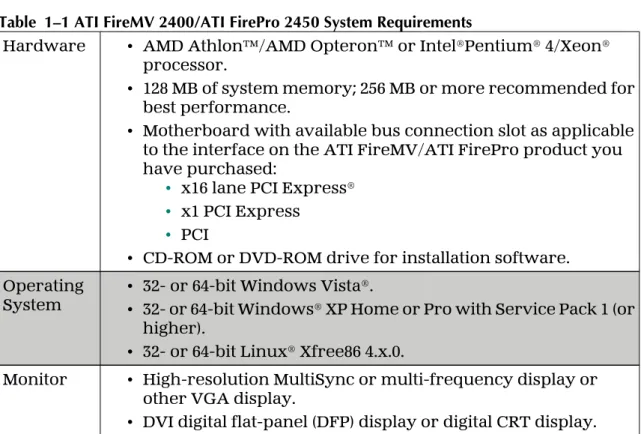
Table 1–1 ATI FireMV 2400/ATI FirePro 2450 System Requirements
Hardware • AMD Athlon™/AMD Opteron™ or Intel®Pentium® 4/Xeon® processor.
• 128 MB of system memory; 256 MB or more recommended for best performance.
• Motherboard with available bus connection slot as applicable to the interface on the ATI FireMV/ATI FirePro product you have purchased:
• x16 lane PCI Express® • x1 PCI Express
• PCI
• CD-ROM or DVD-ROM drive for installation software. Operating
System •• 32- or 64-bit Windows Vista®.32- or 64-bit Windows® XP Home or Pro with Service Pack 1 (or higher).
• 32- or 64-bit Linux® Xfree86 4.x.0.
Monitor • High-resolution MultiSync or multi-frequency display or other VGA display.
• DVI digital flat-panel (DFP) display or digital CRT display.
Performing a Quick Installation
Experienced users and system administrators can follow these brief instructions for installing this ATI FireMV/ATI FirePro product.
Other users should refer to the detailed installation instructions, starting with Hardware Installation on page 5.
1.
Uninstall the drivers and software for any installed graphics card(s).Note: If you are using a motherboard containing an on-board graphics solution and do not intend to use it as part of a multiple monitor display, disable it.
2.
Shut down and disconnect your computer system.3.
Remove any installed graphics card(s).4.
Install your new ATI FireMV/ATI FirePro graphics card.5.
Reassemble and connect your computer system.6.
Install the ATI FireMV/ATI FirePro drivers and configuration software from the ATI Installation disc.Before You Begin
Before you begin installing your new ATI FireMV 2400/ATI FirePro 2450 graphics card, please perform the following tasks.
Graphics Card Bus Types
Your graphics card connects to the motherboard through a bus slot, the most common types of which are shown in the following figure:
Figure 1–1 Common Graphics Card Bus Types
1 AGP card connector and motherboard slot 2 PCI card connector and motherboard slot
3 PCI Express (PCIe®) x16 card connector and motherboard slot 4 PCIe x1 card connector and motherboard slot
Make sure you have an available bus slot on your motherboard for the type of ATI FireMV/ATI FirePro graphics card you have purchased before beginning your installation.
Recording Serial Numbers
The serial number and 102 part number on the graphics card are required for product registration. They are located on a white sticker on the back of the graphics card and are shown in boldface and underlined in the illustration below. Record these numbers in the space provided below and retain for future use.
1.
Remove the graphics card from packing.2.
Locate the white label on the back of the graphics card.3.
Record the serial number and 102 part number.Figure 1–2 Typical Serial Number and 102 Part Number Arrangement
1 Serial number (S/N) 2 102 part number (P/N)
Uninstalling Previous Drivers in Windows XP
Follow these steps to uninstall the existing graphics card driver in Windows XP in preparation for installation of a new card.
1.
With the current graphics card still in the computer, close all open applications.2.
On the Windows taskbar, click Start ▷ Control Panel and then double-clickAdd or Remove Programs.
3.
Select the current graphics card driver and then click Add/Remove.The wizard will appear and help remove the current display drivers.
4.
Turn off the system after the driver has been removed.Note: If the previously installed graphics card has any additional software installed, this software may also need to be removed before restarting the computer. For example, DVD Player or Multimedia applications.
Recording Serial Numbers 3
Uninstalling Previous Drivers in Windows Vista
Follow these steps to uninstall the existing graphics card driver in Windows Vista in preparation for installation of a new card.
1.
With the current graphics card still in the computer, close all open applications.2.
Click Start ▷ Control Panel. Double-click Programs and Features and then select the graphics card driver from the list of software programs.3.
Double-click Hardware and Sound and then double-click Device Manager.4.
Expand Display Adapter and then right-click the driver for the graphics cardyou are replacing.
5.
In the shortcut menu that appears, click Install.The driver for the old graphics card is uninstalled.
6.
Turn off the system.Chapter 2
Hardware Installation
This chapter details how to install the ATI FireMV/ATI FirePro graphics card into your computer.Installing a Graphics Card
Make sure you have completed the preinstallation steps outlined in Getting Started on page 1.
Please read all installation instructions completely before you begin.
1.
Turn off your computer, monitor(s), and other peripheral devices.2.
Unplug the computer's power cord and disconnect all cables from the back of the computer.Caution:
Wait approximately 20 seconds after unplugging the power cord before disconnecting a peripheral or removing a component from the
motherboard to avoid possible damage to the motherboard.
3.
Remove the cover to your computer's case.Note: If necessary, consult your computer's manual for help in removing the cover.
Caution:
Static electricity can seriously damage computer components. Discharge your body's static electricity by touching the power supply or the metal surface of the computer chassis before you touch any components inside your computer's case to avoid damaging them.
4.
Unscrew or unfasten and remove any existing graphics card from your computer.Note: If the computer has an on-board graphics capability, you may need to disable it on the motherboard. For more information, see your motherboard documentation.
5.
Locate the appropriate slot and, if necessary, remove the metal back-plate cover. Make sure all internal cables are clear of the slot.6.
Align your ATI FireMV/ATI FirePro graphics card with the slot and press it in firmly until the card is fully seated. You may need to hold open a locking tab on the slot with your finger when you seat the card.7.
Screw in or fasten the graphics card securely.8.
Make sure no internal cables are interfering with anything inside the computer (for example, a cooling fan) and replace the computer cover.9.
Reconnect any cables that were disconnected during installation and plug in the computer's power cord.10.
Turn on the monitor, and then your computer.If you have properly installed your graphics card, operating system messages will appear and the boot procedure will proceed.
Your monitor will be running in a basic (VGA) video mode. Higher refresh rates are not available at this stage of the installation. Once you have installed the ATI FireMV/ATI FirePro drivers and software, you can use
ATI Catalyst™ Control Center to adjust your video settings and configure multiple monitors.
Proceed to install the software and drivers for your ATI FireMV/ATI FirePro graphics card.
Baseplate Connections
The following figures show the display connections available on your graphics card.
Note: Baseplates may not appear exactly as depicted.
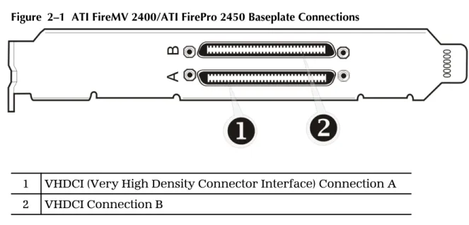
Figure 2–1 ATI FireMV 2400/ATI FirePro 2450 Baseplate Connections
1 VHDCI (Very High Density Connector Interface) Connection A 2 VHDCI Connection B
VHDCI Cable
Your ATI FireMV 2400/ATI FirePro 2450 card is designed for use with a pair of VHDCI (Very High Density Connector Interface) cables, each of which provides support for two monitors. The type of monitors supported depends on the cable or adapters used.
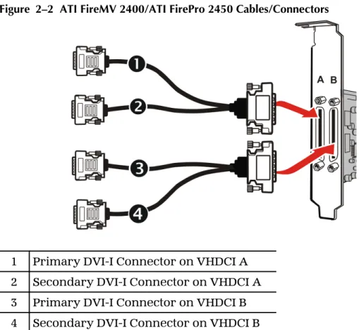
Figure 2–2 ATI FireMV 2400/ATI FirePro 2450 Cables/Connectors
1 Primary DVI-I Connector on VHDCI A 2 Secondary DVI-I Connector on VHDCI A 3 Primary DVI-I Connector on VHDCI B 4 Secondary DVI-I Connector on VHDCI B
Note: Each VHDCI cable has two connections: a primary and a secondary. If you are using a single display, make sure you connect it to the primary connection. A single display will not function properly if it is connected to the secondary connection.
A VHDCI cable's DVI connectors can be attached to VGA monitors using a VGA-to-DVI adapter.
7
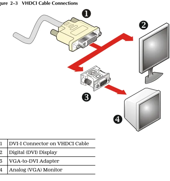
Figure 2–3 VHDCI Cable Connections
1 DVI-I Connector on VHDCI Cable 2 Digital (DVI) Display
3 VGA-to-DVI Adapter 4 Analog (VGA) Monitor
Note: For instructions on attaching adapters, please refer to Using Adapters on page 8.
Using Adapters
Your ATI FireMV/ATI FirePro graphics card includes adapters to enable you to attach display types other than those included on the baseplate or cables. Use the following procedure to attach a display using an adapter.
1.
Turn off your computer and monitor.2.
Plug the adapter into the connection from your ATI FireMV/ATI FirePro graphics card and tighten the thumbscrews (if there are any).3.
Connect your display's cable to the adapter and tighten the thumbscrews (if there are any).4.
Turn on your monitor first, then your computer.Use the ATI Catalyst Control Center to configure the new monitor.
Display Configurations
Your ATI FireMV 2400/ATI FirePro 2450 graphics card provides quad-display functionality through four DVI connections on two VHDCI cables.
Note: Up to 10 monitors may be supported using multiple graphics cards; for more information, consult the ATI Catalyst Control Center online help. The following table lists the different ways you can connect displays to your card:
Display Configuration Connector(s) Used
DFP (digital flat-panel) display DVI connector
VGA display VGA connector with VGA-to-DVI adapter
9
Chapter 3
Drivers and Software Installation
This chapter describes the installation of the drivers and software associated with your ATI FireMV/ATI FirePro graphics card.ATI Drivers and Software
Drivers are small but important programs that enable an operating system to communicate with a piece of hardware, such as a graphics card.
When you install a new graphics card, you must also install the driver and configuration software the card requires to function properly.
You also need to install (or reinstall) your ATI FireMV/ATI FirePro drivers when you have reinstalled or upgraded your operating system or when you install updated drivers from ATI's Web site.
Note: When reinstalling drivers, always uninstall any previous drivers that are on your system, even if they are for the same graphics card. Always start "fresh."
Microsoft .NET Framework
ATI Catalyst Control Center requires Microsoft .NET Framework 2.0 to function. If you install your ATI software using a product's installation CD, Microsoft .NET Framework 2.0 will be installed automatically. If you download and install ATI software from the Internet, however, Microsoft .NET Framework 2.0 will not be installed. If it is not already on your system, you must download and install Microsoft .NET Framework 2.0 from Microsoft's Web site before you install ATI Catalyst Control Center.
You can check to see if Microsoft .NET Framework 2.0 is installed on your system by looking for it in the Add and Remove Programs dialog.
Linux Drivers
Linux drivers are not included on the installation CD-ROM. Linux drivers and software are available from the ATI Web site at ati.amd.com/support.
Installing ATI Drivers and Software in Windows XP
In order to install the drivers and software necessary for your ATI FireMV 2400/ ATI FirePro 2450 graphics card to function properly, the following must be true:• Your graphics card must be physically installed in your computer.
• Your operating system must be installed and operational; you must have at least Windows XP Service Pack 1 installed.
• You must log in as a user with administrator rights.
1.
Turn on your monitor and then turn on your computer. Wait for your operating system to boot up. When the Found New Hardware dialogappears, click Cancel. If the System Settings Change dialog asks if you want to restart your computer, click No.
2.
Run the Setup utility. The Setup utility may start automatically if you insert the ATI Installation CD-ROM into your CD-ROM or DVD-ROM drive after the operating system has started. If your CD-ROM auto-run feature is not enabled or the Setup utility is not on a CD-ROM (because it was downloaded from the Internet, for example):a.
In the Windows task bar, click Start.The Start Menu opens.
b.
Click Run.The Run dialog appears.
c.
Select Browse and select atisetup.exe from the root directory of the ATI Installation CD-ROM or the folder in which you have placed the driver.atisetup.exe appears in the Open field of the Run dialog.
d.
Click OK.3.
In the Software Install dialog, click Install.4.
Click Next.5.
Click Yes to the license agreement.ATI Easy Install will start the Installation Wizard.
6.
Follow the wizard’s on-screen instructions to complete the installation:➭
Select Express to install typical drivers and software.➭
Select Custom to choose individual software components for installation.Note: The Custom installation option is recommended for advanced users only.
7.
When the setup complete message appears, select Yes, I want to restart my computer now and click Finish.Your computer will reboot.
8.
After the system reboots, the Found New Hardware dialog may display theDigital Signature Not Found message. Click Yes or Continue to complete the driver installation.
Proceed to configure your video settings and connect additional monitors, if necessary.
Installing ATI Drivers and Software in Windows Vista
In order to install the drivers and software necessary for your ATI FireMV 2400/ ATI FirePro 2450 graphics card to function properly, the following must be true:• Your graphics card must be physically installed in your computer. • Your operating system must be installed and operational.
• You must log in as a user with administrator rights.
1.
Turn on your monitor and then turn on your computer. Wait for your operating system to boot up. You may receive a warning that the graphics driver failed to install. Close this dialog.2.
Run the Setup utility. The Setup utility may start automatically if you insert the ATI Installation CD-ROM into your CD-ROM or DVD-ROM drive after the operating system has started. If your CD-ROM auto-run feature is not enabled or the Setup utility is not on a CD-ROM (because it was downloaded from the Internet, for example):a.
In the task bar, click the Start (Windows icon) button.The Start Menu opens.
b.
Select All Programs ▷ Accessories ▷ Run.The Run dialog appears.
c.
Select Browse and select setup.exe from the root directory of the ATI Installation CD-ROM or the folder in which you have saved the driver download.setup.exe appears in the Open field of the Run dialog.
d.
Click OK.Note: The User Account Control dialog may appear; if so, click
Continue. The ATI Catalyst Install Manager dialog may prompt you to close all open applications; if so, do so.
3.
In the Software Install dialog, click Install.4.
Click Next.ATI Easy Install will start the Installation Wizard.
5.
Follow the wizard’s on-screen instructions to complete the installation:➭
Select Express to install typical drivers and software.➭
Select Custom to choose individual software components for installation.Note: The Custom installation option is recommended for advanced users only.
6.
Click Yes to the license agreement.7.
When installation is complete, select View Log to review installation details. Click Finish when are done; you will be prompted to reboot your computer.Your computer will reboot.
Proceed to configure your video settings and connect additional monitors, if necessary.
HydraVision Multi-monitor Software
The HydraVision™ multi-monitor and desktop management software will install automatically with an Express installation of the ATISETUP utility.
Note: If you do not want to install HydraVision, select the Custom driver installation and clear the HydraVision check box.
Linux Drivers 13
For more information, consult the HydraVision User's Guide or the online help available through the ATI Catalyst Control Center.
Chapter 4
Basic Display Configuration
This chapter contains basic procedures for configuring your displays.Configuring a Display with ATI Catalyst Control Center
A monitor must be connected to your computer to be configured.Use the following procedure to configure a display in ATI Catalyst Control Center's Advanced view.
Note: A simplified version of this procedure is available through the ATI Catalyst Control Center Basic view using the Setup my display configuration option on the Easy Setup Wizards Tab.
1.
Open ATI Catalyst Control Center in the Advanced view.Note: For more information, see Starting the ATI Catalyst Control Center Software on page 17.
2.
Select the Displays Manager aspect.3.
To select a primary monitor, right-click the numbered monitor icon you wish and choose Primary.4.
To enable a monitor that is connected but disabled, right-click the numbered monitor icon you wish and choose Enable5.
To configure the display properties of a monitor, left-click the numbered monitor icon you wish to configure (if it is not already selected) and select values for the Desktop Area (resolution), Color Quality, and Refresh Ratefrom the drop-down menus that best suit your requirements and your monitor’s performance.
Caution:
Choosing a refresh rate that your monitor does not support may damage your monitor. Consult your monitor's documentation, if necessary.
6.
To extend your Windows desktop from a primary onto a secondary display, right-click on the icon in the Desktop 2 area and choose the appropriate option.➭
Choose Clone desktop... to mirror the display on Desktop 1.➭
Choose Stretch desktop... to extend the display across both desktops (horizontally or vertically).7.
Click Apply to apply your selections or OK to apply your selections and close ATI Catalyst Control Center.Configuring a Display with Catalyst Control Panel
Before configuring a secondary display, make sure you have configured your primary display. Your monitor must be connected to your computer to be configured.Note: When you use multiple monitors with your card, one monitor will always be designated Primary; additional monitors will be designated Secondary.
Use the following procedure to configure a display with Control Panel.
1.
In Windows:➭
Navigate to the Control Panel and choose Display, or➭
Right-click on the desktop and choose Properties.The Display Properties dialog appears.
2.
Click the Settings tab to access the basic multi-monitor configuration settings.Note: ATI software provides many additional configuration features.
3.
Select the monitor icon identified by the appropriate number (for example, 1for the primary display, 2 for a secondary display).
4.
When configuring a secondary display, select the Extend my Windows desktop onto this monitor option to enable the Windows desktop to "stretch" across the primary and secondary monitor(s).5.
Select values for the Screen Resolution and Color Quality that best suit your requirements and your monitor’s performance.6.
Click Advanced.The Advanced Display Properties dialog appears.
7.
Choose a refresh rate from the Screen Refresh Rate drop-down menu in the Monitor Settings section.Caution:
Choosing a refresh rate that your monitor does not support may damage your monitor. Consult your monitor's documentation, if necessary.
8.
Click OK to close the Advanced Display Properties dialog, and then click OKto close the Display Properties dialog.
Note: Refer to Windows help and documentation for further information on using the Display Properties dialog.
Chapter 5
ATI Catalyst Control Center
This chapter introduces the ATI Catalyst Control Center, a graphical userapplication that provides access to the display features of the graphics card.
ATI Catalyst Control Center Overview
The ATI Catalyst Control Center software provides access to the display features of the graphics card. Use the software to fine-tune graphics settings, enable or disable connected display devices, and change the orientation of the desktop. Many features display previews of the changes before they are applied. The following configurations are available:
Basic View A simplified view of the features that includes wizards to quickly make changes.
Advanced View
A powerful interface that enables complete configuration of the feature set of the graphics card.
Custom View A customized view so that desired features can be accessed quickly.
For information on the individual features of the software, access the
comprehensive in-program help system (see Accessing ATI Catalyst Control Center Help on page 18 or visit the AMD Customer Care Web site at ati.amd.com/ support/).
Starting the ATI Catalyst Control Center Software
The following table shows the ways you can start the ATI Catalyst Control Center software:
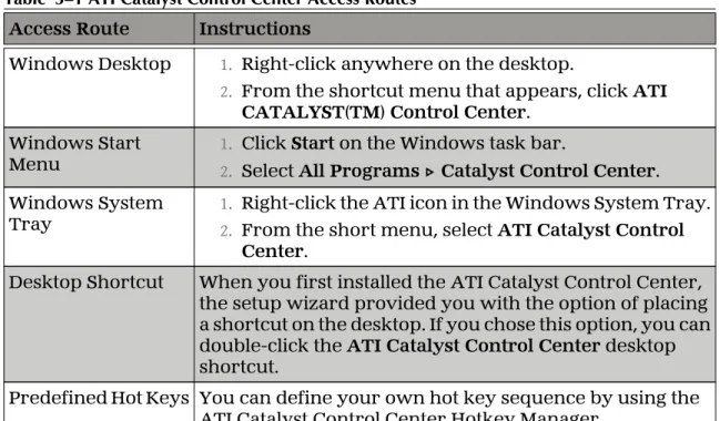
Table 5–1 ATI Catalyst Control Center Access Routes
Access Route Instructions
Windows Desktop 1. Right-click anywhere on the desktop.
2. From the shortcut menu that appears, click ATI CATALYST(TM) Control Center.
Windows Start
Menu 1.2. Click Select StartAll Programs on the Windows task bar.▷ Catalyst Control Center. Windows System
Tray 1.2. Right-click the ATI icon in the Windows System Tray.From the short menu, select ATI Catalyst Control
Center.
Desktop Shortcut When you first installed the ATI Catalyst Control Center, the setup wizard provided you with the option of placing a shortcut on the desktop. If you chose this option, you can double-click the ATI Catalyst Control Center desktop shortcut.
Predefined Hot Keys You can define your own hot key sequence by using the ATI Catalyst Control Center Hotkey Manager.
Accessing ATI Catalyst Control Center Help
ATI Catalyst Control Center Help provides information on the features and concepts of your ATI FireMV/ATI FirePro graphics card. You can also use the ATI Catalyst Control Center Help feature to access usage information, generate a problem report, and get software version information for your graphics card.
1.
Open ATI Catalyst Control Center in the Advanced view.2.
Choose one of the following options:➭
Press the F1 key at any time to get specific help on the currently displayed information.➭
From the ATI Catalyst Control Center Dashboard, choose Help ▷ Help Contents to browse the entire help contents.➭
From the ATI Catalyst Control Center Dashboard, choose Help ▷ Search Help to search the help contents for a specific term.➭
To access AMD's Web site, from the ATI Catalyst Control Center Dashboard, choose Help ▷ Go to ATI.com.Chapter 6
Catalyst Control Panel
This topic describes the software associated with the ATI FireMV/ATI FirePro graphics card when you are using the Control Panel. For information on using ATI Catalyst Control Center, please refer to ATI Catalyst Control Center on page 17Accessing the Catalyst Control Panel
The Catalyst Software Suite installs the ATI display tabs into the Windows Display Properties dialog. These tabs are accessed through the Advanced button located on the Settings tab.
To access the Display Properties dialog, right-click on the desktop or navigate through the Windows Control Panel, which is located in the Start menu. Figure 6–1 Windows Display Properties Settings Tab
ATI Displays Tab
The ATI Displays tab provides settings to enable specific display (or multiple display) features.
ATI Displays
The ATI Displays tab provides control over multi-monitor features. Here you can enable/disable display devices and swap the assignment of Primary and
Secondary displays.
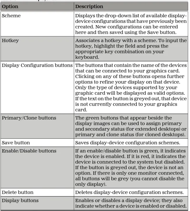
Table 6–1 ATI Displays Tab
Option Description
Scheme Displays the drop-down list of available display-device configurations that have previously been created. New configurations can be entered here and then saved using the Save button. Hotkey Associates a hotkey with a scheme. To input the
hotkey, highlight the field and press the appropriate key combination on your keyboard.
Display Configuration buttons The buttons that contain the name of the devices that can be connected to your graphics card. Clicking on any of these buttons opens further options to refine your display on that device. Only the type of devices supported by your graphic card will be displayed as valid options. If the text on the button is greyed out, that device is not currently connected to your graphics card.
Primary/Clone buttons The green buttons that appear beside the display images can be used to assign primary and secondary status (for extended desktops) or primary and clone status (for cloned desktops). Save button Saves display-device configuration schemes. Enable/Disable buttons If an enable/disable button is green, it indicates
the device is enabled. If it is red, it indicates the device is connected to the system but disabled. If the button is greyed out, the device is not an option. If there is only one monitor connected, all buttons will be grey (you cannot disable the only display).
Delete button Deletes display-device configuration schemes. Display buttons Enables or disables a display device; they also
indicate whether a device is enabled or disabled.
Enabling or Disabling a Display
If an enable/disable button is green, it indicates the device is enabled. If it is red, it indicates the device is connected to the system but disabled. If the button is greyed out, the device is not an option. If there is only one monitor connected, all buttons will be grey (you cannot disable the only display).
1.
Click the enable/disable button for the display device you want to enable/ disable.2.
Click OK or Apply to save the changes.Enabling or Disabling a Display 21
Saving a Display-device Scheme
Display-device selections can be saved as a scheme for quick recall.
1.
Click the enable/disable button for the display devices you want to have active.2.
Type a name into the Scheme drop-down list field.3.
Click Save to save the scheme.Dynamic Display Reassignment
You can change the assignment of your Primary and Secondary display without rebooting. If you have more than one display device available and have the proper adapters or connectors, you can plug it in to your graphics card in order to view or extend your desktop display to that device.
Note: Before you can change the assignment of the Primary display, at least one Secondary display and the Extended Desktop mode must be enabled. Extended Desktop mode is enabled through the Windows Display Property dialog, under Settings. For more information, consult your Windows documentation.
ATI Color Tab
The Color Tab provides access to fine color settings and preset color schemes.
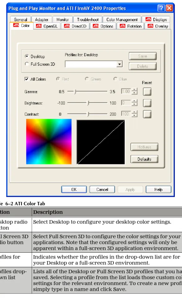
ATI Color
The ATI Color tab allows you to configure gamma, brightness, and contrast color settings for both your desktop and full screen 3D environments. You can also save settings to a color profile for easy recall. In addition, you can assign unique hotkey combinations that allow you to adjust gamma, brightness, and contrast color settings within your full-screen 3D applications.
Table 6–2 ATI Color Tab
Option Description
Desktop radio
button Select Desktop to configure your desktop color settings. Full Screen 3D
radio button Select Full Screen 3D to configure the color settings for your 3Dapplications. Note that the configured settings will only be apparent within a full-screen 3D application environment. Profiles for Indicates whether the profiles in the drop-down list are for
your Desktop or a full-screen 3D environment. Profiles
drop-down list Lists all of the Desktop or Full Screen 3D profiles that you havesaved. Selecting a profile from the list loads those custom color settings for the relevant environment. To create a new profile, simply type in a name and click Save.
ATI Color 23
Option Description
Save button Saves your current color settings to a Desktop or Full Screen 3D profile, using the name you specified in the Profiles list box. To restore these settings later, simply select the Profile name from the list and click Apply or OK.
Delete button Deletes the profile that is selected in the Profiles list box. All Colors
check box Adjusts the gamma, brightness or contrast for red, green, andblue simultaneously. Note that any individual color settings in effect are lost if All Colors is selected; the color settings revert back to the last-known All Colors settings.
Red, Green, and Blue radio buttons
Selects the active color component (red, green, or blue) whose values will be adjusted by the gamma, brightness, and contrast sliders. Note that any individual color settings made are lost if you subsequently select All Colors.
Gamma slider Increases or decreases the gamma correction of your desktop or full-screen 3D application. Changing the gamma alters the curvature of the color curve.
Brightness
slider Increases or decreases the color brightness of your desktop orfull-screen 3D application. Changing the brightness adjusts the vertical position of the color curve.
Contrast slide Increases or decreases the color contrast of your desktop or full-screen 3D application. Changing the contrast adjusts the slope of the color curve.
Reset buttons Restores an individual slider setting to its default value. Click
Apply or OK to save. Color preview
box The color image indicates visually how the Gamma, Brightnessand Contrast sliders affect the final color settings of your display device. In Desktop mode, clicking on this with your mouse pointer will change the image.
Hotkeys button Opens the Color Hotkeys Settings dialog. There you can assign hotkeys for adjusting your color settings within a full-screen 3D application environment. To activate this button, you must select the Full Screen 3D radio button.
Defaults button Restores all of the default color settings. Color Curve
box Graphically depicts changes to the color settings.
Creating a Desktop or Full Screen 3D Profile
1.
Choose either the Desktop or Full Screen 3D radio button, as desired.2.
Adjust the Gamma, Brightness, and Contrast sliders to the desired settings,either individually or using the All Colors check box.
3.
Type a profile name in the Profiles list box.4.
Click Save.Applying the Settings for a Specific Desktop Profile
1.
Choose the Desktop radio button.2.
Select the profile name from the drop-down list box.3.
Click Apply or OK.Applying the Settings for a Full Screen 3D Profile
1.
Choose the Full Screen 3D radio button.2.
Select the profile name from the drop-down list box.3.
Click Apply or OK.Hotkeys
Color Hotkeys
Some 3D applications automatically load their own color settings rather than those set through the ATI Color tab. To use custom settings, you can preconfigure hotkey combinations to either adjust the individual color properties or apply profiles you have created, once the 3D application is running.
Applying the Settings for a Specific Desktop Profile 25
Note: If you do not plan to use hotkeys, select the Disable hotkeys check box so as to not accidentally activate them.
Accessing the Color Hotkeys Settings Dialog
For the steps used to assign hot keys, refer to Assigning Color Hotkeys on page 26.
The easiest way to apply your own color settings from within a full screen 3D application is to:
1. Create a Full Screen 3D profile and save it.
2. Assign hotkeys for the “Load Current Profile” action through the Color Hotkeys Settings dialog.
3. Make sure that the profile you prefer is selected from the drop-down list box, and click OK.
4. Once inside the 3D application, use the hotkeys to trigger the profile. Some 3D applications allow you to switch easily between full-screen mode and windowed mode and do not load their own color settings. In windowed mode, you can make slider adjustments or select a different profile on the Color tab, then switch back to full-screen mode to see the effects immediately.
1.
Select the Full Screen 3D radio button.2.
Click the Hotkeys button to access the Color Hotkeys Settings dialog.Assigning Color Hotkeys
When assigning hotkeys, be careful that the key combinations you choose do not conflict with those of other applications in which you might want to use them. The Color Hotkeys Settings dialog only checks for duplications within the Color tab itself, insofar as it allows a hotkey combination to be assigned only once.
Note: If you do not plan to use hotkeys, select the Disable hotkeys check box so as to not accidentally activate them.
1.
In the Color Hotkeys Settings dialog, select a modifier key from the Modifier Key list.2.
Select a hotkey from the Hotkey list.3.
Select the action you want from the Hotkey Action list.4.
Click Add to create the hotkey combination.Note: Only one hotkey combination can be assigned to each action; if you assign a new combination for an action, it will overwrite an existing one.
This combination will appear in the Assigned Hotkeys text box.
Removing Color Hotkey Assignments
1.
In the Color Hotkeys Settings dialog, select a hotkey combination from theAssigned Hotkey text box.
2.
Click Remove.Note: Only one hotkey combination can be assigned to each action; if you assign a new combination for an action, it will overwrite an existing one automatically.
ATI OpenGL Tab
The OpenGL tab provides access to OpenGL® settings.
ATI OpenGL
The ATI OpenGL tab allows you to configure 3D OpenGL settings, including anti-aliasing and anisotropic filtering.
ATI OpenGL 27
Table 6–3 ATI OpenGL Tab
Option Description
Performance/Quality slider Controls the overall performance/image quality of your graphic application. Moving the slider to the left will maximize application performance, while moving the slider to the right will maximize image quality.
Custom Settings check box When Custom Settings is selected, the
Performance/Quality slider is disabled and custom settings are enabled. Using custom settings is recommended for advanced users only. SmoothVision™
Anti-aliasing SmoothVision (Anti-aliasing) improves imagequality by removing jagged edges from 3D images, resulting in smoother, more natural-looking objects. Anti-aliasing can be applied using different sample patterns and sample points, such as 2× or 4×. Moving this slider to the right increases sampling to provide the most realistic 3D image. Select the Application Preference check box to allow 3D applications to choose the level of anti-aliasing.
Clear the Application Preference check box to customize the anti-aliasing level.
SmoothVision Anisotropic
Filtering Anisotropic filtering uses a texture filteringtechnique that blends multiple texture samples together. The number of samples taken when anisotropic filtering is performed can vary. By moving this slider to the right, as the number of samples taken increases, the quality of the final image increases significantly. 16× provides
extremely detailed, crisp-looking images as a result of the largest number of texture samples possible. Selecting the Application Preference check box will result in high-quality images, with a negligible reduction in the application’s performance.
Select the Application Preference check box to allow 3D applications to choose the level of anisotropic filtering.
Clear the Application Preference check box to customize the anisotropic filtering level.
Texture Preference slider Choose between quality and performance textures for your applications. Moving the slider to the right delivers the highest quality experience. Moving the slider to the left emphasizes a high-performance solution while still providing good visuals.
Option Description
Mipmap Detail Level slider Choose the texture quality of the mipmaps the application will use. Moving the slider to the right selects a higher quality base mipmap, delivering the highest quality application experience. Moving the slider to the left selects a lower quality mipmap, delivering the highest application performance. Wait for Vertical Sync slider Controls whether the vertical sync is always on,
always off, or controlled by the application. Compatibility Settings
button Opens the OpenGL Compatability Settings dialog,where users can adjust the Z-buffer depth and triple buffering options.
Use the Force Z-buffer depth radio buttons to select a Z-buffer depth of 24 or 16 bits, or disable this option.
Use the Triple Buffering radio buttons to enable or disable this option.
Click the Defaults button to return to the default settings.
Defaults button Click the Defaults button to return to the default settings.
ATI Direct3D Tab
The Direct3D tab provides access to Direct 3D® settings.
ATI Direct3D
The ATI Direct3D tab allows you to configure Direct 3D settings, including anti-aliasing and anisotropic filtering.
ATI Direct3D 29
Table 6–4 ATI Direct3D Tab
Option Description
Performance/Quality
slider Controls the overall performance/image quality ofyour graphic application. Moving the slider to the left will maximize application performance, while moving the slider to the right will maximize image quality.
Custom Settings check box When Custom Settings is selected, the
Performance/Quality slider is disabled and custom settings are enabled. Using custom settings is recommended for advanced users only. SmoothVision Anti-aliasing SmoothVision (Anti-aliasing) improves image
quality by removing jagged edges from 3D images, resulting in smoother, more natural-looking objects. Anti-aliasing can be applied using different sample patterns and sample points, such as 2X or 4X. Moving this slider to the right increases sampling to provide the most realistic 3D image. Select the Application Preference check box to allow 3D applications to choose the level of anti-aliasing.
Deselect the Application Preference check box to customize the anti-aliasing.
SmoothVision Anisotropic
Filtering Anisotropic filtering uses a texture filteringtechnique that blends multiple texture samples together. The number of samples taken when anisotropic filtering is performed can vary. By moving this slider to the right, as the number of samples taken increases, the quality of the final image increases significantly. 16× provides
extremely detailed, crisp-looking images as a result of the largest number of texture samples possible. Selecting the Application Preference check box will result in high-quality images, with a negligible reduction in the application’s performance.
Select the Application Preference check box to allow 3D applications to choose the level of anisotropic filtering.
Clear the Application Preference check box to customize the anisotropic filtering level.
Texture Preference slider Choose between quality and performance textures for your applications. Moving the slider to the right delivers the highest quality experience. Moving the slider to the left emphasizes a high-performance solution while still providing good visuals.
ATI Direct3D 31
Option Description
Mipmap Detail Level slider Choose the texture quality of the mipmaps the application will use. Moving the slider to the right selects a higher quality base mipmap, delivering the highest quality application experience. Moving the slider to the left selects a lower quality mipmap, delivering the highest application performance. Wait for Vertical Sync
slider Controls whether the vertical sync is always on,always off, or controlled by the application. Compatibility Settings
button Opens the Direct3D Compatability Settings dialog,where users can adjust the DXT texture and alternate pixel options.
Use the Support DXT texture formats radio buttons to enable or disable this option. There are some applications that can only support a limited number of texture formats. By selecting Disabled, the driver will not support DXT texture formats, thus reducing the number of texture formats supported.
Use the Alternate pixel center radio buttons to enable or disable this option. This may eliminate problems with some Direct 3D games that display vertical and horizontal lines around textures, or text that appears incorrect. However, this setting should only be used if you are experiencing the symptoms mentioned, as it may cause problems with other games.
Click the Defaults button to return to the default compatibility settings.
Defaults button Click the Defaults button to return to the default settings.
ATI Options Tab
The Options tab provides basic information about the graphics card and software driver and provides a number of additional options.
ATI Options
The ATI Options tab provides detailed driver information and access to your graphics card’s version information and specifications.
Table 6–5 ATI Options Tab
Option Description
Details button Opens a dialog that shows more detailed hardware and software version information.
WMV Acceleration When enabled, improves the
performance of .WMV format video files.
Re-activate all warning messages Reactivates any disabled graphics warning messages.
Enable ATI taskbar icon application Enables/disables the ATI taskbar applications and removes the ATI icon from your system tray.
ATI Options 33
Option Description
Show ATI icon on taskbar Removes/replaces the ATI icon from the system tray without disabling the ATI icon applications.
Disable quick resolution feature The quick resolution feature is
accessible by left-clicking the ATI icon in the system tray. Checking this option disables this feature.
Reduce DVI frequency on
high-resolution displays Resolves display corruption or noimage at high resolutions (for example 1280×1024 @ 75 Hz) using a digital DVI display. This setting has no effect when using a DVI-I-to-VGA adapter.
Alternate DVI operational mode Use this option if you are experiencing display corruption on your DVI flat panel display.
ATI Rotation Tab
The Rotation tab provides access to screen rotation settings.
ATI Rotation
Use the ATI Rotation tab to rotate the image on your display up to 180 degrees. This feature is useful when using a flat panel display that can be physically rotated to different positions.
Table 6–6 ATI Rotation Tab
Option Description
Rotation
buttons Rotates the display by the preset amount. Configure
Hotkeys Choose a rotation action from the drop-down list, and associateit with a hotkey in the Hotkey field. Click Save to save your hotkey configuration or Defaults to return to the default settings.
Mouse tracks rotation check box
Select Mouse tracks rotation to rotate the mouse pointer to match the display image settings. Clear this check box to move the mouse pointer move relative to the Standard Landscape view regardless of display rotation.
ATI Rotation 35
Rotating a Display
If you have more than one display connected, make sure you have selected the display you wish to rotate in the Settings tab of the Windows Display Properties dialog before performing this procedure.
1.
In the Rotation tab, select one of the four rotation settings by clicking the appropriate button.2.
Optionally, select the Mouse tracks rotation check box to have the mouse pointer match the display image.3.
Click OK or Apply.Hotkeys
Rotation Hotkeys
Hotkeys can be assigned to quickly rotate the image on your display without having to access the Windows Display Properties dialog.
Assigning Rotation Hotkeys
When assigning hotkeys, be careful that the key combinations you choose do not conflict with those of other applications in which you might want to use them. The ATI Rotation tab only checks for duplications within the Rotation tab itself, insofar as it allows a hotkey combination to be assigned only once.
1.
Select the required rotation setting from the Configure HotKeys drop-down list.2.
Click on the Hotkey field and press the appropriate key combination on your keyboard.3.
Click Save to save the hotkey combination.Note: Only one hotkey combination can be assigned to each action; if you assign a new combination for an action, it will overwrite an existing one.
ATI Overlay Tab
The Overlay tab provides access to video overlay settings such as brightness and contrast.
ATI Overlay
Video overlay allows for the viewing of streaming video on your PC. However, there is only one video overlay, which is only available on the Primary display. The video overlay controls are automatically activated during playback of any video file type that supports overlay adjustments.
Move the sliders to the right to increase the values of the various options, and to the left to decrease them.
Table 6–7 ATI Overlay Tab
Option Description
Brightness slider Adjusts the brightness of the video image. Contrast slider Adjusts the contrast in the video image. Saturation slider Adjusts the vividness of the color in the video
image. Sliding it all the way to the left removes all color and produces a black and white picture. Hue slider Adjusts the pureness or tint of the red, green, and
blue components of the color in the video image. Gamma slider Adjusts the overall intensity of the video image. Theatre Mode options button Accesses Theater Mode overlay settings. These
overlay settings are only available in dual-controller Clone mode, and not in single-display or extended desktop configurations.
Defaults button Resets overlay settings to default values.
ATI Overlay 37
Theater Mode Settings
Theater Mode options are available under the following conditions only:
• Your ATI graphics accelerator has dual controllers to support Primary and Secondary (Clone) displays.
• Your ATI video adapter has dual display functionality by providing a standard VGA connector and a digital flat panel connector such as the DVI-I connector or to a TV using the TV Out connector.
In either of these cases, you can access Theater Mode options if more than one display is connected.
Note: These settings apply to video content viewed when you are in dual-controller Clone mode, and not single-display or extended desktop
configurations.
Table 6–8 ATI Overlay Theater Mode Options
Option Description
Standard Video content is displayed on your Primary display only. Theater
Mode Video content is displayed on your Primary and Secondarydisplays. Video content displayed on your Secondary display(s) is always in full screen mode. Note: your computer must be set for 16-bit color depth or higher to use this mode.
Same on all Video content is displayed on your Primary and Secondary display in exactly the same manner. For example, all displays will show video output in full screen mode.
Theater Mode Settings
These settings are only available when Theater Mode is selected.
Set aspect
ratio to Same as source videomaintained for full screen display. Note: this option may result in: The aspect ratio of the source video is black bars on either the horizontal or vertical sides of the video display.
Full Screen Video: The source video is scaled so that your display is showing full screen. Note: if the source video contains horizontal black bars, as some DVD movies do, the full screen video will also contain black bars.
Display device aspect ratio
4:3 (Standard TV): Select this option if the aspect ratio of the display device showing full screen video has the standard 4:3 aspect ratio (standard TVs and monitors).
16:9 (Widescreen): Select this option if the aspect ratio of the display device is showing full screen video has a 16:9 aspect ratio
(widescreen TVs and displays).
Chapter 7
Reference
This chapter provides notices, troubleshooting tips, and customer care,warranty, and standards-compliance information.
Workstation Card Troubleshooting
The following troubleshooting tips may help if you experience problems.
More troubleshooting information can be found on the AMD Web site. Please visit ati.amd.com and select Customer Care.
Computer does not boot up properly.
Verify that the installation instructions were properly followed. In particular, if external power is required, make sure that the external power cable (or cables) is properly connected.
Check that the card is properly installed in your system and connected to your monitor.
If you have problems during start-up, restart your computer in Safe Mode. While starting Windows XP, press and hold F8 until you see the Advanced Options Menu. Use the arrow keys to select Safe Mode, and press Enter.
Check the system configuration utility of your operating system for the interrupt assignments.
Contact ATI’s Customer Care or your local technical support.
There is no display.
Make sure the card is seated properly in its slot. If external power is required, make sure that the external power cable (or cables) is properly connected to the card.
Make sure that the monitor cable is securely fastened to the card.
Make sure that the monitor and computer are plugged in and receiving power. If necessary, disable any built-in graphics capabilities on your motherboard. For more information, consult your computer’s manual or manufacturer.
Note: Some manufacturers do not allow the built-in graphics to be disabled or to become the secondary display.
Make sure that you selected the appropriate monitor when you installed your enhanced driver.
Make sure that the display resolution and refresh rate settings you have selected are supported by the monitor you have connected.
There are screen defects.
Make sure your monitor supports the resolution and horizontal (kHz) and vertical (Hz) refresh rates as required by the graphics card. Check your current
resolution, refresh rate, and color depth settings in the Settings and Monitor tabs in your Display Properties dialog.
Caution:
Ensure that both the graphics card and monitor support the resolution and refresh rates you select. Incompatible resolution/refresh rate selection may result in monitor damage. Refer to your monitor's documentation for
recommended resolutions and refresh rates.
The screen image is off-center or there are odd colors.
Try adjusting the brightness, sharpness, contrast, and color balance controls of your monitor.
Try adjusting the centering and positioning controls of your monitor to position the picture on the screen.
Set the monitor's RGB inputs (and sync switches, if this option is available) to 75 Ohms, with the sync set to external.
DFP monitor users: Make sure that the DVI plug of your monitor data cable is digital-only (DVI-D), not integrated analog/digital (DVI-I). Refer to your monitor's documentation and contact your supplier or the manufacturer of the DFP monitor for information on how to obtain a suitable data cable plug.
The operating system warns that the graphics card isn't
properly configured.
Make sure that the display resolution and refresh rate settings you have selected are supported by the monitor you have connected.
Check the driver installation and make sure that all software is correctly loaded corresponding to your operating system and applications.
Reinstall the drivers for your graphics card.
Stereo glasses are not working properly.
Make sure your stereo glasses are connected to the graphics card when you start your computer.
Make sure you select a refresh rate of 120 Hz. Enable the Quad Buffer Stereo option.
There are bus address or interrupt conflicts.
Make sure that the I/O and memory addresses reserved for the graphics board are not used by other hardware devices. The integrated on-board VGA controller of your ATI FireMV/ATI FirePro card uses the following addresses (hex):
• I/O Address: Standard VGA I/O: 3B0-3DF
• Memory Addresses: Video RAM: A000-BFFF, Video ROM: C000-C7FF
You cannot change the addresses of your ATI FireMV/ATI FirePro card. In case of an address conflict, try to modify the I/O address of the add-on card that causes the conflict.
To support the special graphics processor on the ATI FireMV/ATI FirePro card, the system BIOS should automatically assign a system interrupt to the slot where the card is installed. However, there may be problems if your graphics card does not receive an interrupt or a system interrupt is used for more than one device. In case of problems, check the system configuration utility of your operating system for the interrupt assignments.
Workstation Customer Care
If you experience difficulties with your ATI FireMV/ATI FirePro product, you can contact AMD Customer Care in the following ways.
Web
The AMD Customer Care Web site has number of helpful resources, including a knowledgebase of FAQs and the ATI FireGL™/ATI FireMV™/ATI FirePro™ Web Ticket Submission Page.
The Web site is complimentary and available at all times. The address is support.ati.com.
Customer Care is available by e-mail at [email protected]. E-mails must have "workstation-support" in the subject line. This service is complimentary for registered users.
Web 41
Telephone
Country Telephone
Number Language/Times Notes
US/Canada East Coast 1-866-284-2093 English: 9:00AM - 5:30PM EST (Mon-Thu) 9:00AM - 3:00PM EST (Fri) Complimentary for registered users. Toll-free. US/Canada West Coast 408-749-2005 English: 2:30PM - 5:00PM PST (Mon-Thu) 12:00PM - 4:00PM PST (Fri)
Extended hours for West Coast customers; East Coast toll-free number also available.
Complimentary for registered users. International and local toll charges to California will apply.
United
Kingdom +44 (0)1276-803299 English:10:30 - 17:00 CET (Mon-Fri)
Complimentary for registered users. International and local toll charges to the U.K. will apply. France 0800-908-621 French/English: 10:30 - 17:00 CET (Mon-Fri) Complimentary for registered users. Toll-free. Italy 800-877-224 Italian/English: 10:30 - 17:00 CET (Mon-Fri) Complimentary for registered users. Toll-free. Germany +49
(0)89-4505-3199 German/English:10:30 - 17:00 CET (Mon-Fri)
Complimentary for registered users. International and local toll charges to Germany will apply.
Country Telephone
Number Language/Times Notes
Argentina +0800-333-5277 Portuguese/Spanish: 7:00AM - 3:30PM EST (Mon-Fri) English: 7:00AM - 7:00PM (Mon-Fri) Complimentary for registered users. Toll-free. Brazil +0800-891-9068 Portuguese/Spanish: 7:00AM - 3:30PM EST (Mon-Fri) English: 7:00AM - 7:00PM (Mon-Fri) Complimentary for registered users. Toll-free. Mexico +001800-514-3276 Portuguese/Spanish: 7:00AM - 3:30PM EST (Mon-Fri) English: 7:00AM - 7:00PM (Mon-Fri) Complimentary for registered users. Toll-free. Other Latin American Countries +1-905-882-3277 Portuguese/Spanish: 7:00AM - 3:30PM EST (Mon-Fri) English: 7:00AM - 7:00PM (Mon-Fri) Complimentary for registered users. International and local toll charges to Canada will apply.
Note: Customer Care telephone support lines are closed for regional statutory holidays.
Surface Mail
Advanced Micro Devices Inc.
Attention: Customer Care 1 Commerce Valley Drive East Markham, Ontario
L3T 7V9 CANADA
This service is complimentary.
Disclaimer
AMD Customer Care will work to resolve your issue and help you to get your product up and running. If your issue is not resolved, our technicians will
Surface Mail 43