S T R A T E G I C W H I T E P A P E R
By the end of 2012, one quarter of the world’s 3 million cell sites will have Ethernet backhaul. 40% of those deployments will maintain a hybrid component, either for legacy TDM equip-ment or for extra capacity. Network operators want an evolution path to 3G that supports TDM and Ethernet/IP traffic and is scalable enough to support Long Term Evolution (LTE). A desirable evolution path supports an LTE Radio Access Network (RAN) with very low latency, constant IP connectivity and managed quality of service where traditional voice quality is maintained. Profitable LTE transport networks support escalating amounts of capacity as well as dense radio access.
To evolve 2G and 3G networks to 4G, the backhaul network must support a combination of TDM and Ethernet/IP traffic, enforcing control of time-related parameters (jitter/delay) to meet the deterministic behavior of TDM circuits when transported over fully loaded packet links. This paper discusses Layer 2 (L2) backhaul, comprised of Carrier Ethernet Transport and Multiprotocol Label Switching — Transport Profile (MPLS-TP) and how it is implemented on Alcatel-Lucent optical and microwave products. It explains how L2 backhaul helps achieve high capacity at the lowest total cost of ownership, providing flat IP for LTE. It also explains how revenue streams are maintained for TDM services while new mobile broadband applications such as video broadcasting over an LTE network are enabled.
Evolve 2G/3G Networks for LTE using L2 Optical
and Microwave Transport
Table of contents
1 Introduction
1 Market drivers
1 Capacity
2 Cost reduction
3 Profitable application delivery 3 Quality of Service (QoS)
4 Synchronization for frequency and timing distribution 5 LTE on the horizon
6 Mobile backhaul architecture and migration paths
6 Transport for LTE backhaul
7 Multipoint any-to-any connectivity
8 Security
9 Layer 2 LTE transport for mobile backhaul
11 Layer 2 LTE transport customers
12 Conclusion
13 Abbreviations
Introduction
Revenue growth and cost management are the two most important aspects of surviving in today’s business world. This is especially true in the dynamic mobility market. To deliver new and innova-tive differentiated services to end-users, service providers must cost-effecinnova-tively backhaul traffic from cell sites to the core of the network. Savings are achieved by decoupling operations expenses from the traffic being transported across the network, and by optimizing existing 2G and 3G assets so that they evolve to support Long Term Evolution (LTE).
LTE imposes requirements in the network, in addition to the existing 3G requirements. Designed to support higher speed devices, base stations and throughputs, LTE must carry a tidal wave of bandwidth on a scale of magnitude higher than what today’s networks address. Voice is carried over an all-packet network as VoIP, which requires synchronization to maintain what we have come to expect from TDM voice quality. This impacts the backhaul network by requiring it to supply cost-effective, highly available network capacity to assure a superior quality of experience to end-users with constantly monitored network performance.
This paper examines the market drivers requiring a backhaul network that can scale bandwidth at the lowest total cost of ownership (TCO) so that service providers are prepared to generate more revenue when innovative end-to-end services are developed in the marketplace. It shows how the Alcatel-Lucent LTE-evolved NodeB (eNodeB) and Core mobile network elements, together with packet optical and microwave transport, are of value to customers migrating towards LTE while keeping their 2G and 3G services in place for years to come.
Market drivers
Mobile operators are aware of escalating data traffic growth and the challenge to continue support of TDM services as they generate revenue with services designed for mobile customers. To sustain existing revenues and grow, cost-effective, highly available network capacity is needed to evolve 2G and 3G networks to support converged LTE transport.
Capacity
Downstream bandwidth requirements currently require up to 8 Mbps, and are expected to at least quadruple to support next generation access requirements (See Figure 1).
Figure 1. Downstream bandwidth
VoIP Online Player
Fast Internet browsing
0 2 8 25 100
Downstream bandwidth requirements (Mb/s)
Standard definition TV
P2P file-sharing
Standard definition TV MPEG2
HDTV overnight download
Current and next generation access applications Future HDTV
HDTV today
50 Mb/s file download in 20 seconds
Fast HDTV download
Multiple application usage
ADSL, cable ADSL2+, cable FTTC, FTTH, cable
The following sections examine how operators can reduce their costs, make investments safely today that will be used tomorrow, and deliver the bandwidth required for these revenue-generating applications.
Cost reduction
Cost reduction can be achieved both in the radio access interface and the backhauling network. In radio access, mobile operators spend billions of dollars on their spectrum licenses, making their licensed spectrum highly valuable assets. The higher spectral efficiencies of LTE allow operators to use these assets more efficiently, supporting more users. The investment for higher speed services results in higher revenues for a given amount of spectrum. In addition, LTE introduces flat IP, an infrastructure that collapses the protocol hierarchy, reducing the number of network elements in the data path.
Reducing costs in the backhaul network involves minimizing capital expenditures (CAPEX) and operational expenditures (OPEX). The convergence of the network infrastructure to full packet allows for low cost transport of packet services. In addition, transition to flat IP provides further optimization by matching the architecture to the needs of the packet services and distributing the service points closer to the base stations. This reduces the network complexity and delay and allows for more direct communication, which is well suited for the packet services.
A large portion of operational expenses in 2G and 3G networks is associated with increasing the number of E1/T1s required to meet bandwidth demands. To address this, Carrier Ethernet delivers the lowest cost per transported bit providing the scalability needed to support any number of client traffic instances for any network size, from access to core.
Figure 2 illustrates the economic advantage of Ethernet backhaul connectivity compared to TDM/PDH connections. Carrier Ethernet achieves statistical gain, minimizing the cost per transported bit. OPEX savings are also achieved with power efficiency and by using less floor space and smaller microwave antennas.
Figure 2. Worldwide mobile backhaul service charges per connection: Wireline
2005 2006 2007 2008 2009 2010 2011 2012 2013
Calendar year
Service charges per connection
Ethernet
Source: Worldwide Mobile Backhaul Market Size and Forecast, Infonetics Research 2009 $0
$10,000 $30,000 $60,000
$20,000 $40,000 $50,000
PDH
6,034 18,423
6,284 20,333
8,450 25,924
8,703 33,203
8,613 37,218
8,089 42,225
8,108 47,888
7,994 50,661
7,833 50,627
Profitable application delivery
To help the mobile operator’s bottom line, mobile backhaul services must be scalable, flexible and cost effective. Carrier Ethernet is central to the services defined by the Metro Ethernet Forum (MEF) and specified in the MEF22 Mobile Backhaul Implementation Agreement[1].
In a Carrier Ethernet network, data is transported across point-to-point and multipoint-to-multipoint Ethernet Virtual Connections (EVC) according to the attributes and definitions of standardized services. MEF defines standardized service types (port-based and Virtual Local Area Network (VLAN)-based) as Ethernet Private Line (E-LINE), Ethernet LAN (E-LAN) and Ethernet Private Tree (E-TREE), as shown in Figure 3. Carrier Ethernet Network terminology, Customer Edge (CE) and User Network Interface (UNI), are also shown.
Figure 3. Carrier Ethernet service types
The following generalizations can be made regarding Carrier Ethernet service types: • E-LINE point-to-point service is ideal for replacing the current lease line model.
• E-LAN (multipoint-to-multipoint) is best for flat IP architectures where sites can exist on the same Local Area Network (LAN) and have equivalent performance.
• E-TREE (rooted multipoint) is ideal for multimedia applications that require distribution of content to sites.
Quality of Service (QoS)
QoS is important in an LTE network due to the transition to pure packet services and, according to Service Level Agreement (SLA) requirements, due to differentiation between the services. This is accentuated by the need to continue support of TDM services from 2G/3G networks. Therefore, backhaul equipment must be able to fully support delivery of services with very good differentiation, minimum interruption and adherence to the SLA.
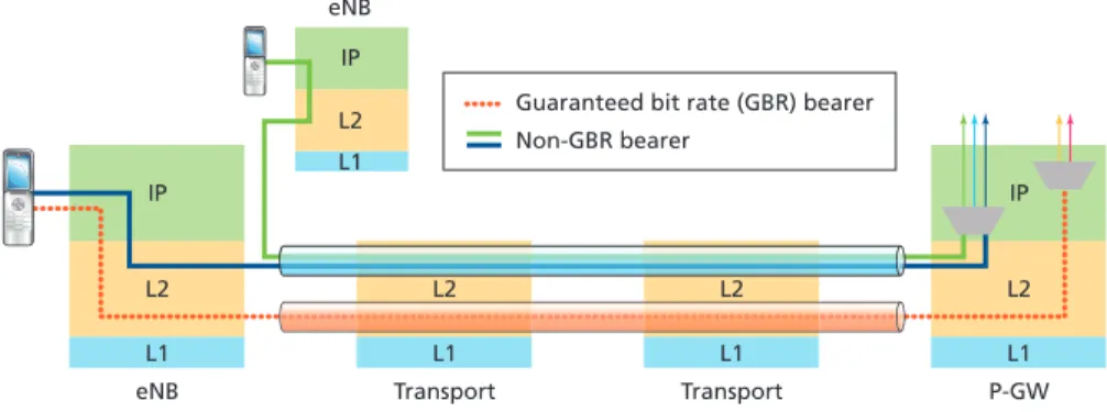
As illustrated in Figure 4, to guarantee delivery in terms of packet loss and delay, LTE requires that a bearer is established across the network.
Customer edge (CE)
User network interface (UNI)
Point-to-point EVC (E-LINE)
Source: MEF
Multipoint-to-multipoint EVC (E-LAN) Rooted multipoint EVC (E-TREE) Five attributes of Carrier Ethernet
Customer edge (CE)
Root
Leaf Carrier
Ethernet network
Leaf
Broadcast, multicast and unicast unknown Known unicast
Broadcast, multicast and unicast EVC
Figure 4. QoS in Layer 2 Backhaul
There may be many bearers which differ based on class of service, including some that do not require high quality Guaranteed Bit Rate (GBR). The backhaul network must be able to differentiate between the QoS requirements of the bearers and meet stringent requirements in terms of negligible packet loss and average delay of 10ms.
Synchronization for frequency and timing distribution
In order to transport real-time services over a packet network, an operator must provide a precise time signal to synchronize the traditional TDM services on the packet network without compromising service quality. The following network synchronization tools, techniques and protocols can be used: • Network Time Protocol (NTP) is a protocol to synchronize time of day across packet networks
that can operate over any backhaul technology
• IEEE 1588v2 is a protocol for accurately and precisely transferring both time of day and frequency across packet networks.
• Synchronous Ethernet is a technology similar in concept to SDH/SONET that provides frequency only; not phase and time. It requires a continuous path of Synchronous Ethernet-capable nodes and links.
• T1/E1s use SONET/SDH, where synchronization is provided naturally in TDM networks. • GPS is a Global Navigation Satellite System already deployed in some CDMA and WiMAX
networks that has Primary Reference Clock (PRC) frequency, phase, and time accuracy. GPS requires outdoor/rooftop access.
• Adaptive and Differential Clock Recovery are techniques for recovering or reconstructing the frequency of T1/E1 services transported across packet networks using circuit emulation. ¬ In the absence of a PRC, Adaptive Clock Recovery (ACR) monitors the packet stream
received from the packet switched network and calculates the clock frequency based on the rate of data received. This method is subject to Packet Delay Variation (PDV). ¬ Differential Clock Recovery (DCR) uses timestamps in packets and a common reference
clock frequency, making the recovered signals less subject to impairments due to PDV in the packet network. The common reference clock frequency for DCR can be delivered by 1588v2, or by a physical layer technology such as Synchronous Ethernet or radio carrier. • Network Timing Reference (NTR) is an established protocol that provides frequency and phase,
and is applicable for DSL access only.
Operators were surveyed to determine what network synchronization protocol they expect to use for Ethernet backhaul. Figure 5[2] shows that while T1/E1s are not disappearing, both Synchronous Ethernet and IEEE Standard 1588v2 are becoming increasingly important tools for synchronization.
L1 eNB
eNB
L2 IP
L1 L2 IP
L1 Transport
L2
L1 Transport Guaranteed bit rate (GBR) bearer
L2
L1 P-GW
L2 IP Non-GBR bearer
Figure 5. Synchronization survey for Ethernet backhaul sites
LTE on the horizon
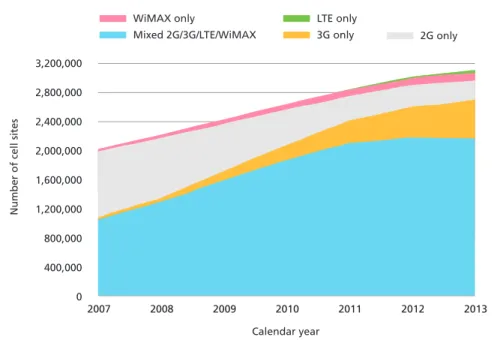
LTE is attracting phenomenal interest, with huge network build-outs being planned. But how quickly are mobile operators adopting LTE? Heavy Reading states that the vast majority of new LTE base stations will be deployed as an overlay to existing 3G cell sites. Through 2012, LTE will not generate many new cell sites. From a technology perspective this is also confirmed by Infonetics Research[3] whose forecast is summarized in Figure 6.
Mobile operators appear to be weighing the investment costs required against maintaining revenue streams as they explore their financial and service offering options.
Figure 6. Worldwide number of installed cell sites according to RAN type End 2008 End 2009
Ethernet backhaul sites by synchronization method
End 2010 End 2011 End 2012
NTP 1588 Synchronous Ethernet
T1/E1 GPS Adaptive clock recovery NTR
800,000 700,000 600,000 500,000
Cell sites serve
d
400,000 300,000 200,000 100,000 0
2007 2008 2009 2010 2011 2012 2013
Mixed 2G/3G/LTE/WiMAX 3G only 2G only
WiMAX only LTE only
3,200,000 2,800,000 2,400,000 2,000,000
Number of cell sites
Calendar year
Worldwide number of installed cell sites by RAN type
1,600,000 1,200,000
400,000 800,000
Mobile backhaul architecture and migration paths
Deployment timelines and technology choices will guide network transformations from 2G/3G to LTE. For operators with a very large 2G or 3G installed base, investments in legacy networks must be maintained when designing LTE transport architectures. Maintaining revenue from the existing 2G/3G network is critical to balance the investment in LTE.
By 2012, 40 percent of Ethernet backhaul deployments will have a hybrid component, either be-cause legacy TDM equipment provides extra capacity, or the operator does not want to alter their initial hybrid architecture[4]. A hybrid backhaul network that supports Ethernet and TDM allows the operator to delay upgrading their existing NodeBs to Ethernet. Therefore, an evolutionary approach, implementing new services in the current installed cell sites, allows operators to safely invest today for tomorrow’s LTE network.
LTE is ultimately expected to be a pure packet architecture, delivering voice through VoIP, and will include new high bandwidth mobile services like gaming and video. Increased traffic volume (100-300Mbps uplink) is enabled by increased spectrum efficiency. The network will transition to flat IP and an IP RAN. Its functionality will move closer to the user, from the Radio Network Controller (RNC) to eNodeB, with complexity incorporated into the edge router from the RNC to the Serving Gateway (sGW), and Packet Data Network Gateway (pGW).
LTE transport architectures can be at Layer 2 or Layer 3. Layer 2 can be implemented today, pro-viding flat IP for LTE. A Layer 3 approach may be desirable for the operator that wants to deliver content-aware services that require traffic/packet payload inspection. For both Layer 2 and Layer 3, Carrier Ethernet OAM, Packet Transport and Packet Synchronization are the key enablers. The uncertainty behind the rate of LTE migration suggests that different paths of evolution to LTE will take place across the globe. However, there is confidence that most of the world will migrate to LTE after 3G network coverage is completed. One certainty is that flexible backhaul options and technology ensure the ability to cope with different customer needs and strategies.
Transport for LTE backhaul
The LTE mobile layer is interconnected by aggregation and transport. In the mobile backhaul network, aggregation and transport is via L2 or L3 VPNs that connect the eNodeBs in the access mobile layer to the serving and packet data node gateways in the core (See Figure 7).
Figure 7. Transport for LTE backhaul
eNodeB
MMEs Transport layer
Aggregation and transport network
Core site
Mobile layer Mobile layer
X2
Control plane
Data plane
eNodeB SGW
L2/L3 VPNs
Two options used to carry traffic between eNodeB and Access Gateways are based on L2 and L3 architectures. Ethernet or MPLS technology (MPLS/T-MPLS/MPLS-TP) is used to backhaul traffic. Using Figure 8 as a reference, in L2 architectures the traffic between eNodeB and Access Gateways (aGW) (solid blue line) is classified according to MAC Address and VLAN. The Differentiated Services Code Point (DSCP) field can also be taken into account for QoS reasons. L2 provides transparent connectivity between the configured L3 endpoints (eNodeB and S/P Gateways). It operates on aggre-gate flows and provides transport-grade QoS, protection and OAM.
At the edge nodes connected to eNodeB and aGW in L3 architectures, the processing is according to the IP Header actions of IP Classification and forwarding (pink dotted line).
IP processing is done in eNodeB and S/P Gateways, while the transport network is transparent to the L3 layer. The hand off of traffic is done at the Ethernet level through VLAN Networking.
Figure 8. LTE backhauling options
Multipoint any-to-any connectivity
There is an increasing demand for mobile broadcasting services like mobile TV, news, weather, up-to-the-minute finance, public service announcements, emergencies, advertisements and subscription-based services. These broadcast services require a network that supports multipoint, any-to-any connectivity — the biggest change from 3G technology.
Ethernet is the common physical layer in Packet Transport equipment, LTE eNodeB and access gate-ways. Simplicity is achieved with a L2 backhauling transport network that is agnostic to applications; the transport function is separated from the protocols it transports.
S/P GWs ETH Ethernet/MPLS-TP ETH/IP ETH/IP 10 GE S1 GE ETH eNodeB GTP/UDP Application S/P GW Aggregation L2 backhauling S/P GWs IP IP/MPLS/MPLS-TP ETH/IP ETH/IP 10 GE S1 GE IP eNodeB L3 backhauling Access GTP/UDP Signal/PT eNB IP core IPv4/IPv6 IPv4/IPv6 Physical Data link Physical layer L2 Physical layer L2 Physical Data link Mobile Layer Transport Layer
2G/3G architectures primarily use point to point connections. However, LTE requires multipoint, any-to-any connectivity to support S1 interfaces between the eNodeB and the core network, and X2 interfaces that interconnect eNodeBs (See Figure 9). In LTE, E-LAN architectures in the transport network provide eNodeB connections through any-to-any communication on the X2 inter-face. This is necessary because the hand off is directly through eNodeB involvement without requiring a centralized system for coordination. LTE hand off can also be done in the aGW, as per 3GPP standards. In this case, it is the aGW itself that manag-es the any-to-any connectivity, while the transport network can imple-ment EVC (EVP-Line service).
Security
For leased Ethernet backhaul transport, the backhaul infrastructure becomes a shared/public network. This is a potential security threat to the backhaul network elements and a threat to the backhaul OAM, signaling and radio-bearer traffic. LTE introduces additional security concerns. In the case of sensitive new applications, user traffic on the S1 interfaces (in the backhaul and evolved packet core) may require protection. In 3G technology, the RNC encrypts the payload for the air interface providing first-mile protection. However, in 4G technology the encryption is between the user equipment and eNodeB. Security may also be needed for the LTE hand off between eNodeBs using the X2 interface to protect the IP addresses and to roam between 3GPP and non-3GPP networks. Investigation is underway on the potential use of IPSec on the X2 interfaces or on both X2 and S1 interfaces, and as network-level security on the cell-site gateway or application-level security on the eNodeB.
Encryption takes a heavy toll in terms of processing power and latency and increases costs, especially when en-crypting all of the traffic (>300Mb/s). It is not clear what level of security customers desire, but 3GPP specifies the implementation of IPSec on eNodeB[5].
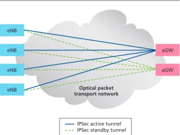
Encryption is better performed at the eNodeB. The Alcatel-Lucent eNodeB supports IPSec as a way to implement security against malicious users and to provide redundancy, as shown in Figure 10.
Figure 9. Any-to-any connectivity
SGW/MME
S1
S1 = Interface between an eNodeB and the core network X2 = Interface used to interconnect eNodeBs
X2
SGW/MME SGW/MME
eNB eNB
eNB
eNB
Figure 10. IPSec redundancy
aGW aGW
Optical packet transport network
IPSec active tunnel IPSec standby tunnel eNB
eNB eNB eNB
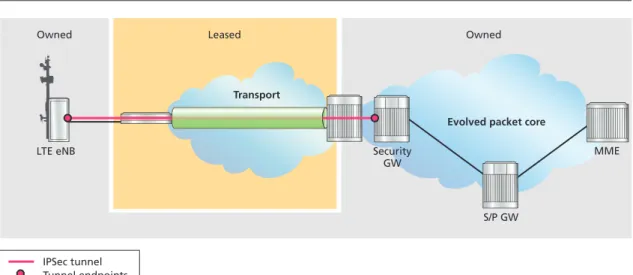
IPSec tunnels are carried over Carrier Ethernet/T-MPLS/MPLS-TP without being processed in the intermediate nodes. The transport network has its own protection based on ITU-T standards G.8032, and G.8131 to provide packet transport resiliency. As shown in Figure 11, a secure IPSec tunnel is created through the leased backhaul network, with end points in the operator-owned eNodeB and Security Gateway. The eNodeB manages the IPSec tunnel, which is transported trans-parently across the backhaul network.
Figure 11. IPSec transparency
Layer 2 LTE transport for mobile backhaul
There are many evolution paths to sustain LTE transport, all supported by the Alcatel-Lucent Mobile Evolution Transport Architecture (META). META is LTE ready[6], offering the service intelligence, flexibility, simplicity and cost-effectiveness necessary to serve the massive growth in demand for mobile broadband services while continuing to optimize 2G and 3G service delivery. This section demonstrates how L2 enables efficient support for 2G/3G and the introduction of LTE.
Figure 12 illustrates a 3G network connected to cell sites in the Access via microwave and fiber. Originally, Multi-service Provisioning Platform (MSPP) protection with the Alcatel-Lucent 1642 Edge Multiplexer (EM) in the metro network was connected to the SDH/SONET ring made up of the Alcatel-Lucent 1660 Synchronous Multiplexer (SM), 1662 Synchronous Multiplexer Compact (SMC) and/or 1663 ADM-universal (ADMu).
Microwave packet radio was added to this configuration with the Alcatel-Lucent 9500 Microwave Packet Radio (MPR). The MPR deploys a special block fragmentation that is especially suitable for low jitter applications such as VoIP. As a result, PDV is always the same, regardless of the length and the throughput of the concurrent lower priority Ethernet traffic, thus guaranteeing uniform jitter. The 1850 Transport Service Switch (TSS) is added into the Access, Aggregation and Core to provide Ethernet and T-MPLS/MPLS-TP functionality.
IPSec tunnel
Security GW LTE eNB
S/P GW
Evolved packet core Transport
Leased Owned
Owned
MME
Figure 12. Introduction of LTE to 2G/3G networks
With these additions, the operator gains the following functionality:
• Ethernet services (E-LINE, E-LAN, E-TREE) are fully supported as per MEF specifications • L2 VPNs optimize operations and can be reused for business services
• Transport-grade OAM and protection, including sub-50ms and SLA verification
• QoS supported at L2, delivering traffic with negligible packet loss, sub-50ms protection switching assisted by very fast data plane-based OAM and 10ms delay, controlling delay and jitter within the network. SLA verification is accomplished using the OAM mechanisms in Carrier Ethernet and MPLS-TP, which provide performance measurement in terms of packet loss, delay and jitter. • Reduced power consumption due to the ability to forward traffic at the lowest applicable layer This evolved network infrastructure fully supports 3G and is LTE-ready, as shown in Figure 13. L2 with MPLS-TP provides efficient carrier-grade backhaul for LTE. Ethernet services support X2 interfaces, and L2 VPNs can perform dynamic assignment of S-GWs to eNodeBs when needed.
9500 MPR 9500 MPR
1850 TSS 5
1850 TSS 5 1850 TSS 100c
Packet microwave
E1s Ethernet
1642 EM
1642 EM
166x
1850 TSS 320 RNC
S/P GW
Node B
Node B eNB
1850 TSS 5
Node B Node B
eNB Node B
IP/ETH MSPP/PTN protection
IP/ETH T-MPLS/MPLS-TP
protection
T-MPLS NG-SDH/SONET 1850 TSS 160
1850 TSS 160
MSPP protection
1850 TSS 160
1850 TSS 160
BSC RNC
Figure 13. Layer 2 VPN backhaul architecture
Layer 2 LTE transport customers
With more than 54 million customers in Japan, NTT DOCOMO is one of the world’s largest mobile communications operators. As service penetration and required speeds per user increase, they require a new mobile backhaul network combining packet and optical technologies. LTE is a key initiative in NTT DOCOMO’s global strategy and the proven Alcatel-Lucent Ethernet transport application will enable NTT DOCOMO to build a reliable and scalable packet-oriented backhaul network which satisfies the advanced requirements for sustainable growth.
This view is also acknowledged by Verizon Wireless. At the May 2009 Light Reading Live New York event, The Wonders of Packet-Optical Transport Evolution, Stuart Elby, Verizon Communications Inc. Vice President of network architecture and enterprise technology stated that, “Reducing costs will be one big effect of packet-optical, even at the edge of the radio network”[7].
9500 MPR 9500 MPR
1850 TSS 3 1850 TSS 100c Packet microwave
Ethernet
Ethernet
1850 TSS 320 S/P GW
eNB eNB
eNB eNB eNB
1850 TSS 5
1850 TSS 5
IP/ETH T-MPLS/MPLS-TP
protection T-MPLS/MPLS-TP
1850 TSS 160
1850 TSS 160
Conclusion
Mobile operators are motivated to lower their TCO as they bring in new revenue streams with bandwidth intensive and low delay applications enabled by LTE. Real-time applications that run over full-packet networks pose many challenges related to quality — challenges such as voice over packet. Therefore, the transport network chosen to backhaul LTE traffic must be cost-effective, highly reliable, and scalable to meet ever-increasing network capacity needs.
Layer 2 transport provides flat IP for LTE as shown in Figure 14. It simplifies operations by confining service support to the edges of the transport network, where end-points can be configured independently.
Figure 14. Layer 2 transport using T-MPLS/MPLS-TP
L2 transport and MPLS-TP give the best return on investment while providing full support for LTE operations and services, including VoIP and other real time services. The Alcatel-Lucent MPR and TSS support Ethernet OAM (801.ag and Y.1731), Synchronization (1588v2 and Synchronous Ethernet), circuit emulation services for TDM, E-LINE, E-TREE and E-LAN services, and also support IPSec transparently.
The Alcatel-Lucent evolution path minimizes technological risk. Operators can safely invest today in a Layer 2 transport network with the assurance that their assets can be reused tomorrow (or anytime in the future) for LTE.
S/P GW
MME MME
Converged transport network
Converged RAN Evolved packet core
Metro aggregation
Service
Access Core
E-Line E-Line/E-LAN (L2VPN) IP VPN (L3VPN)
Networking Ethernet T-MPLS/MPLS-TP IP/MPLS
Abbreviations
ACR Adaptive Clock Recovery aGW Access Gateway
CE Customer Edge
DCR Differential Clock Recovery DSCP Differentiated Services Code Point E-LAN Ethernet LAN
E-LINE Ethernet Private Line eNB or eNodeB Evolved Node B E-TREE Ethernet Private Tree GBR Guaranteed Bit Rate
L2 Layer 2
L3 Layer 3
LAN Local Area Network LTE Long Term Evolution MAC Media Access Control MEF Metro Ethernet Forum
META Mobile Evolution Transport Architecture NTP Network Time Protocol
NTR Network Timing Reference PDV Packet Delay Variation PRC Primary Reference Clock
PWE Pseudowire
pGW Packet Data Network Gateway RNC Radio Network Controller
S1 Interface between an eNodeB and the core network sGW Serving Gateway
S/P GW Serving or Packet Data Network Gateway SLA Service Level Agreement
TCO Total Cost of Ownership UNI User Network Interface VLAN Virtual LAN
X2 Interface used to interconnect eNodeBs
References
[1] MEF22 Mobile Backhaul Implementation Agreement, February 2009, http://metroethernetforum. org/page_loader.php?p_id=29
[2] Heavy Reading Ethernet Backhaul Tracker, March 2009
[3] Mobile Backhaul Equipment and Services Biannual Worldwide and Regional Market Size and Forecasts, Infonetics Research, May, 2009
[4] Analysis of Mobile Backhaul Equipment and Services Biannual Worldwide and Regional Market Size and Forecasts, page 19.
[5] 3GPP TS 33.210 / TS 33.310
[6] LTE Mobile Transport Evolution, July 2009
[7] Light Reading’s Unstrung – The 4G Authority, May 21, 2009, Verizon: Optical Equals Cheaper LTE. http://www.unstrung.com/document.asp?doc_id=177033
www.alcatel-lucent.com Alcatel, Lucent, Alcatel-Lucent and the Alcatel-Lucent logo are trademarks of Alcatel-Lucent. All other trademarks are the property of their respective owners.