AUSTRALIAN JOURNAL OF BASIC AND
Open Access Journal
Published BY AENSI Publication
© 2016 AENSI Publisher All rights reserved
This work is licensed under the Creative Commons Attribution International License (CC BY). http://creativecommons.org/licenses/by/4.0/
To Cite This Article: Usama M. Rashed., Characterization of Helium and Argon System. Aust. J. Basic & Appl. Sci., 10(10):
Characterization of Helium and Argon
Jet Generated by DBD S
Usama M. Rashed
Physics Department, Faculty of Science, Al-Azhar University,
Address For Correspondence:
Usama M. Rashed, Physics Department, Faculty of Science, Al Tel: + 21098460381; E-mail: [email protected]
A R T I C L E I N F O Article history:
Received 13 April 2016 Accepted 21 June 2016 Published 28 June 2016
Keywords:
Cold plasma, plasma jet , Dielectric probe, DBD, micro-discharges, bullet velocity.
Atmospheric pressure cold plasma has been widely used due to its important applications in various fields. It is a promising technology that is simpler to set
power cost, high density (> 1013 cm
important atmospheric pressure cold plasma is a plasma jet.
Plasma jet is a type of atmospheric pressure plasma devices that generates plasma outside the discharge feed gas tube under normal pressure by means of microwaves, high frequency or
Operating gas such as helium, argon, nitrogen, or air, can be used with plasma jets devices and a plasma plume is generated with a length depends on the applied voltage
Shao et al., 2011).
The plasma jet has recently attracted great attention b devices (Walsh et al., 2006; Lee et al
Stonies et al, 2004), which generate plasma plumes in surrounding air rat
AUSTRALIAN JOURNAL OF BASIC AND
APPLIED SCIENCES
8414 -2309 : 8178 EISSN
-ISSN:1991
Journal home page: www.ajbasweb.com
Publisher All rights reserved
This work is licensed under the Creative Commons Attribution International License (CC BY). http://creativecommons.org/licenses/by/4.0/
Characterization of Helium and Argon Atmospheric Pressure Cold Plasma Jet Generated by DBD
): 209-216, 2016
Helium and Argon Atmospheric Pressure
System
Azhar University, 11884, Cairo, Egypt
Usama M. Rashed, Physics Department, Faculty of Science, Al-Azhar University, 11884, Nasr City, Cairo, Egypt. mail: [email protected]
A B S T R A C T
Plasma jet is a type of atmospheric pressure plasma devices
plasma plume in the surrounding air and this property plays an important role in diverse applications. The main objective of this works is developing and characterizing of a simple atmospheric pressure cold plasma jet based on Heluim and Argon gas aim of optimizing it for useful applications. This cold plasma jet was generated by atmospheric pressure dielectric barrier discharge (DBD) system
power supply (amplitudes up to 15 kV, frequency 12 kHz). inner needle electrode inside a Pyrex tube with an outer sheet electrode the tube near its end. Characteristics of plasma jet were investigated using
current waveforms, plume current, bullet velocity and optical images of plasma jet at different applied voltages and gas flow rates. Voltage and current waveforms show a typical waveform of a dielectric barrier discharge with multiple current peaks of duration ranges from 1 µs to 5 µs which suggest that, the plasma tends to be a continuous DBD discharge. Optical images show that, the geometry and the shape of the plasma jet were found dependent on the applied voltage and gas flow rate. With the increase of the applied voltage, the length of jet increases and gradually tends to saturation. More than 5.5 cm plasma jet length for Helium and more than 3.5 cm plasma jet length for Argon were achieved. The plasma bullet velocity was estimated to reach a maximum value of 10X106 cm/sec for Helium plasma jet and 3.3 X10
for Argon plasma jet. Therefore such characteristic of plasma jet is useful in a Varity technological application.
INTRODUCTION
Atmospheric pressure cold plasma has been widely used due to its important applications in various fields. is a promising technology that is simpler to set-up, easier to operate, small size, low temperature, low electric
cm-3)and does not require vacuum equipments (Kikuchi important atmospheric pressure cold plasma is a plasma jet.
atmospheric pressure plasma devices that generates plasma outside the discharge under normal pressure by means of microwaves, high frequency or
Operating gas such as helium, argon, nitrogen, or air, can be used with plasma jets devices and a plasma plume length depends on the applied voltage, gas flow rate, and gas mixture
The plasma jet has recently attracted great attention because of the variety advantages et al., 2010; Georgescu, 2008; Begum et al., 2011;Shashurin , which generate plasma plumes in surrounding air rather than only in discharge gaps
Atmospheric Pressure Cold Plasma Jet Generated by DBD
ressure Cold Plasma
Azhar University, 11884, Nasr City, Cairo, Egypt.
atmospheric pressure plasma devices capable of launching a cold plasma plume in the surrounding air and this property plays an important role in diverse The main objective of this works is developing and characterizing of a eluim and Argon gas with the cold plasma jet was generated by atmospheric pressure dielectric barrier discharge (DBD) system powered by a pulsed dc power supply (amplitudes up to 15 kV, frequency 12 kHz). The system consists of an inner needle electrode inside a Pyrex tube with an outer sheet electrode wrapped around were investigated using voltage and , plume current, bullet velocity and optical images of plasma jet at
Voltage and current waveforms show a
with multiple current peaks of suggest that, the plasma tends to be a continuous DBD discharge. Optical images show that, the geometry and the shape of the plasma jet were found dependent on the applied voltage and gas flow rate. With the ge, the length of jet increases and gradually tends to saturation. More than 5.5 cm plasma jet length for Helium and more than 3.5 cm plasma jet length for Argon were achieved. The plasma bullet velocity was estimated to sec for Helium plasma jet and 3.3 X106 cm/sec jet. Therefore such characteristic of plasma jet is useful in a Varity
Atmospheric pressure cold plasma has been widely used due to its important applications in various fields. small size, low temperature, low electric (Kikuchi et al., 2004). One of
atmospheric pressure plasma devices that generates plasma outside the discharge pulsed direct current. Operating gas such as helium, argon, nitrogen, or air, can be used with plasma jets devices and a plasma plume , gas flow rate, and gas mixture (Xiong et al., 2009;
plasma jets are widely used in biological application 2013), surface decontamination (Chen
Shao et al., 2015) and deposition (Yao Lu and Laroussi (2006) described a repetition rates of a few kilohertz.
shows that the plasma plume is in fact a small bullet velocities. Plasma plume traveling with a speed of up to 10 are three consecutive discharge pulses. The first
second current pulse is linked to the discharge caused by the charge buildup on that, atmospheric pressure plasma jet
operated using quartz capillary tube with three distinct electrode configurations: conventional double dielectric electrodes for making dielectric barrier discharges, single dielectric
attached to the tube orifice. The jets generated by using the double dielectric electrodes three distinct discharge parts and of different origins. The plasma jet starting from the essentially the propagation of streamers induced by corona discharge. With one
be generated in both downstream and upstream directions significantly reduced voltage
(peak-bare metal electrode configuration which
the occurrence of a second streamer observed in the optica dependence of jet length can be reasonably accounted
atmospheric pressure plasma jet (APPJ) in air that is expected to be useful for polymer surface The plasma jet was produced by applying (10
external electrode has been found to be more effective in boosting the jet to a distance up to 30 mm even with a small flow rate of air. The characteristic of the proposed APPJ was investigated by measuring the effect of treatment on a PE film on the jet for different exposition time and distance from the nozzle. It has been confirmed that the jet can modify polymer film with a work distance o
Characterization of cold plasma jet is very important applications. In this paper, a very simple design of
system was constructed using a pulsed dc
system consists of an inner central needle electrode inside a Pyrex tube with an outer sheet electrode around the tube near its end. The electrical and optical
the optimum condition for operating control on the useful plasma jet applications.
2. Experimental Description:
Schematic diagram of the plasma jet is show was placed inside a 10cm long Pyrex glass electrode was a copper sheet of 20mm width
Fig
The electrodes were connected to a high
frequency 12 kHz). The plasma jet is operated with different high voltage pulses within and Argon were used as a working gas and injected at a flow rate
plasma jets are widely used in biological application (Lee et al., 2010; Rupf et al., 2010
Chen et al., 2006), surface modification (Wolter et al., 2009; Knoll Yao et al., 2011).
described a plasma pencil device driven by few hundred nanosecond wide pulses at repetition rates of a few kilohertz. Correlation between current-voltage characteristics and fast photography plasma plume is in fact a small bullet-like volume of plasma traveling at unusually high Plasma plume traveling with a speed of up to 105 m/ s is reported. I-V characteristics show that
pulses. The first current pulse is associated with a first discharge s linked to the launch of the plasma plume, and the third current pulse is discharge caused by the charge buildup on the dielectric surfaces of the electrodes. Jiang
atmospheric pressure plasma jet (APPJ) can protrude several centimes into the ambient air
quartz capillary tube with three distinct electrode configurations: conventional double dielectric electrodes for making dielectric barrier discharges, single dielectric electrode, and single bare metal
attached to the tube orifice. The jets generated by using the double dielectric electrodes were found consisting of parts and of different origins. The plasma jet starting from the
essentially the propagation of streamers induced by corona discharge. With one single electrode, plasma jets can be generated in both downstream and upstream directions simultaneously; and more importantly at a -to-peak value from 3.6 kV at 17 kHz), this is particularly the case with the bare metal electrode configuration which also helps promote the jet velocity. The typical jet velocity
streamer observed in the optical emission as well as the voltage and/or gas flow length can be reasonably accounted by a streamer mechanism. Tyata et al
atmospheric pressure plasma jet (APPJ) in air that is expected to be useful for polymer surface
applying (10- 30) kHz, (0 -20) kV AC source. The use of solenoid as an external electrode has been found to be more effective in boosting the jet to a distance up to 30 mm even with a characteristic of the proposed APPJ was investigated by measuring the effect of treatment on a PE film on the jet for different exposition time and distance from the nozzle. It has been confirmed that the jet can modify polymer film with a work distance of over 25mm.
Characterization of cold plasma jet is very important tool to have a better control on the plasma a very simple design of atmospheric cold plasma jet by dielectric barrier discharge
pulsed dc power supply (amplitudes up to 15 kV, frequency 12 kHz). inner central needle electrode inside a Pyrex tube with an outer sheet electrode
electrical and optical characterization was estimated with the aim of
operating this plasma jet device and the author speculates this study to be a good control on the useful plasma jet applications.
plasma jet is shown in Figure (1). A copper needle electrode of diameter Pyrex glass tube of inner diameter 4 mm and outer diameter 6 mm. The outer of 20mm width wrapped around the outer surface of the glass tube.
Fig. 1: Schematic diagram of the plasma jet.
The electrodes were connected to a high voltage pulsed dc power supply (amplitudes up to 15 kV, . The plasma jet is operated with different high voltage pulses within 3
working gas and injected at a flow rate up to 5 L/min through the annular space ; Nastuta and Topala, ., 2009; Knoll et al., 2014;
hundred nanosecond wide pulses at voltage characteristics and fast photography like volume of plasma traveling at unusually high characteristics show that, there pulse is associated with a first discharge initiation, the launch of the plasma plume, and the third current pulse is associated with a Jiang et al. (2009) showed into the ambient air. APPJ was quartz capillary tube with three distinct electrode configurations: conventional double dielectric electrode, and single bare metal electrode were found consisting of parts and of different origins. The plasma jet starting from the active electrodes is single electrode, plasma jets can simultaneously; and more importantly at a , this is particularly the case with the also helps promote the jet velocity. The typical jet velocity of 104 m/ s, l emission as well as the voltage and/or gas flow et al. (2012) reported an atmospheric pressure plasma jet (APPJ) in air that is expected to be useful for polymer surface modification. 20) kV AC source. The use of solenoid as an external electrode has been found to be more effective in boosting the jet to a distance up to 30 mm even with a characteristic of the proposed APPJ was investigated by measuring the effect of treatment on a PE film on the jet for different exposition time and distance from the nozzle. It has been
to have a better control on the plasma by dielectric barrier discharge amplitudes up to 15 kV, frequency 12 kHz). The inner central needle electrode inside a Pyrex tube with an outer sheet electrode wrapped with the aim of obtaining this study to be a good
. A copper needle electrode of diameter 2mm inner diameter 4 mm and outer diameter 6 mm. The outer
e of the glass tube.
between two electrodes. After passing gas in the inner volume of the glass tube, plasma jet is spread out glass tube with long plume. Voltage was measured using a resistive potential divider (1
measured by measuring a voltage across 1 recorded by a digital storage oscilloscope (
measure plume velocity. This probe is made of a small Al foil pasted on a dielectric sheet of Perspex. The advantage of this probe is the possibility of placing it close to the outlet of the plasma jet without arcing. The dielectric probe is connected to the ground through a
propagation along the jet axis. As the plasma plume touches the probe, the whole system (plasma, probe, and resistor) builds RC circuit and the current measured across the resistor is the total curre
measure the velocity of the plasma at different distances from the tip of
measured at those distances and a time delay between the consecutive plume propagation axis is estimated. The outer
plasma plume.
3.1 Voltage and current waveforms
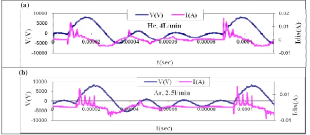
The voltage-current waveforms of the Figure (2) shows one of the typical voltage
shows a typical waveform of a dielectric barrier discharge.
(a)
(b)
Fig. 2: One of the typical v
The discharge current (Idis) is caused by charge accumulation on the dielectric surface. This surface charge
creates an electric potential that opposes the applied voltage and, as a result, limits the discharge current and prevents the glow-to-arc transition.
to the capacitive coupling of the circuits with dielectric tube and discharged gas (Kasih, 2007). observed from figure (2) that, at least two current peaks for Helium plasma and multiple curren Argon plasma appear in the current waveforms with a pulse duration range
characteristics suggest that, the plasma tends to be a continuous DBD discharge (Massines
of a filamentary discharge whose current is characterized by multiple current pulses of a series of micro discharges with a typical micro-discharge current pulse width of 100 ns (Tang
3.2 optical Characteristics:
Images of a typical plasma jet created in He flow rates are taken to get the optimum condition images of plasma jet at 9 kV applied voltage
The initial discharge filaments in the DBD gap are found to be transited into diffusion discharges or glow like discharges by the flowing gas through the DBD gap and a plasma jet is formed in the outlet of the tube simultaneously. Obviously from figure (
core and the tail. Helium jet has only two regions from the beginning of the jet at the tip of th
between two electrodes. After passing gas in the inner volume of the glass tube, plasma jet is spread out glass Voltage was measured using a resistive potential divider (1-1000) and current was a voltage across 100Ω resistance connector. The voltage and current signals were oscilloscope (GWinsTEX GDs-1072-u,70MHZ). A dielectric probe is used to . This probe is made of a small Al foil pasted on a dielectric sheet of Perspex. The advantage of this probe is the possibility of placing it close to the outlet of the plasma jet without arcing. The dielectric probe is connected to the ground through a 2.5 kΩ resistor and placed at different
propagation along the jet axis. As the plasma plume touches the probe, the whole system (plasma, probe, and he current measured across the resistor is the total current of the plasma jet. measure the velocity of the plasma bullet from the plasma jet current along the axis, a dielectric probe is placed
from the tip of tube along the jet axis, and the jet current pass through dielectric probe and a time delay between the consecutive distances of the probe on the plasma n axis is estimated. The outer tip of glass tube is used as the reference
RESULTS AND DISCUSSION
Voltage and current waveforms:
current waveforms of the plasma jet were measured at different applied voltage ( the typical voltage-current waveforms of (a) Helium and (b) Argon a typical waveform of a dielectric barrier discharge.
voltage-current waveforms of (a) Helium and (b) Argon
) is caused by charge accumulation on the dielectric surface. This surface charge creates an electric potential that opposes the applied voltage and, as a result, limits the discharge current and Damped oscillations noticed on voltage and current waveforms might be due to the capacitive coupling of the circuits with dielectric tube and discharged gas (Kasih, 2007).
that, at least two current peaks for Helium plasma and multiple curren Argon plasma appear in the current waveforms with a pulse duration ranges from 1 to 5 characteristics suggest that, the plasma tends to be a continuous DBD discharge (Massines
of a filamentary discharge whose current is characterized by multiple current pulses of a series of micro discharge current pulse width of 100 ns (Tang et al., 2010).
a typical plasma jet created in Helium and Argon gases at different applied voltage
to get the optimum condition of plasma jet operation for the two gases. Figure (3) show kV applied voltage for (a) Helium at 4 L/min and (b) Argon at 2.5 L/min.
The initial discharge filaments in the DBD gap are found to be transited into diffusion discharges or glow like discharges by the flowing gas through the DBD gap and a plasma jet is formed in the outlet of the tube
rom figure (3), three different regions can be observed for argon jet; the cone, the nly two regions without the cone region. The cone region
tip of the tube to the core region with a conical shape of length ranges from between two electrodes. After passing gas in the inner volume of the glass tube, plasma jet is spread out glass
1000) and current was resistance connector. The voltage and current signals were dielectric probe is used to . This probe is made of a small Al foil pasted on a dielectric sheet of Perspex. The advantage of this probe is the possibility of placing it close to the outlet of the plasma jet without arcing. The placed at different distances of plume propagation along the jet axis. As the plasma plume touches the probe, the whole system (plasma, probe, and nt of the plasma jet. To from the plasma jet current along the axis, a dielectric probe is placed pass through dielectric probe was of the probe on the plasma tip of glass tube is used as the reference distance (z=0) of the
ere measured at different applied voltage (3-10 kVs). rgon plasma jets which
Argon plasma jets.
) is caused by charge accumulation on the dielectric surface. This surface charge creates an electric potential that opposes the applied voltage and, as a result, limits the discharge current and iced on voltage and current waveforms might be due to the capacitive coupling of the circuits with dielectric tube and discharged gas (Kasih, 2007). It can be that, at least two current peaks for Helium plasma and multiple current peaks for from 1 to 5 µs. These characteristics suggest that, the plasma tends to be a continuous DBD discharge (Massines et al., 2003), instead of a filamentary discharge whose current is characterized by multiple current pulses of a series of
micro-., 2010).
at different applied voltage and different et operation for the two gases. Figure (3) shows
Argon at 2.5 L/min.
The initial discharge filaments in the DBD gap are found to be transited into diffusion discharges or glow-like discharges by the flowing gas through the DBD gap and a plasma jet is formed in the outlet of the tube
to 2cm. This region seems to be sharper with the increase in the applied voltage
Helium jet and extends from the cone region to the tail region for Argon plasma jet cylindrical shape has a diameter about
region has an irregular shape with low intensity rather than Benabbas et al., 2014.
Fig. 3: Images of plasma jet at applied voltage 9 kV for
It was found that, the plasma jet is only created when the inner electrode is the active electrode presented results were performed with the outer electrode grounded configuration.
applied potential varies with time leading to
voltage. At the ground electrode, the potential is fixed, an important amount of charge accumulated on the inner surface of the dielectric barrier (Pyrex
charge overflow beyond the ground electrode leads to the development of a self
This promotes the charged species movement along the axis of the gas flow from the active electrode to the ground electrode and ignites plasma beyond the ground electrodes; an extensive glow discharge is created in this area and a more pronounced plasma jet length is then obtained.
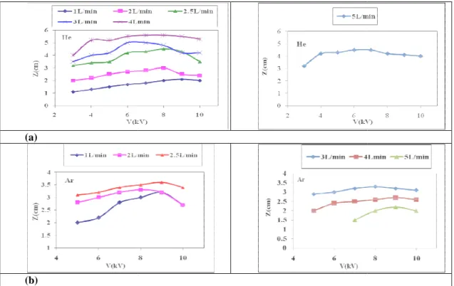
The geometry and the shape of the plasma jet were found dependent on the applied voltage an rate. Figure (4) shows the effect of applied voltage on
gas flow rates. It was found that, 3kV and 5 kV are the minimum applied voltages plasma jet for Helium and Argon respectively
voltage until reached maximum value then it saturate Helium and more than 3.5 cm for Ar
reaching the voltage value inducing the electrical breakdown of the gas, more energy is transferred into the discharge area. When the applied voltage increases, more energetic species are created and their pro
energy allows them to penetrate deeper into the surrounding air, leading to the formation of an extended plasma jet. This behavior is in agreement to
Helium and 2.5 L/min for Argon at applied voltage 9 kV are the optimum condition that give a larger plasma jet length.
sharper with a larger optical intensity rather than other r
applied voltage. The core region is extends from the tip of the tube to the tail region elium jet and extends from the cone region to the tail region for Argon plasma jet. Th
cylindrical shape has a diameter about 5 mm for helium and about 1.5 mm for Argon. The with low intensity rather than other regions. This behavior is in a
Images of plasma jet at applied voltage 9 kV for (a)Helium, 4 L/min and (b) Argon,
e plasma jet is only created when the inner electrode is the active electrode presented results were performed with the outer electrode grounded configuration. At the active electrode, the applied potential varies with time leading to ignite discharge and create charges during the
the potential is fixed, an important amount of charge accumulated on the inner Pyrex tube), underneath this electrode, creating then a charge overflow. This charge overflow beyond the ground electrode leads to the development of a self-biasing voltage in this region. This promotes the charged species movement along the axis of the gas flow from the active electrode to the trode and ignites plasma beyond the ground electrodes; an extensive glow discharge is created in this area and a more pronounced plasma jet length is then obtained.
The geometry and the shape of the plasma jet were found dependent on the applied voltage an effect of applied voltage on (a) Helium and (b) Argon plasma jet length
that, 3kV and 5 kV are the minimum applied voltages required
Argon respectively. The plasma jet length increase with the increase of applied until reached maximum value then it saturates or slightly decreases. It reaches more than 5.5 cm for and more than 3.5 cm for Argon and these results are very useful in plasma jet
reaching the voltage value inducing the electrical breakdown of the gas, more energy is transferred into the discharge area. When the applied voltage increases, more energetic species are created and their pro
energy allows them to penetrate deeper into the surrounding air, leading to the formation of an extended plasma is in agreement to Shao et al. (2011). These results suggests that, flow rates of
at applied voltage 9 kV are the optimum conditions for operating our design other regions and increases tube to the tail region for This region is a regular The tail region is the last This behavior is in agreement with
Helium, 4 L/min and (b) Argon, 2.5 L/min.
e plasma jet is only created when the inner electrode is the active electrode so, all At the active electrode, the charges during the pulse of the applied the potential is fixed, an important amount of charge accumulated on the inner en a charge overflow. This biasing voltage in this region. This promotes the charged species movement along the axis of the gas flow from the active electrode to the trode and ignites plasma beyond the ground electrodes; an extensive glow discharge is created in this
(a)
(b)
Fig. 4: The effect of applied voltage on the plasma jet length for
3.3 Velocity of plume:
To understand plasma jet spreading
important. The dielectric probe was placed at different and the plume current was measured at those
dielectric probe were measured at different applied voltage and different shows the plume current waveforms
flow rate for different two distances a time delay between the consecutive
delay for Helium is shorter than the time delay for Argon. in axial distance.
(a)
Fig. 5: The plume current waveforms of (a) Helium jet at 4L/min flow rate and (b) Argon rate for different two position along the jet axis at
The peak current of plasma plume (I jet’s axis for Helium and Argon plasma jet
increases with the increase in applied voltage and decreases with the increase in
effect of applied voltage on the plasma jet length for (a) Helium and (b) Argon at different gas flow rates.
spreading in the ambient atmosphere, the study of the plasma probe was placed at different distances (Z) from the tip of the tube current was measured at those distances as shown in figure (1). The plume
were measured at different applied voltage and different distances along the jet axis. s of plasma jet for (a) Helium at 4L/min flow rate and
distances (1cm and 2 cm) along the jet axis at 8 kV applied voltage. a time delay between the consecutive distances of the probe on the plasma plume propagation axis.
an the time delay for Argon. The peak of plume current decreases with the increase
(b)
current waveforms of (a) Helium jet at 4L/min flow rate and (b) Argon rate for different two position along the jet axis at 8 kV applied voltage
of plasma plume (Ipp) as a function of applied voltage at different probe’s
rgon plasma jet are shown in Figure (6). It was noticed that, the peak current increases with the increase in applied voltage and decreases with the increase in probe’s
(a) Helium and
in the ambient atmosphere, the study of the plasma plume velocity is from the tip of the tube along the jet axis, plume current (Ip) through along the jet axis. Figure (5) and (b) Argon at 2.5 L/min kV applied voltage. The figure shows of the probe on the plasma plume propagation axis. The time eak of plume current decreases with the increase
current waveforms of (a) Helium jet at 4L/min flow rate and (b) Argon jet at 2.5 L/min flow kV applied voltage
axis. The increase of peak current with plasma jet which creates more energetic current with the increase in probe’s channel behind the head of the plasma bullet
(a)
Fig. 6: The peak plume current as a function of applied voltage at different for (a) Helium jet at
The velocity of the plasma plume
distances of the probe and the time difference between the jet current peaks for The plasma plume velocity (bullet velocity, v)
Figure (7) shows the velocities of (a)
axial distance along the jet’s axis at different applied voltage with the increase in axial distance Z
(a)
Fig. 7: The velocities of (a) Helium (4 L/min) distance
The maximum plasma bullet velocity
bullet velocity increases with the increase in applied voltage. This can be attributed to the increase in power consumed which increases the kinetic energy of the accelerated charged particle.
with the increase in axial distance a
charged particle and the increase of recombination rate due to the collision with atoms of surrounding To explain the high plume propagation velocity outside the tub
electric field based on a photoionization In this model, the head of a cathodedirected
forward, it leaves behind a quasineutral ionized channel head consists of a small sphere, which has space suppose that a single photoelectron is created
influence of the field set up by the space charge, the electron is accelerated towards the sphere and an avalanche is initiated. In moving toward the sphere, the electron forms an avalanche
up to the sphere is sufficient, the electrons
. The increase of peak current with the increase in applied voltage is due to the increase in which creates more energetic charged particles contributing in plume current
probe’s distances along the jet’s axis shows that, there is a low density plasma channel behind the head of the plasma bullet (Begum et al., 2011).
(b)
current as a function of applied voltage at different probe’s position (a) Helium jet at 4L/min flow rate and (b) Argon jet at 2.5 L/min flow rate
plume is calculated by measuring the spatial difference between two consecutive probe and the time difference between the jet current peaks for those distances
(bullet velocity, v) was measured at different axial distance along the jet’s axis (a) Helium (4 L/min) and (b) Argon (2.5 l/min) plasma
at different applied voltages. It was noticed that, the bullet velocity axial distance Z until reaches maximum value then it gradually decreases.
(b)
he velocities of (a) Helium (4 L/min) and (b) Argon (2.5 l/min) plasma bullet(v) distance (Z) along the jet’s axis at different applied voltage.
velocity is 10X106 cm/sec for Helium and 3.3 X106 cm/ sec for argon. velocity increases with the increase in applied voltage. This can be attributed to the increase in power
the kinetic energy of the accelerated charged particle. The decrease of bullet velocity with the increase in axial distance after maximum can be ascribed to the decrease of the kinetic energy of the charged particle and the increase of recombination rate due to the collision with atoms of surrounding
high plume propagation velocity outside the tube, the streamer propagation model in low electric field based on a photoionization assumption (Dawson and Winn 1965; Qin and Pasko 2014
model, the head of a cathodedirected streamer is a sphere, containing n+ positive
quasineutral ionized channel. Assume that at a given instant of time, the streamer consists of a small sphere, which has space charge n+. Because of photon emission from the streamer, suppose that a single photoelectron is created at a suitable distance from the center of the sphere
influence of the field set up by the space charge, the electron is accelerated towards the sphere and an avalanche is initiated. In moving toward the sphere, the electron forms an avalanche of multiplication
up to the sphere is sufficient, the electrons neutralize the positive charge but leave behind a new positive crease in power pumped to contributing in plume current. The decrease of peak there is a low density plasma
probe’s position along the jet’s axis (b) Argon jet at 2.5 L/min flow rate.
spatial difference between two consecutive distances.
axial distance along the jet’s axis. plasma bullet as a function of t was noticed that, the bullet velocity increases until reaches maximum value then it gradually decreases.
plasma bullet(v) as a function of axial along the jet’s axis at different applied voltage.
cm/ sec for argon. The velocity increases with the increase in applied voltage. This can be attributed to the increase in power The decrease of bullet velocity the decrease of the kinetic energy of the charged particle and the increase of recombination rate due to the collision with atoms of surrounding air.
The streamer will stop propagating when the electrostatic energy of the sphere of charges is lost via the ionization processes.
Conclusions:
Helium and Argon non-thermal atmospheric pressure plasma jet has been created using DBD discharge configuration. It has been found that the shape and the length of the plasma jet are dependent on both applied voltage and the gas flow rate. A plasma jet with 5.5 cm for Helium and 3.5 cm for Argon has been obtained. The maximum plasma plume velocity was estimated to be 10X106 cm/sec for Helium and 3.3 X106 cm/ sec for argon. Therefore, the plasma jet device with this characteristic can be used in many technological applications such as etching, sterilization, and surface modification, etc. The future work will be attempt to construct a cold plasma jet source with multiple plasma plumes merge together to form a uniform plasma layer of large area to be used in surface treatment.
ACKNOWLEDGMENTS
The authors would like to thank all members of Center of Plasma Technology and Plasma Physics Laboratory, Physics Department, Faculty of Science, Al-Azhar University, for their assistance, kind support, great interest and valuable scientific discussions and comments.
REFERENCES
Begum, A., M. Laroussi and M.R. Pervez, 2011. Dielectric Probe: a New Electrical Diagnostic Tool for Atmospheric Pressure Non-Thermal Plasma Jet. International Journal of Engineering & Technology IJET-IJENS, 11(3): 209-215.
Benabbas, M.T., S. Sahli, A. Benhamouda and S. Rebiai, 2014. Effects of the Electrical Excitation Signal Parameters on the Geometry of an Argon-Based Non-Thermal Atmospheric Pressure Plasma Jet. Nanoscale Research Letters, 9:697, 1-5.
Chen, G., S. Chen, M. Zhou, W. Feng, W. Gu and S. Yang, 2006. The Preliminary Discharge Characterization of a Nobal APGD Plume and its Application in Organic Contaminated Degradation. Plasma Sources Science Technology, 15(603): 603-608.
Dawson, G.A. and W.P. Winn, 1965. A Model for Streamer Propagation. Zeitschrift fur Physik, 183: 159-171.
Georgescu, N., 2008. High Voltage Pulsed Cold Atmospheric Plasma Jets: Electrical characterization. Romanian Reports in Physics, 60(4): 1025-1032.
Jiang, N., A. Ji and Z. Cao, 2009. Atmospheric Pressure Plasma Jet: Effect of Electrode Configuration, Discharge Behavior, and its Formation Mechanism. Jornal of Applied Physics, 106: 013308,1-7.
Kasih, T.P., 2007. Development of Noval Potential of Plasma Polymerization Techniques for Surface Modefication, PHD thesis, Graduate School of Engineering Gunma University.
Kikuchi, T., Y. Hasegawa and H. Shirai, 2004. Rf Microplasma Jet at Atmospheric Pressure: Characterization and Application to Thin Film Processing. Journal of Physics D: Applied Physics, 37: 1537-1543.
Knoll, A.J., P. Luan, E.A.J. Bartis, C. Hart, Y. Raitses and G.S. Oehrlein, 2014. Real Time Characterization of Polymer Surface Modifications by an Atmospheric-Pressure Plasma Jet: Electrically Coupled Versus Remote Mode. Applied physics letters, 105: 171601, 1-4.
Lee, W., S.H. Nam, A.H. Mohamed, G.C. Kim and J.K. Lee, 2010. Atmospheric Pressure Plasma Jet Composed of Three Electrodes: Application to Tooth Bleaching. Plasma Processes and Polymers, 7: 274-280.
Lu, X. and M. Laroussi, 2006. Dynamic of an Atmospheric Pressure Plasma Plume Generated by Submicrosecond Voltage Pulses. Journal of Applied Physics, 100: 063302,1-6.
Massines, F., P. Segur, N. Gherardi, C. Khamphan and A. Ricard, 2003. Physics and Chemistry in a Glow Dielectric Barrier Discharge at Atmospheric Pressure: Diagnostics and Modeling. Surface and Coatings Technology, 174 -175: 8-14.
Nastuta, A.V. and I. Topala, 2013. Atmospheric pressure plasma jet-Living tissue interface: Electrical, optical, and spectral characterization. Journal of Applied Physics, 113: 183302,1-6.
Qin, J. and V.P. Pasko, 2014. On the propagation of streamers in electrical discharges. J. Physics D: Applied Physcis, 47: 435202, 1-9.
Shao, T., Yixiao Zhou, C. Zhang, W. Yang, Z. Niu and C. Ren, 2015. Surface Modification of Polymethyl-methacrylate Using Atmospheric Pressure Argon Plasma Jets to Improve Surface Flashover Performance in Vacuum. IEEE Transactions on Dielectrics and Electrical Insulation, 22(3): 1747-1754.
Shao, X.J., G.J. Zhang, J.Y. Zhan and H.B. Mu, 2011. Investigation on Spurt Length of Atmospheric-Pressure Plasma Jets. IEEE Transactions on Plasma Science, 39(11): 2240-2341.
Shashurin, A., M.N. Shneider, A. Dogariu, R.B. Miles and M. Keidar, 2009. Temporal behavior of cold atmospheric plasma jet. Applied Physics Letters, 94: 231504 94,1-3.
Stonies, R., S. Schermer, E. Voges and J.A. C. Broekaert, 2004. A New Small Microwave Plasma Torch. Plasma Sources Science and Technology, 13(4): 604-611.
Tang, J., Y. Duan and W. Zhao, 2010. Characterization and Mechanism Studies of Dielectric Barrier Discharges Generated at Atmospheric Pressure. Applied Physics Letters, 96: 191503,1-3.
Tyata, R.B., D.P. Subedi, A. Shrestha and D. Baral, 2012. Development of Atmospheric Pressure Plasma Jet in Air. Kathmandu University Journal of Science, Engineering and Technology, 8(1): 15-22.
Walsh, J.L., J.J. Shi and M.G. Kong, 2006. Contrasting Characteristics of Pulsed and sinusoidal cold atmospheric plasma jets. Appl. Phys. Lett., 88: 171501, 1-3.
Wolter, M., S. Bornholdt, M. Häckel and H. Kersten, 2009. Atmospheric Pressure Plasma Jet for Treatment of Polymers. Journal of Achievements in Materials and Manufacturing Engineering, 37(2): 730-734.
Xiong, Q., X. Lu, K. Ostrikov, Z. Xiong, Y. Xian, F. Zhou, C. Zou, J. Hu, W. Gong and Z. Jiang, 2009. Length Control of He Atmospheric Plasma Jet Plumes: Effects of Discharge Parameters and Ambient Air. Physics of Plasmas, 16: 043505.