R
Tutorial
Xilinx is disclosing this Document and Intellectual Property (hereinafter “the Design”) to you for use in the development of designs to operate on, or interface with Xilinx FPGAs. Except as stated herein, none of the Design may be copied, reproduced, distributed, republished, downloaded, displayed, posted, or transmitted in any form or by any means including, but not limited to, electronic, mechanical,
photocopying, recording, or otherwise, without the prior written consent of Xilinx. Any unauthorized use of the Design may violate copyright laws, trademark laws, the laws of privacy and publicity, and communications regulations and statutes.
Xilinx does not assume any liability arising out of the application or use of the Design; nor does Xilinx convey any license under its patents, copyrights, or any rights of others. You are responsible for obtaining any rights you may require for your use or implementation of the Design. Xilinx reserves the right to make changes, at any time, to the Design as deemed desirable in the sole discretion of Xilinx. Xilinx assumes no obligation to correct any errors contained herein or to advise you of any correction if such be made. Xilinx will not assume any liability for the accuracy or correctness of any engineering or technical support or assistance provided to you in connection with the Design.
THE DESIGN IS PROVIDED “AS IS” WITH ALL FAULTS, AND THE ENTIRE RISK AS TO ITS FUNCTION AND IMPLEMENTATION IS WITH YOU. YOU ACKNOWLEDGE AND AGREE THAT YOU HAVE NOT RELIED ON ANY ORAL OR WRITTEN INFORMATION OR ADVICE, WHETHER GIVEN BY XILINX, OR ITS AGENTS OR EMPLOYEES. XILINX MAKES NO OTHER WARRANTIES, WHETHER EXPRESS, IMPLIED, OR STATUTORY, REGARDING THE DESIGN, INCLUDING ANY WARRANTIES OF MERCHANTABILITY, FITNESS FOR A PARTICULAR PURPOSE, TITLE, AND NONINFRINGEMENT OF THIRD-PARTY RIGHTS.
IN NO EVENT WILL XILINX BE LIABLE FOR ANY CONSEQUENTIAL, INDIRECT, EXEMPLARY, SPECIAL, OR INCIDENTAL DAMAGES, INCLUDING ANY LOST DATA AND LOST PROFITS, ARISING FROM OR RELATING TO YOUR USE OF THE DESIGN, EVEN IF YOU HAVE BEEN ADVISED OF THE POSSIBILITY OF SUCH DAMAGES. THE TOTAL CUMULATIVE LIABILITY OF XILINX IN CONNECTION WITH YOUR USE OF THE DESIGN, WHETHER IN CONTRACT OR TORT OR OTHERWISE, WILL IN NO EVENT EXCEED THE AMOUNT OF FEES PAID BY YOU TO XILINX HEREUNDER FOR USE OF THE DESIGN. YOU ACKNOWLEDGE THAT THE FEES, IF ANY, REFLECT THE ALLOCATION OF RISK SET FORTH IN THIS AGREEMENT AND THAT XILINX WOULD NOT MAKE AVAILABLE THE DESIGN TO YOU WITHOUT THESE LIMITATIONS OF LIABILITY.
The Design is not designed or intended for use in the development of on-line control equipment in hazardous environments requiring fail-safe controls, such as in the operation of nuclear facilities, aircraft navigation or communications systems, air traffic control, life support, or weapons systems (“High-Risk Applications”). Xilinx specifically disclaims any express or implied warranties of fitness for such High-Risk Applications. You represent that use of the Design in such High-Risk Applications is fully at your risk.
Copyright © 1995-2007 Xilinx, Inc. All rights reserved. XILINX, the Xilinx logo, and other designated brands included herein are trademarks of Xilinx, Inc. PowerPC is a trademark of IBM, Inc. All other trademarks are the property of their respective owners.
Preface
About This Tutorial
About the In-Depth Tutorial
This tutorial gives a description of the features and additions to Xilinx® ISE™ 10.1. The primary focus of this tutorial is to show the relationship among the design entry tools, Xilinx and third-party tools, and the design implementation tools.
This guide is a learning tool for designers who are unfamiliar with the features of the ISE software or those wanting to refresh their skills and knowledge.
You may choose to follow one of the three tutorial flows available in this document. For information about the tutorial flows, see“Tutorial Flows.”
Tutorial Contents
This guide covers the following topics.
• Chapter 1,“Overview of ISE and Synthesis Tools,”introduces you to the ISE primary user interface, Project Navigator, and the synthesis tools available for your design.
• Chapter 2,“HDL-Based Design,” guides you through a typical HDL-based design procedure using a design of a runner’s stopwatch.
• Chapter 3,“Schematic-Based Design,” explains many different facets of a schematic-based ISE design flow using a design of a runner’s stopwatch. This chapter also shows how to use ISE accessories such as StateCAD, CORE Generator™, and ISE Text Editor.
• Chapter 4,“Behavioral Simulation,” explains how to simulate a design before design implementation to verify that the logic that you have created is correct.
• Chapter 5,“Design Implementation,” describes how to Translate, Map, Place, Route (Fit for CPLDs), and generate a Bit file for designs.
• Chapter 6,“Timing Simulation,” explains how to perform a timing simulation using the block and routing delay information from the routed design to give an accurate assessment of the behavior of the circuit under worst-case conditions.
• Chapter 7,“iMPACT Tutorial” explains how to program a device with a newly created design using the IMPACT configuration tool.
Tutorial Flows
This document contains three tutorial flows. In this section, the three tutorial flows are outlined and briefly described, in order to help you determine which sequence of chapters applies to your needs. The tutorial flows include:
• HDL Design Flow
• Schematic Design Flow
• Implementation-only Flow
HDL Design Flow
The HDL Design flow is as follows:
• Chapter 2,“HDL-Based Design”
• Chapter 4,“Behavioral Simulation”
Note that although behavioral simulation is optional, it is strongly recommended in this tutorial flow.
• Chapter 5,“Design Implementation”
• Chapter 6,“Timing Simulation”
Note that although timing simulation is optional, it is strongly recommended in this tutorial flow.
• Chapter 7,“iMPACT Tutorial”
Schematic Design Flow
The Schematic Design flow is as follows:
• Chapter 3,“Schematic-Based Design”
• Chapter 4,“Behavioral Simulation”
Note that although behavioral simulation is optional, it is strongly recommended in this tutorial flow.
• Chapter 5,“Design Implementation”
• Chapter 6,“Timing Simulation”
Note that although timing simulation is optional, it is strongly recommended.
• Chapter 7,“iMPACT Tutorial”
Implementation-only Flow
The Implementation-only flow is as follows:
• Chapter 5,“Design Implementation”
• Chapter 6,“Timing Simulation”
Note that although timing simulation is optional, it is strongly recommended in this tutorial flow.
Additional Resources
To find additional documentation, see the Xilinx website at:
http://www.xilinx.com/literature.
To search the Answer Database of silicon, software, and IP questions and answers, or to create a technical support WebCase, see the Xilinx website at:
Preface: About This Tutorial
About the In-Depth Tutorial . . . 3
Tutorial Contents . . . 3
Tutorial Flows . . . 4
HDL Design Flow . . . . 4
Schematic Design Flow . . . 4
Implementation-only Flow . . . 4
Additional Resources . . . 5
Chapter 1: Overview of ISE and Synthesis Tools
Overview of ISE . . . 13Project Navigator Interface . . . 13
Sources Window . . . 14
Sources Tab. . . 14
Snapshots Tab. . . 15
Libraries Tab. . . 15
Processes Window . . . 15
Processes Tab . . . 15
Transcript Window . . . 16
Error Navigation to Source. . . 16
Error Navigation to Answer Record. . . 16
Workspace . . . 17
Design Summary . . . 17
Text Editor . . . 17
ISE Simulator / Waveform Editor . . . 17
Schematic Editor. . . 17
Using Revision Control Features . . . 17
Using Snapshots . . . 17
Creating a Snapshot . . . 17
Restoring a Snapshot . . . 17
Viewing a Snapshot . . . 18
Using Project Archives . . . 18
Creating an Archive . . . 18
Restoring an Archive . . . 18
Using Export/Import Source Control . . . 18
Exporting a Project . . . 18
Importing a Project. . . 19
Overview of Synthesis Tools . . . 19
Precision Synthesis . . . 19
Process Properties. . . 19
Synplify/Synplify Pro . . . 20
Process Properties. . . 20
Xilinx Synthesis Technology (XST) . . . 20
Chapter 2: HDL-Based Design
Overview of HDL-Based Design. . . 23
Getting Started. . . 23
Required Software . . . 23
Optional Software Requirements . . . 24
VHDL or Verilog? . . . 24
Installing the Tutorial Project Files . . . 24
Starting the ISE Software . . . 25
Creating a New Project . . . 25
Creating a New Project: Using the New Project Wizard. . . 25
Creating a New Project: Using a Tcl Script. . . 27
Stopping the Tutorial . . . 27
Design Description . . . 27
Inputs . . . 27
Outputs . . . 28
Functional Blocks . . . 28
Design Entry. . . 28
Adding Source Files . . . 29
Checking the Syntax . . . 30
Correcting HDL Errors . . . 30
Creating an HDL-Based Module . . . 30
Using the New Source Wizard and ISE Text Editor . . . 30
Using the Language Templates. . . 33
Adding a Language Template to Your File. . . 34
Creating a CORE Generator Module . . . 35
Creating a CORE Generator Module . . . 35
Instantiating the CORE Generator Module in the HDL Code. . . 37
Creating a DCM Module . . . 38
Using the Clocking Wizard. . . 38
Instantiating the dcm1 Macro - VHDL Design . . . 40
Instantiating the dcm1 Macro - Verilog . . . 41
Synthesizing the Design . . . 42
Synthesizing the Design using XST . . . 43
Entering Constraints. . . 43
Entering Synthesis Options. . . 44
Synthesizing the Design . . . 44
The RTL / Technology Viewer. . . 44
Synthesizing the Design using Synplify/Synplify Pro. . . 45
Examining Synthesis Results . . . 46
Synthesizing the Design Using Precision Synthesis . . . 47
Entering Synthesis Options through ISE. . . 48
The RTL/Technology Viewer. . . 48
Chapter 3: Schematic-Based Design
Overview of Schematic-Based Design . . . 49Getting Started. . . 49
Required Software . . . 49
Installing the Tutorial Project Files . . . 50
Starting the ISE Software . . . 50
Creating a New Project . . . 50
Creating a New Project: Using a Tcl Script. . . 52
Stopping the Tutorial . . . 52
Design Description . . . 52
Inputs . . . 53
Outputs . . . 54
Functional Blocks . . . 54
Design Entry. . . 55
Opening the Schematic File in the Xilinx Schematic Editor. . . 55
Manipulating the Window View . . . 56
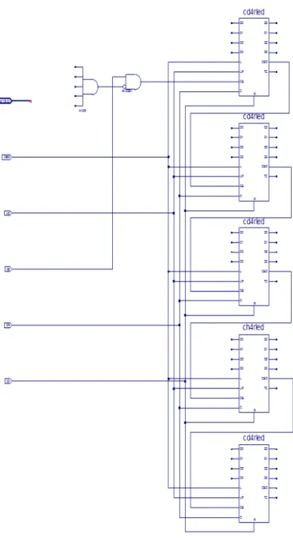
Creating a Schematic-Based Macro . . . 56
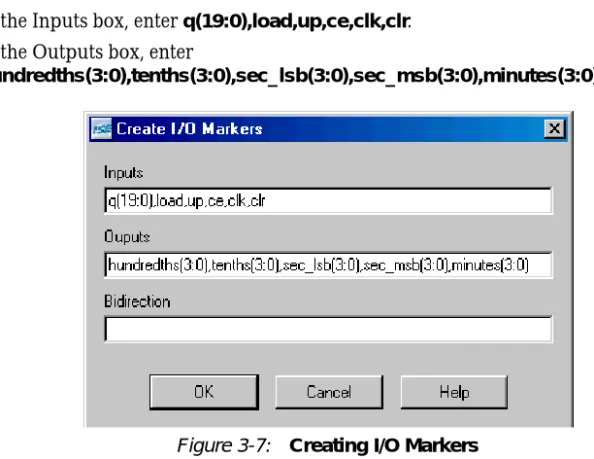
Defining the time_cnt Schematic . . . 57
Adding I/O Markers . . . 58
Adding Schematic Components. . . 58
Correcting Mistakes . . . 61
Drawing Wires . . . 61
Adding Buses . . . 61
Adding Bus Taps . . . 62
Adding Net Names. . . 63
Checking the Schematic . . . 64
Saving the Schematic . . . 65
Creating and Placing the time_cnt Symbol . . . 65
Creating the time_cnt symbol. . . 65
Placing the time_cnt Symbol. . . 65
Creating a CORE Generator Module . . . 66
Creating a CORE Generator Module . . . 66
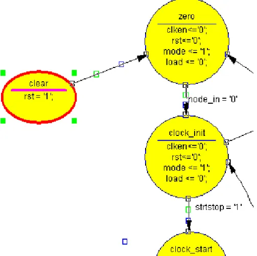
Creating a State Machine Module . . . 68
Adding New States. . . 69
Adding a Transition . . . 70
Adding a State Action. . . 71
Adding a State Machine Reset Condition. . . 73
Creating the State Machine HDL output file. . . 73
Creating the State Machine Symbol . . . 74
Creating a DCM Module . . . 74
Using the Clocking Wizard. . . 74
Creating the dcm1 Symbol . . . 76
Creating an HDL-Based Module . . . 77
Using the New Source Wizard and ISE Text Editor . . . 77
Using the Language Templates. . . 79
Adding a Language Template to Your File. . . 80
Creating the debounce Symbol . . . 81
Placing the statmach, timer_preset, dcm1 and debounce Symbols . . . 81
Changing Instance Names . . . 82
Hierarchy Push/Pop . . . 83
Specifying Device Inputs/Outputs . . . 83
Adding Input Pins . . . 83
Adding I/O Markers and Net Names. . . 84
Assigning Pin Locations . . . 85
Completing the Schematic . . . 85
Chapter 4: Behavioral Simulation
Overview of Behavioral Simulation Flow. . . 89ModelSim PE and SE . . . 89
ModelSim Xilinx Edition . . . 90
ISE Simulator Setup. . . 90
Getting Started. . . 90
Required Files . . . 90
Design Files (VHDL, Verilog, or Schematic). . . 90
Test Bench File . . . 90
Xilinx Simulation Libraries. . . 90
Xilinx Simulation Libraries . . . 90
Updating the Xilinx Simulation Libraries. . . 91
Mapping Simulation Libraries in the Modelsim.ini File. . . 91
Adding an HDL Test Bench . . . 92
Adding Tutorial Test Bench File . . . 92
VHDL Simulation. . . 92
Verilog Simulation . . . 93
Behavioral Simulation Using ModelSim. . . 93
Locating the Simulation Processes . . . 93
Specifying Simulation Properties . . . 94
Performing Simulation . . . 95
Adding Signals . . . 95
Adding Dividers. . . 97
Rerunning Simulation. . . 97
Analyzing the Signals. . . 98
Saving the Simulation . . . 99
Behavioral Simulation Using ISE Simulator . . . 99
Locating the Simulation Processes . . . 99
Specifying Simulation Properties . . . 100
Performing Simulation . . . 101
Adding Signals . . . 101
Rerunning Simulation . . . 102
Analyzing the Signals. . . 103
Creating a Test Bench Waveform Using the Waveform Editor . . . 103
Creating a Test Bench Waveform Source . . . 103
Applying Stimulus . . . 105
Chapter 5: Design Implementation
Overview of Design Implementation . . . 107Getting Started. . . 108
Continuing from Design Entry . . . 108
Starting from Design Implementation . . . 108
Specifying Options . . . 109
Creating Partitions . . . 111
Creating Timing Constraints . . . 112
Translating the Design . . . 113
Using the Constraints Editor . . . 114
Using the Floorplan Editor . . . 118
Mapping the Design . . . 121
Using Timing Analysis to Evaluate Block Delays After Mapping. . . 124
Report Paths in Timing Constraints Option . . . 124
Placing and Routing the Design . . . 126
Using FPGA Editor to Verify the Place and Route. . . 127
Evaluating Post-Layout Timing. . . 129
Changing HDL with Partition . . . 131
Creating Configuration Data . . . 132
Creating a PROM File with iMPACT . . . 134
Command Line Implementation. . . 136
Chapter 6: Timing Simulation
Overview of Timing Simulation Flow . . . 137Getting Started. . . 137
Required Software . . . 137
Required Files . . . 138
Specifying a Simulator . . . 138
Timing Simulation Using ModelSim . . . 138
Specifying Simulation Process Properties . . . 139
Performing Simulation . . . 141
Adding Signals. . . 141
Adding Dividers. . . 143
Rerunning Simulation. . . 144
Analyzing the Signals. . . 144
Saving the Simulation. . . 145
Timing Simulation Using Xilinx ISE Simulator. . . 146
Specifying Simulation Process Properties . . . 146
Performing Simulation . . . 147
Adding Signals. . . 147
Viewing Full Signal Names. . . 149
Rerunning Simulation. . . 149
Analyzing the Signals. . . 150
Chapter 7: iMPACT Tutorial
Device Support . . . 153Download Cable Support . . . 154
Parallel Cable IV . . . 154
Platform Cable USB . . . 154
MultiPRO Cable . . . 154
Configuration Mode Support. . . 154
Getting Started. . . 154
Generating the Configuration Files . . . 154
Connecting the Cable. . . 155
Starting the Software . . . 155
Opening iMPACT from Project Navigator. . . 155
Opening iMPACT stand-alone . . . 155
Creating a iMPACT New Project File . . . 156
Using Boundary Scan Configuration Mode . . . 156
Specifying Boundary Scan Configuration Mode . . . 156
Saving the Project File . . . 159
Editing Preferences . . . 159
Performing Boundary Scan Operations . . . 159
Troubleshooting Boundary Scan Configuration. . . 162
Verifying Cable Connection . . . 162
Verifying Chain Setup . . . 163
Creating an SVF File . . . 164
Setting up Boundary Scan Chain . . . 164
JTAG chain setup for SVF generation. . . 164
Manual JTAG chain setup for SVF generation . . . 164
Writing to the SVF File . . . 165
Stop Writing to the SVF. . . 166
Playing back the SVF or XSVF file . . . 166
Other Configuration Modes. . . 166
Slave Serial Configuration Mode . . . 166
Chapter 1
Overview of ISE and Synthesis Tools
This chapter includes the following sections:
• “Overview of ISE”
• “Using Revision Control Features”
• “Overview of Synthesis Tools”
Overview of ISE
ISE controls all aspects of the design flow. Through the Project Navigator interface, you can access all of the design entry and design implementation tools. You can also access the files and documents associated with your project.
Project Navigator Interface
The Project Navigator Interface is divided into four main subwindows, as seen in
Figure 1-1. On the top left is the Sources window which hierarchically displays the elements included in the project. Beneath the Sources window is the Processes window, which displays available processes for the currently selected source. The third window at the bottom of the Project Navigator is the Transcript window which displays status messages, errors, and warnings and also contains interactive tabs for Tcl scripting and the Find in Files function. The fourth window to the right is a multi-document interface (MDI) window referred to as the Workspace. It enables you to view html reports, ASCII text files, schematics, and simulation waveforms. Each window may be resized, undocked from Project Navigator or moved to a new location within the main Project Navigator window. The default layout can always be restored by selectingView > Restore Default Layout. These windows are discussed in more detail in the following sections.
Sources Window
This window consists of three tabs which provide project and file information for the user. Each tab is discussed in further detail below.
Sources Tab
The Sources tab displays the project name, the specified device, and user documents and design source files associated with the selected Design View. The Design View (“Sources for”) drop-down list at the top of the Sources tab allows you to view only those source files associated with the selected Design View, such as Synthesis/Implementation. In the “Number of” drop-down list, a Resources column and a Preserve Column are available for Designs that use Partitions. The use of partitions is covered inChapter 5, “Design
Implementation”.
Each file in a Design View has an associated icon. The icon indicates the file type (HDL file, schematic, core, or text file, for example). For a complete list of possible source types and their associated icons, see the ISE™ Help. SelectHelp > ISE Help Contents, select the Index tab and search for “Source file types.”
If a file contains lower levels of hierarchy, the icon has a + to the left of the name. HDL files have this + to show the entities (VHDL) or modules (Verilog) within the file. You can expand the hierarchy by clicking the +. You can open a file for editing by double-clicking on the filename.
Snapshots Tab
The Snapshots tab displays all snapshots associated with the project currently open in Project Navigator. A snapshot is a copy of the project including all files in the working directory, and synthesis and simulation sub-directories. A snapshot is stored with the project for which it was taken, and the snapshot can be viewed in the Snapshots tab. You can view the reports, user documents, and source files for all snapshots. All information displayed in the Snapshots tab is read-only. Using snapshots provides an excellent version control system, enabling subteams to do simultaneous development on the same design.
Libraries Tab
The Libraries tab displays all libraries associated with the project open in Project Navigator.
Processes Window
This window contains one default tab called the Processes tab.
Processes Tab
The Processes tab is context sensitive and it changes based upon the source type selected in the Sources tab and the Top-Level Source in your project. From the Processes tab, you can run the functions necessary to define, run and view your design. The Processes tab provides access to the following functions:
• Add an Existing Source • Create New Source • View Design Summary • Design Utilities
Provides access to symbol generation, instantiation templates, viewing command line history, and simulation library compilation.
• User Constraints
Provides access to editing location and timing constraints.
• Synthesis
Provides access to Check Syntax, Synthesis, View RTL or Technology Schematic, and synthesis reports. Available processes vary depending on the synthesis tools you use.
• Implement Design
Provides access to implementation tools, design flow reports, and point tools.
• Generate Programming File
Provides access to configuration tools and bitstream generation.
The Processes tab incorporates automake technology. This enables the user to select any process in the flow and the software automatically runs the processes necessary to get to the desired step. For example, when you run the Implement Design process, Project Navigator also runs the Synthesis process because implementation is dependent on up-to-date synthesis results.
Note: To view a running log of command line arguments used on the current project, expand Design Utilities and select View Command Line Log File. See the Command Line Implementation section ofChapter 5, “Design Implementation” for further details.
Transcript Window
The Transcript window contains five default tabs: Console, Errors, Warnings, Tcl Shell, Find in Files.
• Console
Displays errors, warnings, and information messages. Errors are signified by a red (X) next to the message, while warnings have a yellow exclamation mark (!).
• Warnings
Displays only warning messages. Other console messages are filtered out.
• Errors
Displays only error messages. Other console messages are filtered out.
• Tcl Shell
Is a user interactive console. In addition to displaying errors, warnings and
informational messages, the Tcl Shell allows a user to enter Project Navigator specific Tcl commands. For more information on Tcl commands, see the ISE Help.
• Find in Files
Displays the results of theEdit > Find in Files function.
Error Navigation to Source
You can navigate from a synthesis error or warning message in the Transcript window to the location of the error in a source HDL file. To do so, select the error or warning message, right-click the mouse, and selectGo to Sourcefrom the right-click menu.The HDL source file opens and the cursor moves to the line with the error.
Error Navigation to Answer Record
You can navigate from an error or warning message in the Transcript window to relevant Answer Records on thewww.xilinx.com/support website. To navigate to the Answer Record(s), select the error or warning message, right-click the mouse, and selectGo to Answer Record from the right-click menu. The default web browser opens and displays all Answer Records applicable to this message.
Workspace
Design Summary
The Design Summary lists high-level information about your project, including overview information, a device utilization summary, performance data gathered from the Place & Route (PAR) report, constraints information, and summary information from all reports with links to the individual reports.
Text Editor
Source files and other text documents can be opened in a user designated editor. The editor is determined by the setting found by selectingEdit > Preferences, expand ISE General and clickEditors. The default editor is the ISE Text Editor. ISE Text Editor enables you to edit source files and user documents. You can access the Language Templates, which is a catalog of ABEL, Verilog, VHDL, Tcl and User Constraints File templates that you can use and modify in your own design.
ISE Simulator / Waveform Editor
ISE Simulator / Waveform Editor can be used to create and simulate test bench and test fixture within the Project Navigator framework. Waveform Editor can be used to
graphically enter stimuli and the expected response, then generate a VHDL test bench or Verilog test fixture. For details, refer to“Creating a Test Bench Waveform Using the Waveform Editor” in Chapter 4.
Schematic Editor
The Schematic Editor is integrated in the Project Navigator framework. The Schematic Editor can be used to graphically create and view logical designs.
Using Revision Control Features
Using Snapshots
Snapshots enable you to maintain revision control over the design. A snapshot contains a copy of all of the files in the project directory. See also“Snapshots Tab.”
Creating a Snapshot
To create a snapshot:
1. SelectProject > Take Snapshot.
2. In the Take a Snapshot of the Project dialog box, enter the snapshot name and any comments associated with the snapshot.
The snapshot containing all of the files in the project directory along with project settings is displayed in the Snapshots tab.
Restoring a Snapshot
Since snapshots are read-only, a snapshot must be restored in order to continue work. When you restore a snapshot, it replaces the project in your current session.
To restore a snapshot:
1. In the Snapshots tab, select the snapshot from the drop-down list. 2. SelectProject > Make Snapshot Current.
Before the snapshot replaces the current project, you are given the option to place the current project in a snapshot so that your work is not lost.
Note: Remote sources are copied with the snapshot and placed in a subdirectory named
remote_sources. These files will need to be manually copied to the original location or added to the project again in a new directory
Viewing a Snapshot
The Snapshots tab contains a list of all the snapshots available in the current project. To review a process report or verify process status within a snapshot:
1. Expand the snapshot source tree and select the desired source file. 2. Right-click the mouse over the desired process report.
3. From the menu, selectOpen Without Updating.
Using Project Archives
You can also archive the entire project into a single compressed file. This allows for easier transfer over email and storage of numerous projects in a limited space.
Creating an Archive
To create an archive:
1. SelectProject > Archive.
2. In the Create Zip Archive dialog box, enter the archive name and location.
Note: The archive contains all of the files in the project directory along with project settings. Remote sources are included in the archive under a folder named remote_sources. For more information, see the ISE Help.
Restoring an Archive
You cannot restore an archived file directly into Project Navigator. The compressed file can be extracted with any ZIP utility and you can then open the extracted file in Project Navigator.
Using Export/Import Source Control
You can use this feature to export to and retrieve project files and sources from a “staging area.” The Export/Import processes are typically used in conjunction with a 3rd party source control system but can be used independently as a valid means of backing up a design.
Exporting a Project
To export a project
2. Follow the Export Project Wizard to determine which files to export, where to export the files to, and optionally create a Tcl script that can be used to regenerate the ISE project.
Importing a Project
To import a project
1. SelectProject > Source Control > Import
2. Select the Project File (.ise or Tcl import script) and directory location to import the project file and sources.
Overview of Synthesis Tools
You can synthesize your design using various synthesis tools. The following section lists the supported synthesis tools and includes some process properties information.
Precision Synthesis
This synthesis tool is not part of the ISE package and is not available unless purchased separately. Two commonly used properties are Optimization Goal and Optimization Effort. With these properties you can control the synthesis results for area or speed and the amount of time the synthesizer runs.This synthesis tool is available for both an HDL- and Schematic-based design flow.
Process Properties
Process properties enable you to control the synthesis results of Precision. Most of the commonly used synthesis options available for the Precision stand-alone version are available for Precision synthesis through ISE.
For more information, see the Precision online help.
Synplify/Synplify Pro
This synthesis tool is not part of the ISE package and is not available unless purchased separately. This synthesis tool is available for HDL-based designs, but it is not available for a schematic-based design.
Process Properties
Process properties enable you to control the synthesis results of Synplify/Synplify Pro. Most of the commonly used synthesis options available in the Synplify/Synplify Pro stand-alone version are available for Synplify/Synplify Pro synthesis through ISE. For more information, see the Synplify/Synplify Pro online help.
Figure 1-3: Synplify/Synplify Pro Synthesis Process Properties
Xilinx Synthesis Technology (XST)
This synthesis tool is part of the ISE package and is available for both an HDL- and Schematic-based design flow.
Process Properties
Process properties enable you to control the synthesis results of XST. Two commonly used properties are Optimization Goal and Optimization Effort. With these properties you can control the synthesis results for area or speed, and the amount of time the synthesizer runs. More detailed information is available in the XST User Guide, available in the collection of software manuals. From ISE, selectHelp > Software Manuals, or go on the web at
Chapter 2
HDL-Based Design
This chapter includes the following sections:
• “Overview of HDL-Based Design”
• “Getting Started”
• “Design Description”
• “Design Entry”
• “Synthesizing the Design”
Overview of HDL-Based Design
This chapter guides you through a typical HDL-based design procedure using a design of a runner’s stopwatch. The design example used in this tutorial demonstrates many device features, software features, and design flow practices you can apply to your own design. This design targets a Spartan™-3A device; however, all of the principles and flows taught are applicable to any Xilinx® device family, unless otherwise noted.
The design is composed of HDL elements and two cores. You can synthesize the design using Xilinx Synthesis Technology (XST), Synplify/Synplify Pro, or Precision.
This chapter is the first chapter in the“HDL Design Flow.”After the design is successfully defined, you will perform behavioral simulation (Chapter 4, “Behavioral Simulation”), run implementation with the Xilinx Implementation Tools (Chapter 5, “Design
Implementation”), perform timing simulation (Chapter 6, “Timing Simulation”), and configure and download to the Spartan-3A demo board (Chapter 7, “iMPACT Tutorial”).
Getting Started
The following sections describe the basic requirements for running the tutorial.
Required Software
To perform this tutorial, you must have the following software and software components installed:
• Xilinx Series ISE™ 10.1i
• Spartan-3A libraries and device files
Note: For detailed software installation instructions, refer to the ISE Release Notes and Installation Guide.
This tutorial assumes that the software is installed in the default location c:\xilinx\ISE. If you have installed the software in a different location, substitute your installation path for
c:\xilinx\ISE in the procedures that follow.
Optional Software Requirements
The following third-party synthesis tools are incorporated into this tutorial, and may be used in place of the Xilinx Synthesis Tool (XST):
• Synplicity Synplify/Synplify PRO 8.8.02 (or above)
• Mentor Precision Synthesis 2006a2.7 (or above)
The following third-party simulation tool is optional for this tutorial, and may be used in place of the ISE Simulator:
• ModelSim XE/SE/PE 6.3c or newer
VHDL or Verilog?
This tutorial supports both VHDL and Verilog designs, and applies to both designs simultaneously, noting differences where applicable. You will need to decide which HDL language you would like to work through for the tutorial, and download the appropriate files for that language. XST can synthesize a mixed-language design. However, this tutorial does not go over the mixed language feature.
Installing the Tutorial Project Files
The Stopwatch tutorial projects can be downloaded from
http://www.xilinx.com/support/techsup/tutorials/tutorials10.htm. Download either the VHDL or the Verilog design flow project files.
After you have downloaded the tutorial project files from the Web, unzip the tutorial projects into thec:\xilinx\ISEexamplesdirectory, replacing any existing files in that directory.
When you unzip the tutorial project files intoc:\xilinx\ISEexamples, the directory
wtut_vhd (for a VHDL design flow) orwtut_ver (for a Verilog design flow) is created withinc:\xilinx\ISEexamples, and the tutorial files are copied into the newly-created directory.
The following table lists the locations of tutorial source files.
Note: Do not overwrite any files in the solution directories. Table 2-1: Tutorial Directories
Directory Description
wtut_vhd Incomplete VHDL Source Files
wtut_ver Incomplete Verilog Source Files
wtut_vhd\wtut_vhd_comple ted
Completed VHDL Source Files
wtut_ver\wtut_ver_comple ted
The completed directories contain the finished HDL source files.
This tutorial assumes that the files are unzipped underc:\xilinx\ISEexamples, but you can unzip the source files into any directory with read-write permissions. If you unzip the files into a different location, substitute your project path for
c:\xilinx\ISEexamples in the procedures that follow.
Starting the ISE Software
To start ISE:
Double-click theISE Project Navigator icon on your desktop or selectStart > All Programs > Xilinx ISE Design Suite10.1 > ISE > Project Navigator.
Creating a New Project
Note: Two methods are provided for creating a new project: Using the New Project Wizard and Using a Tcl Script. Use either method provided below.
Creating a New Project: Using the New Project Wizard
1. From Project Navigator, selectFile > New Project. The New Project Wizard appears.
Figure 2-1: Project Navigator Desktop Icon
2. In the Project Location field, browse toc:\xilinx\ISEexamples or to the directory in which you installed the project.
3. Typewtut_vhd orwtut_ver in the Project Name field.
4. Verify that HDL is selected as the Top-Level Source Type and clickNext. The New Project Wizard - Device Properties window appears.
5. Select the following values in the New Project Wizard - Device Properties window:
♦ Product Category:All
♦ Family:Spartan3A and Spartan3AN ♦ Device:XC3S700A
♦ Package:FG484 ♦ Speed:-4
♦ Synthesis Tool:XST (VHDL/Verilog) ♦ Simulator:ISE Simulator (VHDL/Verilog)
♦ Preferred Language:VHDL orVerilogdepending on preference. This will determine the default language for all processes that generate HDL files. 6. ClickNext, thenNext, and then clickAdd Source in the New Project Wizard - Add
Existing Sources window.
7. Browse toc:\xilinx\ISEexamples\wtut_vhd or
c:\xilinx\ISEexamples\wtut_ver.
8. Select the following files (.vhdfiles for VHDL design entry or .v files for Verilog design entry) and clickOpen.
♦ clk_div_262k
♦ lcd_control
♦ statmach
♦ stopwatch
9. ClickNext, thenFinish to complete the New Project Wizard.
10. In the Adding Source Files dialog box, verify that all added HDL files are associated with Synthesis/Imp + Simulation, then clickOK.
Creating a New Project: Using a Tcl Script
1. With Project Navigator open, select the Tcl Shell tab.
2. Change the current working directory to the directory where the tutorial source files were unzipped by typingcd c:/xilinx/ISEexamples/wtut_vhd(VHDL design entry) orcd c:/xilinx/ISEexamples/wtut_ver(Verilog design entry).
3. Run the project creation Tcl script by typingsource create_wtut_vhd.tcl
(VHDL design entry) orsource create_wtut_ver.tcl (Verilog design entry). 4. (VHDL only) Once the project is created and opened, right-click on the device line and
selectProperties...Change the Preferred Language: toVHDL. This will determine the default language for all processes that generate HDL files.
Stopping the Tutorial
You may stop the tutorial at any time and save your work by selectingFile > Save All.
Design Description
The design used in this tutorial is a hierarchical, HDL-based design, which means that the top-level design file is an HDL file that references several other lower-level macros. The lower-level macros are either HDL modules or IP modules.
The design begins as an unfinished design. Throughout the tutorial, you will complete the design by generating some of the modules from scratch and by completing others from existing files. When the design is complete, you will simulate it to verify the design’s functionality.
In the runner’s stopwatch design, there are five external inputs and four external output buses. The system clock is an externally generated signal. The following list summarizes the input and output signals of the design.
Inputs
The following are input signals for the tutorial stopwatch design.
• strtstop
Starts and stops the stopwatch. This is an active low signal which acts like the start/stop button on a runner’s stopwatch.
• reset
Puts the stopwatch in clocking mode and resets the time to 0:00:00.
• clk
Externally generated system clock.
• mode
Toggles between clocking and timer modes. This input is only functional while the clock or timer is not counting.
• lap_load
This is a dual function signal. In clocking mode it displays the current clock value in the ‘Lap’ display area. In timer mode it loads the pre assigned values from the ROM to the timer display when the timer is not counting.
Outputs
The following are outputs signals for the design.
• lcd_e, lcd_rs, lcd_rw
These outputs are the control signals for the LCD display of the Spartan-3A demo board used to display the stopwatch times.
• sf_d[7:0]
Provides the data values for the LCD display.
Functional Blocks
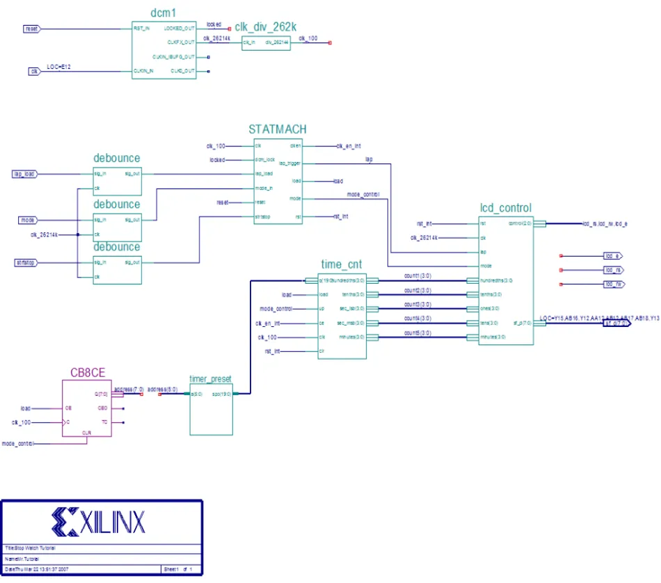
The completed design consists of the following functional blocks.
• clk_div_262k
Macro which divides a clock frequency by 262,144. Converts 26.2144 MHz clock into 100 Hz 50% duty cycle clock.
• dcm1
Clocking Wizard macro with internal feedback, frequency controlled output, and duty-cycle correction. The CLKFX_OUT output converts the 50 MHz clock of the Spartan-3A demo board to 26.2144 MHz.
• debounce
Schematic module implementing a simplistic debounce circuit for the strtstop, mode, and lap_load input signals.
• lcd_control
Module controlling the initialization of and output to the LCD display.
• statmach
State Machine module defined and implemented in State Diagram Editor. Controls the state of the stopwatch.
• timer_preset
CORE Generator™ 64x20 ROM. This macro contains 64 preset times from 0:00:00 to 9:59:99 which can be loaded into the timer.
• time_cnt
Up/down counter module which counts between 0:00:00 to 9:59:99 decimal. This macro has five 4-bit outputs, which represent the digits of the stopwatch time.
Design Entry
For this hierarchical design, you will examine HDL files, correct syntax errors, create an HDL macro, and add a CORE Generator and a Clocking module. You will create and use
each type of design macro. All procedures used in the tutorial can be used later for your own designs.
With thewtut_vhd.ise orwtut_ver.ise project open in Project Navigator, the Sources tab displays all of the source files currently added to the project, with the associated entity or module names (seeFigure 2-4). In the current project,time_cnt is instantiated, but the associated entity or module is not defined in the project.
Instantiated components with no entity or module declaration are displayed with a red question mark.
Adding Source Files
HDL files must be added to the project before they can be synthesized. Three HDL files have already been added to this project. An additional file must be added.
1. SelectProject > Add Source.
2. Selecttime_cnt.vhd ortime_cnt.v from the project directory and clickOpen. 3. In the Adding Source Files dialog box,verify thattime_cnt is associated with
Synthesis/Imp + Simulation and click OK.
Note: Alternatively, the time_cnt.vhd file could be added to the project by entering the following command in the Tcl Shell tab.
xfile add time_cnt.vhd
The red question-mark (?) for time_cnt should change to show the VHD file icon.
Each source Design unit is represented under the sources tab using the following syntax: <instance name> - <entity name> - <architecture name> - (<file name>).
Figure 2-4: Sources Tab Showing Completed Design
Checking the Syntax
To check the syntax of source files:
1. Selectstopwatch.vhd orstopwatch.v in the Sources tab.
When you select the HDL file, the Processes tab displays all processes available for this file.
2. In the Processes tab, click the+ next to Synthesize to expand the process hierarchy. 3. Double-clickCheck Syntaxin the Synthesize hierarchy.
Note: Check Syntax is not available when Synplify is selected as the synthesis tool.
Correcting HDL Errors
The time_cnt module contains a syntax error that must be corrected. The red “x” beside the Check Syntax process indicates an error was found during the analysis. In the Console tab of the Transcript window, Project Navigator reports errors with a red (X) and warnings with a yellow (!).
To display the error in the source file:
1. Click the file name in the error message in the Console or Errors tab. The source code comes up in the main display tab.
2. Correct any errors in the HDL source file. The comments next to the error explain this simple fix.
3. SelectFile > Save to save the file.
4. Re-analyze the file by selecting the HDL file and double-clickingCheck Syntax.
Creating an HDL-Based Module
Next you will create a module from HDL code. With ISE, you can easily create modules from HDL code using the ISE Text Editor. The HDL code is then connected to your top-level HDL design through instantiation and is compiled with the rest of the design. You will author a new HDL module. This macro will be used to debounce the strtstop, mode and lap_load inputs.
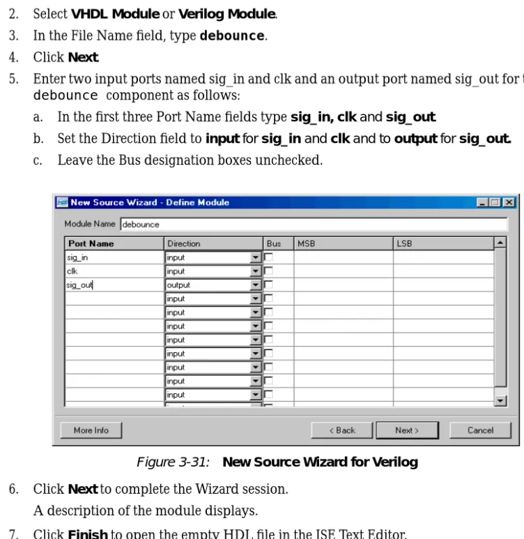
Using the New Source Wizard and ISE Text Editor
In this section, you create a file using the New Source wizard, specifying the name and ports of the component. The resulting HDL file is then modified in the ISE Text Editor. To create the source file:
1. SelectProject > New Source.
The dialog box New Source Wizard opens in which you specify the type of source you want to create.
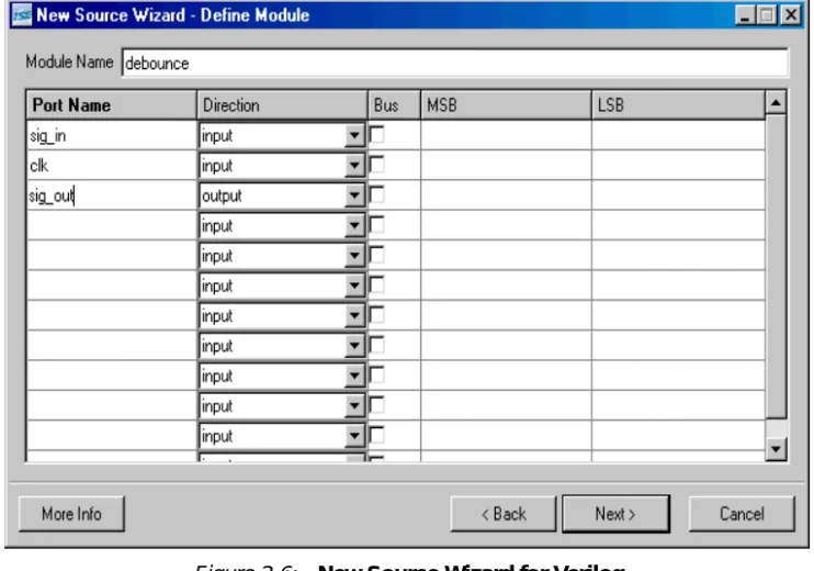
2. SelectVHDL Module orVerilog Module. 3. In the File Name field, typedebounce. 4. ClickNext.
5. Enter two input ports named sig_in and clk and an output port named sig_out for the
debounce component in this way:
b. Set the Direction field toinput for sig_in and clk and to output for sig_out.
c. Leave the Bus designation boxes unchecked.
6. ClickNext to complete the Wizard session. A description of the module displays.
7. ClickFinish to open the empty HDL file in the ISE Text Editor.
The VHDL file is displayed inFigure 2-7. The Verilog HDL file is displayed inFigure 2-8.
In the ISE Text Editor, the ports are already declared in the HDL file, and some of the basic file structure is already in place. Keywords are displayed in blue, comments in green, and values are black. The file is color-coded to enhance readability and help you recognize typographical errors.
Figure 2-7: VHDL File in ISE Text Editor
Using the Language Templates
The ISE Language Templates include HDL constructs and synthesis templates which represent commonly used logic components, such as counters, D flip-flops, multiplexers, and primitives. You will use the Debounce Circuit template for this exercise.
Note: You can add your own templates to the Language Templates for components or constructs that you use often.
To invoke the Language Templates and select the template for this tutorial: 1. From Project Navigator, selectEdit > Language Templates.
Each HDL language in the Language Templates is divided into five sections: Common Constructs, Device Primitive Instantiation, Simulation Constructs, Synthesis
Constructs and User Templates. To expand the view of any of these sections, click the
+next to the section. Click any of the listed templates to view the template contents in the right pane.
2. Under either the VHDL or Verilog hierarchy, expand the Synthesis Constructs hierarchy, expand the Coding Examples hierarchy, expand the Misc hierarchy, and select the template called [One-shot,] Debounce Circuit. Use the appropriate template for the language you are using.
Adding a Language Template to Your File
You will now use the drag and drop method for adding templates to your HDL file. Refer to “Working with Language Templates” in the ISE Help for additional usability options. To add the template to your HDL file using the drag and drop method:
1. SelectWindow > Tile Vertically to show both the HDL file and the Language Templates window.
2. Click and drag theDebounce Circuitname from the Language Template topology into thedebounce.vhd file under the architecturebegin statement, or into the
debounce.v file under themodule and pin declarations. 3. Close the Language Templates window.
4. (Verilog only) Complete the Verilog module by doing the following:
a. Remove the reset logic (not used in this design) by deleting the three lines beginning with if and ending with else.
b. Change <reg_name> to q in all six locations.
c. Change <clock> to clk; <input> to sig_in; and <output> to sig_out. 5. (VHDL only) Complete the VHDL module by doing the following:
a. Move the line beginning with the word signal so that it is between the architecture and begin keywords.
b. Remove the reset logic (not used in this design) by deleting the five lines beginning with if (<reset>... and ending with else and delete one of the end if; lines.
c. UseEdit > Replace to change <clock> to clk; D_IN to sig_in; and Q_OUT to
sig_out.
You now have complete and functional HDL code. 6. Save the file by selectingFile > Save.
7. Select one of thedebounce instances in the Sources tab. 8. In the Processes tab, double-clickCheck Syntax. 9. Close the ISE Text Editor.
Creating a CORE Generator Module
CORE Generator is a graphical interactive design tool that enables you to create high-level modules such as memory elements, math functions and communications and IO interface cores. You can customize and pre-optimize the modules to take advantage of the inherent architectural features of the Xilinx FPGA architectures, such as Fast Carry Logic, SRL16s, and distributed and block RAM.
In this section, you will create a CORE Generator module called timer_preset. The module will be used to store a set of 64 values to load into the timer.
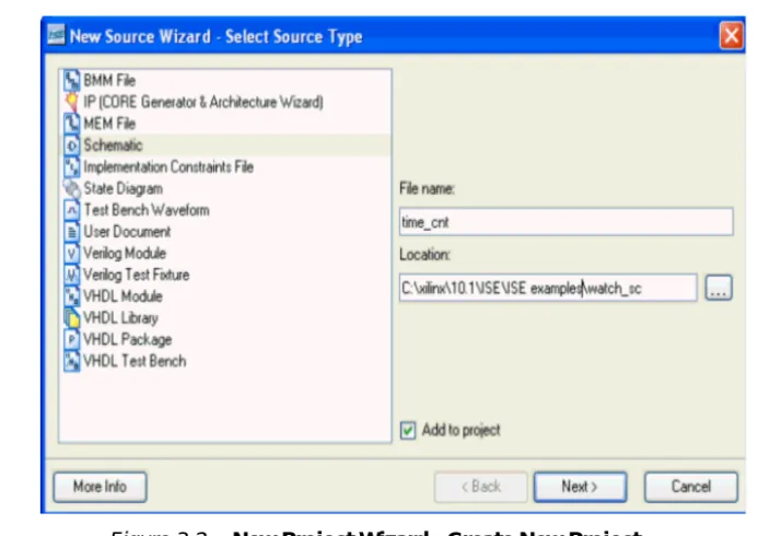
Creating a CORE Generator Module
To create a CORE Generator module:
1. In Project Navigator, selectProject > New Source. 2. SelectIP (Coregen & Architecture Wizard). 3. Typetimer_preset in the File name field. 4. ClickNext.
5. Double-clickMemories & Storage Elements, then double-clickRAMs & ROMs. 6. SelectDistributed Memory Generator, then clickNext and clickFinish to open the
Distributed Memory Generator customization GUI. This customization GUI enables you to customize the memory to the design specifications.
7. Fill in the Distributed Memory Generator customization GUI with the following settings:
♦ Component Name:timer_preset -Defines the name of the module.
♦ Depth:64 - Defines the number of values to be stored
♦ Data Width:20 -Defines the width of the output bus.
♦ Memory Type:ROM ♦ ClickNext.
♦ Coefficients File: Click theBrowse button and select definition1_times.coe.
8. Check that only the following pins are used (used pins are highlighted on the symbol on the left side of the customization GUI):
♦ a[5:0] ♦ spo[19:0]
9. ClickFinish.
The module is created and automatically added to the project library.
Note: A number of files are added to the project directory. Some of these files are: ♦ timer_preset.vho or timer_preset.veo
These are the instantiation templates used to incorporate the CORE Generator module into your source HDL.
♦ timer_preset.vhd or timer_preset.v
These are HDL wrapper files for the core and are used only for simulation.
♦ timer_preset.edn
This file is the netlist that is used during the Translate phase of implementation.
♦ timer_preset.xco
This file stores the configuration information for the timer_preset module and is used as a project source.
♦ timer_preset.mif
This file provides the initialization values of the ROM for simulation.
Instantiating the CORE Generator Module in the HDL Code
Next, instantiate the CORE Generator module in the HDL code using either a VHDL flow or a Verilog flow.
VHDL Flow
To instantiate the CORE Generator module using a VHDL flow:
1. In Project Navigator, double-clickstopwatch.vhdto open the file in ISE Text Editor. 2. Place your cursor after the line that states:
-- Insert CORE Generator ROM component declaration here
3. SelectEdit >Insert File,then selecttimer_preset.vho and clickOpen. The VHDL template file for the CORE Generator instantiation is inserted.
4. Highlight the inserted code from
-- Begin Cut here for INSTANTIATION Template
----to
--INST_TAG_END - END INSTANTIATION Template
---5. SelectEdit > Cut.
6. Place the cursor after the line that states:
--Insert CORE Generator ROM Instantiation here
7. SelectEdit > Paste to place the core instantiation.
8. Change the instance name fromyour_instance_name tot_preset.
9. Edit this instantiated code to connect the signals in the Stopwatch design to the ports of the CORE Generator module as shown inFigure 2-12.
Figure 2-11: VHDL Component Declaration for CORE Generator Module
10. The inserted code oftimer_preset.vho contains several lines of commented text for instruction and legal documentation. Delete these commented lines if desired. 11. Save the design usingFile > Save, and close the ISE Text Editor.
Verilog Flow
To instantiate the CORE Generator module using a Verilog flow:
1. In Project Navigator, double-clickstopwatch.vto open the file in the ISE Text Editor. 2. Place your cursor after the line that states:
//Place the Coregen module instantiation for timer_preset here
3. SelectEdit > Insert File,and selecttimer_preset.veo.
4. The inserted code oftimer_preset.veo contains several lines of commented text for instruction and legal documentation. Delete these commented lines if desired. 5. Change the instance name fromYourInstanceName tot_preset.
6. Edit this code to connect the signals in the Stopwatch design to the ports of the CORE Generator module as shown inFigure 2-13.
7. Save the design usingFile > Save and closestopwatch.v in the ISE Text Editor.
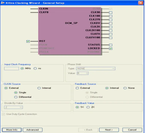
Creating a DCM Module
The Clocking Wizard, a part of the Xilinx Architecture Wizard, enables you to graphically select Digital Clock Manager (DCM) features that you wish to use. In this section you will create a basic DCM module with CLK0 feedback and duty-cycle correction.
Using the Clocking Wizard
To create the dcm1 module:
1. In Project Navigator, selectProject > New Source.
2. In the New Source dialog box, selectIP (CoreGen & Architecture Wizard)source and typedcm1 for the file name.
3. ClickNext.
4. In the Select IP dialog box, selectFPGA Features and Design > Clocking > Spartan-3E, Spartan-3A > Single DCM SP.
Figure 2-14: Selecting Single DCM IP Type
5. ClickNext,then Finish.The Clocking Wizard is launched. 6. Verify thatRST,CLK0 andLOCKED ports are selected. 7. SelectCLKFX port.
8. Type50 and selectMHz for the Input Clock Frequency. 9. Verify the following settings:
♦ Phase Shift:NONE
♦ CLKIN Source:External,Single ♦ Feedback Source:Internal ♦ Feedback Value:1X
♦ Use Duty Cycle Correction: Selected 10. Click theAdvanced button.
11. SelectWait for DCM lock before DONE Signal goes high. 12. ClickOK.
13. ClickNext, and then clickNextagain.
14. SelectUse output frequency and type26.2144 in the box and selectMHz.
15. ClickNext, and then clickFinish.
Thedcm1.xaw file is added to the list of project source files in the Sources tab.
26.2144Mhz
Instantiating the dcm1 Macro - VHDL Design
Next, you will instantiate the dcm1 macro for your VHDL or Verilog design. To instantiate the dcm1 macro for the VHDL design:
1. In Project Navigator, in the Sources tab, selectdcm1.xaw.
2. In the Processes tab, right-clickView HDL Instantiation Template and select
Properties.
3. ChooseVHDL for the HDL Instantiation Template Target Language value and click
OK.
4. In the Processes tab, double-clickView HDL Instantiation Template.
5. Highlight the component declaration template in the newly opened HDL Instantiation Template (dcm1.vhi), shown below.
6. SelectEdit > Copy.
7. Place the cursor in the stopwatch.vhd file in a section labeled
-- Insert dcm1 component declaration here.
8. SelectEdit > Paste to paste the component declaration.
9. Highlight the instantiation template in the newly opened HDL Instantiation Template, shown below.
10. SelectEdit > Copy.
11. Place the cursor in thestopwatch.vhd file below the line labeled
“-- Insert dcm1 instantiation here”.
Figure 2-15: VHDL DCM Component Declaration
12. SelectEdit > Paste to paste the instantiation template. 13. Make the necessary changes as shown in the figure below.
14. SelectFile > Save to save thestopwatch.vhd file.
Instantiating the dcm1 Macro - Verilog
To instantiate the dcm1 macro for your Verilog design: 1. In Project Navigator, in the Sources tab, selectdcm1.xaw.
2. In the Processes tab, double-clickView HDL Instantiation Template. 3. From the newly opened HDL Instantiation Template (dcm1.tfi), copy the
instantiation template, shown below.
4. Paste the instantiation template into the section instopwatch.v labeled
//Insert dcm1 instantiation here.
5. Make the necessary changes as shown in the figure below.
Figure 2-19: Verilog Instantiation for dcm1
6. SelectFile > Save to save thestopwatch.v file.
Figure 2-17: VHDL Instantiation for dcm1
Synthesizing the Design
So far you have been using XST (the Xilinx synthesis tool) for syntax checking. Next, you will synthesize the design using either XST, Synplify/Synplify Pro or Precision. The synthesis tool uses the design’s HDL code and generates a supported netlist type (EDIF or NGC) for the Xilinx implementation tools. The synthesis tool performs three general steps (although all synthesis tools further break down these general steps) to create the netlist:
• Analyze / Check Syntax
Checks the syntax of the source code.
• Compile
Translates and optimizes the HDL code into a set of components that the synthesis tool can recognize.
• Map
Translates the components from the compile stage into the target technology’s primitive components.
The synthesis tool can be changed at any time during the design flow. To change the synthesis tool:
1. Select the targeted part in the Sources tab. 2. SelectSource > Properties.
3. In the Project Properties dialog box, click on the Synthesis Tool value and use the pull-down arrow to select the desired synthesis tool from the list.
Note: If you do not see your synthesis tool among the options in the list, you may not have the software installed or may not have it configured in ISE. The Synthesis tools are configured in the Preferences dialog box (Edit>Preferences, expand ISE General, then click Integrated Tools).
Changing the design flow results in the deletion of implementation data. You have not yet created any implementation data in this tutorial. For projects that contain implementation data, Xilinx recommends that you take a snapshot of the project before changing the
synthesis tool to preserve this data. For more information about taking a snapshot, see
“Creating a Snapshot” in Chapter 1.
A summary of available synthesis tools is available in“Overview of Synthesis Tools” in Chapter 1
Read the section for your synthesis tool:
• “Synthesizing the Design using XST”
• “Synthesizing the Design using Synplify/Synplify Pro”
• “Synthesizing the Design Using Precision Synthesis”
Synthesizing the Design using XST
Now that you have created and analyzed the design, the next step is to synthesize the design. During synthesis, the HDL files are translated into gates and optimized for the target architecture.
Processes available for synthesis using XST are as follows:
• View Synthesis Report
Gives a synthesis mapping and timing summary as well as a list of optimizations that took place.
• View RTL Schematic
Generates a schematic view of your RTL netlist.
• View Technology Schematic
Generates a schematic view of your Technology netlist.
• Check Syntax
Verifies that the HDL code is entered properly.
• Generate Post-Synthesis Simulation Model
Creates HDL simulation models based on the synthesis netlist.
Entering Constraints
XST supports a User Constraint File (UCF) style syntax to define synthesis and timing constraints. This format is called the Xilinx Constraint File (XCF), and the file has an .xcf file extension. XST uses the .xcf extension to determine if the file is a constraints file. To create a new Xilinx Constraint File:
1. SelectProject > Add Source.
2. In the Add Existing Sources dialog box, change the Files of type: to ‘All Files (*.*) and then select and addstopwatch.xcf.
3. Notice that stopwatch.xcf is added as a User Document.
Note: In place of the three steps above, you may add the .xcf file through the Tcl Shell, using the following command and then selectingView > Refresh.
xfile add stopwatch.xcf
4. Double-clickstopwatch.xcf to open the file in the ISE Text Editor. 5. The following constraints should exist in thestopwatch.xcf file:
TIMESPEC “TS_CLK”=PERIOD “CLK_GROUP” 20 ns; BEGIN MODEL stopwatch
NET "sf_d<7>" LOC = "Y15"; NET "sf_d<6>" LOC = "AB16"; NET "sf_d<5>" LOC = "Y16"; NET "sf_d<4>" LOC = "AA12"; NET "sf_d<3>" LOC = "AB12"; NET "sf_d<2>" LOC = "AB17"; NET "sf_d<1>" LOC = "AB18"; NET "sf_d<0>" LOC = "Y13"; END;
6. Closestopwatch.xcf.
Note: For more constraint options in the implementation tools, see“Using the Constraints Editor” and“Using the Floorplan Editor” inChapter 5, “Design Implementation.”
Entering Synthesis Options
Synthesis options enable you to modify the behavior of the synthesis tool to make optimizations according to the needs of the design. One commonly used option is to control synthesis to make optimizations based on area or speed. Other options include controlling the maximum fanout of a flip-flop output or setting the desired frequency of the design.
To enter synthesis options:
1. Selectstopwatch.vhd (orstopwatch.v) in the Sources tab.
2. In the Processes tab, right-click theSynthesize process and selectProperties. 3. Under the Synthesis Options tab, click in the Synthesis Constraints File property
field and enterstopwatch.xcf.
4. Check theWrite Timing Constraints box. 5. ClickOK.
Synthesizing the Design
Now you are ready to synthesize your design. To take the HDL code and generate a compatible netlist:
1. Selectstopwatch.vhd (orstopwatch.v).
2. Double-click theSynthesize process in the Processes tab.
The RTL / Technology Viewer
XST can generate a schematic representation of the HDL code that you have entered. A schematic view of the code helps you analyze your design by displaying a graphical connection between the various components that XST has inferred. There are two forms of the schematic representation:
• RTL View - Pre-optimization of the HDL code.
• Technology View - Post-synthesis view of the HDL design mapped to the target technology.
1. In the Processes tab, click the+ next to Synthesize to expand the process hierarchy. 2. Double-clickView RTL Schematicor View Technology Schematic.
The RTL Viewer displays the top level schematic symbol for the design. Double-click on the symbol to push into the schematic and view the various design elements and connectivity. Right-click the schematic to view the various operations that can be performed in the schematic viewer.
You have completed XST synthesis. An NGC file now exists for the Stopwatch design. To continue with the HDL flow:
• Go toChapter 4, “Behavioral Simulation,” to perform a pre-synthesis simulation of this design.
OR
• Proceed toChapter 5, “Design Implementation,” to place and route the design.
Note: For more information about XST constraints, options, reports, or running XST from the command line, see the XST User Guide. This guide is available in the collection of software manuals and is accessible from ISE by selecting Help>Software Manuals, or from the web at
http://toolbox.xilinx.com/docsan/xilinx10/books/manuals.pdf
Synthesizing the Design using Synplify/Synplify Pro
Now that you have entered and analyzed the design, the next step is to synthesize the design. In this step, the HDL files are translated into gates and optimized to the target
architecture. To access Synplify’s RTL viewer and constraints editor you must run Synplify outside of ISE.
To synthesize the design, set the global synthesis options: 1. Selectstopwatch.vhd (orstopwatch.v).
2. In the Processes tab, right-click theSynthesize process and selectProperties. 3. Check theWrite Vendor Constraint File box.
4. ClickOK to accept these values.
5. Double-click theSynthesize process to run synthesis.
Note: This step can also be done by selectingstopwatch.vhd (orstopwatch.v), clicking Synthesize in the Processes tab, and selecting Process>Run.
Processes available in Synplify and Synplify Pro synthesis include:
• View Synthesis Report
Lists the synthesis optimizations that were performed on the design and gives a brief timing and mapping report.
• View RTL Schematic
Accessible from the Launch Tools hierarchy, this process displays Synplify or Synplify Pro with a schematic view of your HDL code
• View Technology Schematic
Accessible from the Launch Tools hierarchy, this process displays Synplify or Synplify Pro with a schematic view of your HDL code mapped to the primitives associated with the target technology.
Examining Synthesis Results
To view overall synthesis results, double-clickView Synthesis Report under the
Synthesize process. The report consists of the following four sections:
• “Compiler Report”
• “Mapper Report”
• “Timing Report”
• “Resource Utilization”
Compiler Report
The compiler report lists each HDL file that was compiled, names which file is the top level, and displays the syntax checking result for each file that was compiled. The report also lists FSM extractions, inferred memory, warnings on latches, unused ports, and removal of redundant logic.
Note: Black boxes (modules not read into a design environment) are always noted as unbound in the Synplify reports. As long as the underlying netlist (.ngo, .ngc or .edn) for a black box exists in the project directory, the implementation tools merge the netlist into the design during the Translate phase.
Mapper Report
The mapper report lists the constraint files used, the target technology, and attributes set in the design. The report lists the mapping results of flattened instances, extracted counters, optimized flip-flops, clock and buffered nets that were created, and how FSMs were coded.
Timing Report
The timing report section provides detailed information on the constraints that you entered and on delays on parts of the design that had no constraints. The delay values are based on wireload models and are considered preliminary. Consult the post-place and route timing reports discussed inChapter 5, “Design Implementation,” for the most accurate delay information.
Resource Utilization
This section of the report lists all of the resources that Synplify uses for the given target technology.
You have now completed Synplify synthesis. At this point, a netlist EDN file exists for the Stopwatch design.
To continue with the HDL flow:
• Go toChapter 4, “Behavioral Simulation,” to perform a pre-synthesis simulation of this design.
OR
• Proceed toChapter 5, “Design Implementation,” to place and route the design.
Synthesizing the Design Using Precision Synthesis
Now that you have entered and analyzed the design, the next step is to synthesize the design. In this step, the HDL files are translated into gates and optimized to the target architecture.
Processes available for Precision Synthesis include:
• Check Syntax
Checks the syntax of the HDL code.
• View Log File
Lists the synthesis optimizations that were performed on the design and gives a brief timing and mapping report.
• View RTL Schematic
Accessible from the Launch Tools hierarchy, this process displays Precision with a schematic-like view of your HDL code