IMPORTANT SAFETY INSTRUCTIONS
WARNING!
Basic precautions should always be observed regarding
the installation and the operation of a whirlpool system,
including the following:
1. READ AND FOLLOW ALL INSTRUCTIONS.
2.
DANGER: To reduce the risk of injury, DO NOT allow children to use or
operate the whirlpool unless closely supervised by an adult at all
times.
3.
Use this unit only for its intended purpose as described in this
publica-tion. DO NOT use attachments not recommended by the
manufac-turer.
4.
NEVER drop or insert any object into any opening.
5.
DO NOT operate the whirlpool without the guard(s) (suction covers)
installed over the suction fitting(s).
6.
The whirlpool system can only be connected to an electric supply
that is protected by a ground-fault-circuit-interrupter (GFCI). The
GFCI should be provided by the installer and tested on a routine
basis.
❏
To test the GFCI, push the test button. The GFCI
should interrupt power.
❏
Push the reset button. Power should be restored.
If the GFCI fails to operate in this manner, there is a ground current
flowing, indicating the possibility of an electric shock. DO NOT USE
THE WHIRLPOOL. DISCONNECT THE WHIRLPOOL SYSTEM, and have
the problem corrected by a qualified service representative before
continuing usage.
7.
A green colored terminal (or a wire connector marked "G", "GR",
"Ground", or "Grounding") is provided inside the terminal
compart-ment of the pump. To reduce the risk of electrical shock, connect
this terminal to the grounding terminal in the electrical service supply
panel using a continuous green insulated copper wire equivalent in
size to the service conductors supplying this equipment, but no
smaller than No.12 AWG (3.3 mm).
8.
A pressure wire connector on the pump, near the terminal
compart-ment, is provided to permit connection of a No. 8 AWG (8.4 mm
2)
solid copper bonding conductor between the system and all other
electrical equipment and exposed metal in the vicinity, as needed
to comply with local requirements.
9. SAVE THESE INSTRUCTIONS.
Bodywrap Whirlpool SystemBodywrap whirlpool systems are offered on numerous MAAX Aker models of various sizes, shapes and surface materials. Depending on the model selected, the unit is equipped with a complete multi-jet factory installed and tested system designed for personal usage in a permanent installation. (Refer to specific model for exact features.)
These guidelines are recommended by MAAX Aker for the proper assembly and operation of the whirlpool system. A careful review of these procedures (and any referenced publications) before starting is important in avoiding unnecessary problems resulting in an improper assembly or operation. NOTE: All drawings in this publication are typical and may appear different than the actual items
WARNING!
NEVER LIFT OR HANDLE WHIRLPOOL BY SYSTEM PIPING AT ANY TIME. LIFTING THE UNIT BY THE PIPING CAN
CAUSE SYSTEM DAMAGE.
SPECIAL NOTE TO INSTALLER
✱It is the sole responsibility of the installer to determine, prior to installa-tion, the requirements necessary for compliance with all codes involving the unit and the installation!
✱All paperwork packaged with the unit and any associated options or accesso-ries should be saved and presented to the homeowner upon completion of the installation!
✱All published unit dimensions are for reference only. Any critical dimensions required for installation should be taken directly from the unit being installed!
✱Any independent changes made to the whirlpool system (or unit) beyond those required for normal installation can void all warranties! (Refer to warranties for further information.
Inspection Guidelines
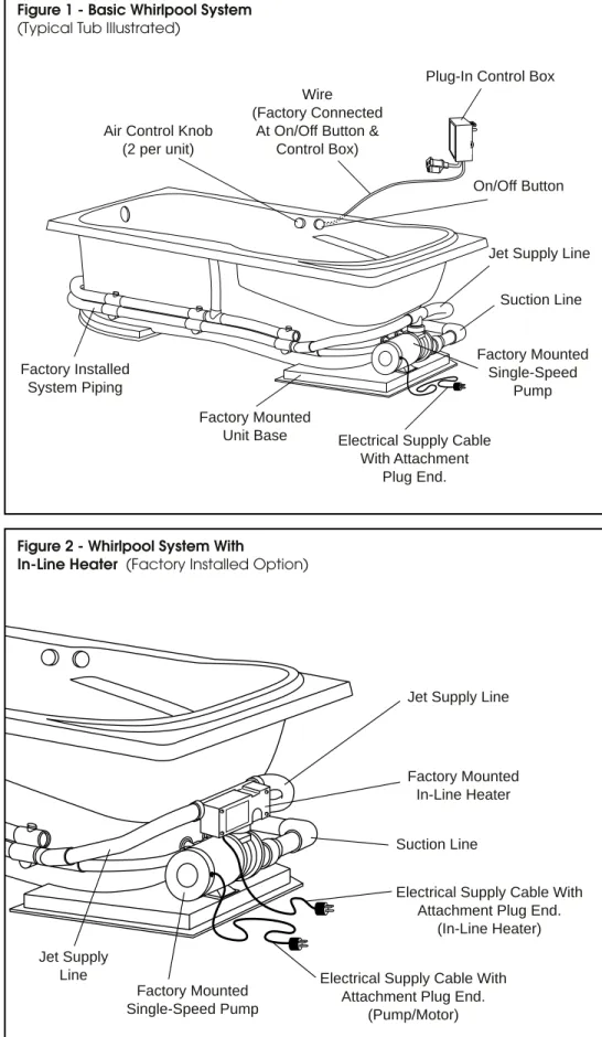
A careful check of the whirlpool system should be conducted upon receipt of the unit. The basic whirlpool configuration is shown in Figure 1. A system with an in-line heater is shown in Figure 2. If the unit has a factory-fitted:
❏alternate pump location, refer to the Supplemental Assembly information packaged with the acces-sory items for additional item checks before continuing. Notify your supplier immediately if any questions or prob-lems are encountered during this process.
DO NOT INSTALL UNIT WITHOUT FIRST ADDRESSING QUESTIONS WHICH ARISE DURING
THE INSPECTION! Basic Whirlpool System Check
✔Check wire lead at on/off button and at control box for secure attachment.
✔Check system to ensure all trim is in place and for finish ordered.
Whirlpool System with Mounted In-Line Heater Check
✔Check for factory installed in-line heater option mounted on pump.
Basic Module Check
An individual check list is included in the installation guidelines packaged with the module. Refer to the listed publica-tion for further informapublica-tion before continuing.
Installation Guidelines
Framing and Installation Requirements
Framing and dimensional requirements for the module are included in the installation guidelines packaged with the basic unit. Refer to the unit installa-tion guidelines for further informainstalla-tion before continuing.
WARNING!
ADEQUATE ACCESS MUST BE PROVIDED AT THE PUMP LOCATION. The basic whirlpool system is produced with the pump secured to the unit base and with the complete system as-sembled at the factory.
Figure 1 - Basic Whirlpool System
(Typical Tub Illustrated)
On/Off Button Air Control Knob
(2 per unit)
Suction Line
Factory Installed System Piping
Jet Supply Line
Factory Mounted Single-Speed
Pump Factory Mounted
Unit Base Electrical Supply Cable With Attachment
Plug End.
Plug-In Control Box Wire
(Factory Connected At On/Off Button &
Control Box)
Figure 2 - Whirlpool System With
In-Line Heater (Factory Installed Option)
Factory Mounted Single-Speed Pump
Factory Mounted In-Line Heater Jet Supply Line
Suction Line
Electrical Supply Cable With Attachment Plug End.
(In-Line Heater)
Electrical Supply Cable With Attachment Plug End.
(Pump/Motor) Jet Supply
If the unit has a factory-fitted:
❏alternate pump location,
additional on-site assembly will be required. Refer to the Supplemental Assembly information packaged with accessory item(s) before continuing.
Electrical Service and Connections
When providing electrical service, basic precautions should be observed, including the following:
✱All wiring should be done by a licensed electrician in accordance with all applicable local and national codes.
✱The system must be connected to a dedicated circuit(s) protected by a ground-fault-circuit-interrupter(s), (GFCI). (Installer supplied)
✱Properly ground the system.
WARNING!
RISK OF ELECTRICAL SHOCK! MAKE SURE POWER IS OFF WHEN WIRING THE WHIRLPOOL SYSTEM. System Pump Wiring
The field electrical connection is a single dedicated service line, protected by a ground-fault-circuit-interrupter (GFCI), running from the main panel to an independently mounted junction box with a 20 amp electrical recep-tacle and a 20 amp breaker. Junction box mounting and all field electrical connections must be in compliance with applicable codes for the installa-tion site.
Each whirlpool is supplied with a special whirlpool system control box. The control box includes a wire lead that is secured to the on/off control button and attached to the control box. A single electrical supply cable with an attachment plug, extending from the wiring compartment on the pump/ motor, fitted through a strain relief fitting, is also supplied as a standard component of the system. All internal pump/motor wiring connections have been completed by the pump/motor manufacturer.
The control box is plugged into the GFCI circuit receptacle and the pump supply cable plugged into the pigtail on the bottom of the control box as shown in Figure 3.
In-Line Heater Wiring
A single electrical supply cable with an attachment plug, extending from the wiring compartment on the in-line heater, is supplied as a standard component of the in-line heater. All internal wiring connections have been completed by the heater manufac-turer. The field electrical connection is a single dedicated service line, (inde-pendent of the pump/motor circuit), protected by a ground-fault-circuit-interrupter (GCFI), running from the main panel to an independently mounted junction box with an appropri-ate electrical receptacle for the in-line heater attachment plug. Breaker size, junction box mounting, receptacle selection and all field electrical con-nections must be in compliance with applicable codes for the installation site. No control box is necessary for the in-line heater system. All controls are housed internally in the heater.
Whirlpool System Field Testing ATTENTION INSTALLER! WHIRLPOOL SYSTEM MUST BE FIELD TESTED FOR LEAKS BEFORE FRAMING IS
COVERED OR THE UNIT ENCLOSED. After completing all water supply, drain and electrical connections, use the following procedure to test the system and all fittings for leaks.
Step 1: Thoroughly clean tub of all debris which could damage the
system, including small particles which could lodge in the jets or the pump.
Step 2: Close the drain and fill tub to the top of trim ring on the highest jet.
Step 3: Start whirlpool and operate continuously for 20 minutes. (1 complete timer cycle.) During the cycle, adjust the air controls (Figure 5) and the Selectaflow control (Figure 10) through the complete range, and check each jet for proper operation. After carefully checking each jet, fully close the air controls, Selectaflow, and foot and side jets (see Figures 8 & 9), and continue running.
Step 4: After the timer cycle, inspect all fittings and connections for leaks before draining.
WARNING! AVOID OPERATING THE WHIRLPOOL SYSTEM WITHOUT ADEQUATE WATER IN THE TUB.
Whirlpool System Care and Cleaning Through routine use, the whirlpool system can collect residues from soap, bath additives and natural body oils.
WARNING!! Do Not Pull On Wire Lead
Attached To Box
GFCI Protected, 20 Amp Whirlpool Circuit
Whirlpool System Control Box
To On / Off Control Button Mounted On Tub Figure 3 - Control Box Connections
Pump / Motor Electrical Plug
Additional deposits can also collect from minerals or particles found in the water.
WARNING!
NEVER USE ABRASIVE MATERIALS, NOR ABRASIVE CLEANERS ON THE WHIRLPOOL TRIM. (JETS, AIR CONTROLS
AND SUCTION COVERS) EXTREME CAUTION is urged regarding the use of any cleaner, acid or solvent on the whirlpool system trim.
Only use MILD liquid detergent on trim! Incorrect cleaning materials can
damage finish on trim, drain/overflow and supply valves. READ AND FOLLOW ALL PACKAGE
LABELS AND INSTRUCTIONS! The following procedure is recom-mended to remove most deposits and avoid major accumulations inside the system piping. The actual schedule for cleaning will depend on system usage and water quality, but should not exceed 90 days.
Step 1: Fill tub to the top of the trim ring on the highest jet with luke-warm water. (Figure 4)
Step 2: Add 1 cup low-sudsing, auto-matic dishwasher detergent and run the whirlpool system for 20 minutes. (1 complete timer cycle.)
Step 3: Drain tub, refill with clean water and operate the system for 20-minutes (1 complete timer cycle) to rinse. (Rinse thor-oughly.)
Occasionally sanitize the system by following the cleaning procedure above, but substitute 1 cup of house-hold bleach for the dishwasher deter-gent. (Rinse very thoroughly.)
Refer to the unit installation for guide-lines on unit surface care and cleaning.
Whirlpool System Trouble Shooting Whirlpool did not start?
✔Check GFCI circuit breaker.
✔Push on/off button to ensure system is
turned "ON".
✔Confirm control box and pump/motor are plugged in.
✔Confirm wire lead is attached on switch body and control box.
✔Have wiring connections checked. (Call installer or electrician.)
✔Thermal Limiter (in pump) may have engaged. (Call installer or supplier.)
Pump "Hums", but no water action?
✔Check air controls, confirm open.
✔Make sure water is to the top of the trim ring on the highest jet.
✔Check highest side jet for blockage. (Rotate internal jet cartridge counter-clockwise for removal.)
✔Check suction line connection at pump intake port. (HAND TIGHTEN UNIONS ONLY!)
✔Have pump checked for impeller obstruction or other malfunction. (Call installer or supplier.)
Restricted flow from foot or side jet(s)?
✔Check air controls, confirm open.
✔Confirm side or foot jet is open to full flow. (Adjust center internal section-see Figures 8 & 9.)
✔Check side or foot jet for blockage. (Rotate internal jet cartridge counter-clockwise for removal.)
✔Have pump-to-jet supply line checked for blockage. (Call installer or supplier.)
Water has excessive foaming?
✔Clean and sanitize whirlpool system. (See Whirlpool System Care and Cleaning)
WARNING!
ANY SERVICING NOT MENTIONED ABOVE SHOULD BE PERFORMED BY A
qualified service representative. Whirlpool System Operation
WARNING! AVOID OPERATING THE WHIRLPOOL SYSTEM WITHOUT ADEQUATE WATER IN THE TUB. Before using the whirlpool for the first time, the system should be cleaned as described in the Whirlpool System Care and Cleaning section of this guide.
Step 1: Close the drain and fill tub to
desired water level. Water level must be at least to the top of trim ring on highest jet before whirl-pool system is started. (Figure 4)
Step 2: Check both air controls as shown in Figure 5. Avoid starting the whirlpool with the air controls in the fully closed position.
If the air controls are tightly closed, rotate the knob counterclockwise one-half revolution before starting system.
Step 3: To start the whirlpool, gently touch the button as shown in Figure 6. The built-in 20-minute timer cycle automatically begins when the system is started.
To stop the whirlpool during the timer cycle or to restart the system, gently touch the switch button.
On systems equipped with an in-line heater, the heater is automatically operated through the internal heater controls.
Step 4: To adjust directional flow of any side jet, move the jet nozzle to the desired position as shown in Figure 7.
Step 5: To change the whirlpool action during the system operating cycle, adjust air control knobs. Opening (turning counter-clockwise) the air control allows more air to be mixed with the water coming out of the jet nozzle for increased whirlpool action. Closing (turning clockwise) the air control reduces air at the jet for less whirlpool action (see Figure 5).
Step 6: The micro pulse back jets are adjusted from only one of the air control knobs.
Step 7: To change (increase or decrease) the flow of the foot
or side jet(s), rotate the jet internal section clockwise or counterclockwise until desired flow is reached (see Figures 8 & 9).
Step 8: Due to the size of the micro pulse back jets, no flow adjustment is provided. Pulse action of the back jets are adjusted by the air control settings.
Note: The range of the air control knob from fully open to fully closed
is 3/4 of a complete revolution. Step 9: Overall system flow can be
adjusted with the Selectaflow knob by turning to the High, Medium or Low setting (see Figure 10).
Step 10: Drain and thoroughly rinse the tub and flush the whirlpool system after each use to help reduce the buildup of soap scum or body oils in the system supply lines. Follow the care and cleaning recommenda-tions listed in this guide. Figure 4 - Minimum Water Level
Water level must be to top of trim ring on highest jet before starting the whirlpool.
Jet Nozzle
Jet Trim Ring
Figure 5 - Air Control Operation
Turn counter-clockwise to increase water action.
Turn clockwise to reduce water action.
Thick line, more air.
Thin line,
less air. Gently press buttonand release to start or stop system. Figure 6 - On / Off Button
Figure 9 - Side Jet Flow Control
Rotate nozzle either direction until desired flow rate is reached.
Move jet nozzle to desired position. Figure 7 - Side Jet Directional Control
M
Figure 10 - Selectaflow Control Rotate knob to achieve desired flow setting. (High-Medium-Low)
L
H
Figure 8 - Foot Jet Flow Control
Rotate center 1/2 turn clockwise to close jet. Rotate center 1/2 turn
counter clockwise to open jet.
Form No.: Y - ATI - 681.24/090103 September, 2003
GELCOATED FIBERGLASS AND VACUUM
FORMED ACRYLIC LIMITED WARRANTY
MAAX Aker extends to the original purchaser and subsequentconsumer a limited warranty on MAAX Aker Gelcoated Fiberglass and Vacuum Formed Acrylic modules (herein called "unit") against defects in materials and/or workmanship, which results in a significantly altered appearance or affects the performance of the unit for its intended purpose during the time period stated from date of purchase.
GELCOATED FIBERGLASS UNIT...3 YEAR DURATION VACUUM FORMED ACRYLIC UNIT...10 YEAR DURATION During this time period, MAAX Aker will, at its discretion (following
inspection and verification of the claimed defect by an authorized company representative) either repair and/or refinish the unit or supply a replacement unit of comparable size and color without charge, but excluding any costs associated with the removal of and/or reinstallation of the unit. All MAAX Aker authorized and installed options and accessories are addressed under a separate warranty coverage program titled: OPTIONS AND ACCESSORIES LIMITED WARRANTY.
THIS WARRANTY DOES NOT COVER DEFECTS RESULTING FROM:
(a) improper unit installation, the surrounding structure or plumbing connections beyond the recommendations supplied by MAAX Aker within the scope of applicable codes and ordinances; or
(b) accident, abuse, misuse, negligence, fire, flood, or acts of God; or
(c) unreasonable use, including any use beyond that intended for the unit and/ or failure to follow the Care and Maintenance Instructions for the unit; or (d) any unauthorized alteration or modification to the unit beyond those required for normal installation, the addition of auxiliary powered devices or systems including but not limited to those which generate light, heat, or steam, or any other deviation to the unit not specifically designed for the unit, nor authorized in writing or installed by MAAX Aker; or
(e) removal of unit from the initial installation site; or
(f) the additions of enclosures, handicap accessories, grab bars, and/or other appliances and fittings (including installation technique) not specifically designed for the unit, nor authorized in writing or installed by MAAX Aker. REPAIR, REFINISHING, OR THE SUPPLY OF A REPLACEMENT UNIT UNDER THIS WARRANTY SHALL BE THE EXCLUSIVE REMEDY. MAAX AKER SHALL NOT BE LIABLE FOR ANY INCIDENTAL OR CONSEQUENTIAL DAMAGES, INCLUDING ANY DAM-AGE TO THE BUILDING, ITS CONTENTS OR OCCUPANTS, OR FOR BREACH OF ANY EXPRESSED OR IMPLIED WARRANTY. ANY IMPLIED WARRANTY REGARDING UNIT FITNESS FOR A PARTICULAR PURPOSE IS LIMITED IN DURATION TO THE TERMS OF THIS WARRANTY.
Some states do not allow the exclusion or limitation of incidental or consequential damages, or allow limitations on the duration of an implied warranty. Therefore, the above exclusions and/or limitations may not apply. THIS WARRANTY PROVIDES SPECIFIC LEGAL RIGHTS, WHICH CAN VARY FROM STATE TO STATE.
MAAX Aker as the manufacturer of Bath, Tub/Shower, Shower and Whirl-pool Equipped Modules, reserves the right without prior notice to:
a. Modify the design and manufacture of its existing products or product lines without incurring any obligation to make like modifications to prod-ucts previously manufactured. b. Add new products, product lines
and/or colors and options. c. Discontinue existing products,
product lines and/or colors and options.
Any claims, statements or contracts made regarding materials, manufactur-ing methods, duration and/or obliga-tions involving MAAX Aker other than those stated in the MAAX Aker written Limited Warranty are disclaimed. Review the terms and conditions of the Limited Warranty.
Code compliance for the basic unit structure and construction is monitored by recognized groups using accepted testing and inspection procedures.
ANSI Z 124.1 - 1995 American National Standard
for Plastic Bathtub Units
MAAX Marion 4601 Eighth Avenue Marion, IA 52302 MAAX Martinsburg 718 Mid-Atlantic Parkway Martinsburg, WV 25401 MAAX Plymouth 2121 Walter Glaub Dr. Plymouth, IN 46563 MAAX Valdosta
1625 James P. Rodgers Road Valdosta, GA 31601