Maintenance manual no. MM-0700EN
Single Reduction Differential
Carrier 17X
pg.
06 Section 1:
Introduction
pg. 7 Specification & Data pg. 8 Exploded Viewpg. 9 Exploded View Parts List pg. 10 Section View
pg. 11 Section View Parts List pg.
12 Section 2:
Maintenence
pg 13 Differential Removal & Installation pg 13 Checking Rear Axle Housing pg 14 Ring Gear & Pinion Adjustment pg 17 Carrier Assembly
pg 21 Calculating the Preload Spacer
pg 30 Tooth Contact Patterns & Hypoid Gear Set
pg 36 Installation & Adjustment of the Diff Lock Sensor Switch pg.
39 Section 3:
Hypoid Gear Patterns
pg 40 Hypoid Gear Pattern Tables
pg.
43 Section 4:
Pinion Seal Replacement
pg 44 Disassemblypg 45 Assembly
pg.
47 Section 5:
Differential Lock Removal
pg 48 Differential Lock Removalpg.
49 Section 6:
Tightening Torque Values & Lubrication
pg 50 Tightening Torque Tablepg 50 Oil Specification pg 50 Oil Change Intervals pg 50 Oil Capacity
pg.
51 Section 7:
Troubleshooting
pg 52 Troubleshooting ChartAll rights reserved.
No part of this publication may be reproduced in any form or by any means or granted to any third parties without the written permission of ARVINMERITOR.
ARVINMERITOR reserves the right to publish revisions at any time for technical or commercial
purposes. Therefore all material contained in this manual is based on the latest information available at time of publication approval.
Copyright 2007 by ARVINMERITOR Document No. MM-0700EN Edition: February 2007
Before You Begin
This publication provides installation and maintenance procedures for the Single Reduction Differential Carrier X17 produced by ARVINMERITOR HVS
The information contained in this publication was current at the time of printing and is subject to revision without notice or liability. You must understand all procedures and instructions before you begin maintenance and service procedures.
You must follow your company's maintenance and service guidelines.
You must use special tools, when required, to avoid serious personal injury and damage to components.
Meritor uses the following notations to alert the user of possible safety issues and to provide information that will help to prevent damage to equipment and components.
WARNING
A WARNING indicates a procedure that you must follow exactly to avoid serious personal injury.
CAUTION
A CAUTION indicates a procedure that you must follow exactly to avoid damaging equipment or components. Serious personal injury can also occur.
NOTE
: A note indicates an operational, procedure or instruction that is important for proper service. A NOTE can also supply information that will help to make service quicker and easier.This symbol indicates that you must tighten fasteners to a specific torque.
Access Information on ArvinMeritor's Web
Site
Additional maintenance and service information for ArvinMeritor's commercial vehicle systems component lineup is also available at www.arvinmeritor.com.
To access information, click on Products & Services/Literature on Demand..
Information contained in this publication was in effect at the time the publication was approved for printing and is subject to change without notice or liability. ArvinMeritor Commercial Vehicle Systems reserves the right to revise the information presented to discontinue the production of parts described at any time.
Service Notes
Terms used in this manual
Manufacturer:
ARVINMERITOR
Manual:
Maintenance manual no. MM- 0700 EN
Device:
Single Reduction Differential Carrier 17X
Technician:
Qualified personnel working on differential maintenance and servicing.
Maintenance and servicing:
Maintenance and servicing refer to periodical checks and/or replacement of differential parts or components. It also refers to the determining of the cause of a malfunction in order to restore the initial operating conditions.
Operator:
Any person who will use the differential as part of a more complex device.
Warranty
Warranty applies to the differential unit installed on vehicles for which it was designed. Warranty is void in the following cases: • Improper use of the vehicle on which the differential is installed (usage conditions, overloading etc.)
• Tampering with vehicle components that may affect rear axle performance.
• Use of non-original spare parts.
• Improper installation, adjustment, repair or modification. • Poor or improper maintenance (including consumables other than those specified).
Further information on warranty conditions may be obtained directly from the manufacturer or by referring to the ArvinMeritor web site at www.arvinmeritor.com
Introduction
pg. 7 Specification & Data pg. 8 Exploded View
pg. 9 Exploded View Parts List pg. 10 Section View
pg. 11 Section View Parts List
1
General description
The differential unit is of the single-reduction type featuring a hypoid gear set. The bevel pinion is mounted on two taper roller bearings and a third straight roller bearing. The bevel pinion setting relative to the drive gear can be adjusted by varying the thickness of the shim pack located between the inner pinion bearing cup and the carrier bearing shoulder. The differential gear case is supported on two taper roller bearings and is adjusted for end play through two threaded ring nut adjusters.
Specifications and data
Hypoid pinion bearings
2, taper roller and 1 straight roller bearing
Differential unit
2
Introduction
Final Drive Hypoid Gear Ratio 2.64 : 2.85 :3.08 : 3.36 : 3.70 : 4.11 : 4.63 : 5.29 : 6.17 Pinion to Drive Gear Backlash 0.28 - 0.50 mm
Pinion to Crown Backlash Adjustment by Adjusting Rings
Differential Bearing Cap Divergence 0.15 - 0.33 mm
Differential Bearing CapDivergence Adjustment by Ring Nut Adjusters
Thickness Range for Shims fitted between Bevel Pinion Bearing Cage & Differential Carrier 0.10 - 0.15 - 0.2 - 0.5 mm
Exploded View
2
Introduction
Fig 1.1
Input Flange & Deflector Option
Diff Lock Cover Option
No Diff Lock Option
26 16 15a-1 15b-1 14 9a 32 1a 12 10b 2a 13 1g 1b 7 8 2b 5 4 3 6 1d 1f 1e 1f 1c 17 18 19 24 22-1 23 11 28 27 15a-2 15b-2 22-2 23 29 24-2 31 30 21 25 25 1g 7 8 1 10a 10 4a 4b 3b 3a 24 15 9b 9 2 15 20
2
Introduction
Exploded View - Parts List
ITEM
DESCRIPTION
1 Diff Carrier & Cap Assembly 1a Diff Carrier
1b Bearing Cap RH (Disjoint) 1c Bearing Split Cap LH 1d Capscrew - Bearing Cap RH 1e Capscrew - Bearing Cap LH 1f Washer - Bearing Cap 1g Locator Pin
2 Differential Gear Set Assembly 2a Drive Pinion
2b Diff Assembly & Drive Gear - Welded 3 Diff Bearing LH Side
3a Diff Bearing Cup LH 3b iff Bearing Cone LH 4 Diff Bearing RH Side
4a Diff Bearing Cup RH 4b Diff Bearing Cone RH 5 Adjusting Ring RH Side 6 Adjusting Ring LH Side 7 Lock - Adjusting Ring 8 Capscrew - M6 x 20 9 Outer Pinion Bearing
9a Outer Pinion Bearing Cup 9b Outer Pinion Bearing Cone 10 Inner Pinion Bearing
10a Inner Pinion Bearing Cup 10b Inner Pinion Bearing Cone 11 Spacer (Variable)
12 Shim - Inner Pinion Bearing Cup (0.10mm) Shim - Inner Pinion Bearing Cup (0.15mm) Shim - Inner Pinion Bearing Cup (0.20mm) Shim - Inner Pinion Bearing Cup (0.50mm) 13 Spigot Bearing
14 Pinion Seal
ITEM
DESCRIPTION
15 Companion Flange & Deflector Assy 15a - 1 Companion Flange (option 1) 15b - 1 Deflector (option 1)
15a - 2 Input Flange (option 2) 15b - 2 Deflector (option 2) 16 Pinion Nut - M45 17 Shift Fork 18 Shift Shaft
19 Piston
20 “O” Ring (40mm diameter) 21 Shift Shaft Spring
22 - 1 Diff Lock Hole Cover (option 1) 22 - 2 Diff Lock Hole Cover (option 2)
23 Gasket
24 Hex Head Capscrew - M6 x 20 24 - 2 Countersunk Head Capscrew - M6 x 20
25 Washer
26 Clutch Shift Collar 27 Lock-Nut - Sensor Switch 28 Sensor Switch
29 Hole - End Plate Cover
30 Blanking Plug - Sensor Switch Hole 31 Washer - Plug
2
Introduction
Section View
Fig 1.2 1 2 3 5 6 8 12 17 22 16 14 26 25 9 4 10 11 162
Introduction
Section View - Parts List
ITEM
DESCRIPTION
1 Pinion Nut
2 Input Flange
3 Deflector
4 Pinion Seal
5 Outer Pinion Bearing 6 Spacer (Variable) 8 Diff Carrier 9 Shim (Variable) 10 Inner Pinion Bearing 11 Drive Pinion 12 Spigot Bearing 14 Bearing Cap LH 16 Bearing Cap Screw 17 Bearing Cap RH 22 Differential Assembly 25 Sensor Switch
2
Maintenance
Maintenance
pg 13 Differential Removal & Installation pg 13 Checking Rear Axle Housing pg 14 Ring Gear & Pinion Adjustment pg 17 Carrier Assembly
pg 21 Calculating the Preload Spacer
pg 30 Tooth Contact Patterns & Hypoid Gear Set
pg 36 Installation & Adjustment of the Diff Lock Sensor Switch
2
Checking rear axle housing
Check rear axle alignment to prevent possible distortion from causing abnormal stress, noise and pneumatic consumption. Installation
Reassembly
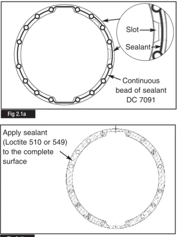
Clean mounting faces and threads thoroughly. Apply a continuous bead of sealant DC 7091 to the rear axle mounting face (Fig. 2.1a) Ensure the continuous bead of sealant is applied around the slots in the mounting face to achieve correct sealing, DO NOT apply the sealant over the slots (Fig 2.1a).
Apply sealant (Loctite 510 or 549) to the complete surface of the joint gasket (Fig 2.1b.)
NOTE:
The carrier to housing assembly must be completed within 15 minutes of applying the sealant to the mating surfaces. Reverse the removal operation sequence and torque fastening screws/nuts and drain plug to the specifications detailed inSection 6 Tightening Torques & Lubrication.
2
Maintenance
Introduction
In order to ensure reliable and efficient differential unit operation, maintenance intervals, use of lubricants and correct procedures specified by the manufacturer should be strictly observed (refer to Lubrication Maintenance Manual no. 1). For further information contact the manufacturer’s engineering department or refer to the ArvinMeritor Web site at www.arvinmeritor.com (technical library – manuals).
Spare parts
Use original Meritor spare parts only.
Differential removal and installation
1. If the vehicle is loaded, unload the rear axle before removing the differential.
2. Place the vehicle on level ground and chock the front wheels. 3. Rest the rear axle on two suitably strong axle stands. 4. Remove the drain plug from the rear axle bottom end and drain lubricant.
5. Engage differential lock before air pressure falls below 2.8 bars
6. Remove axle shaft mounting screws and washers. 7. Remove axle drive shafts.
8. Remove propeller shaft.
9. Disconnect compressed air lines and differential lock sensor switch coupling.
10. Remove differential carrier to rear axle housing fastening screws (leave two screws in place to prevent the differential from falling).
11. Safely support carrier assembly with suitable lifting tool to aid removal. Remove plastic protective plugs fitted to the
extraction screw holes. Fit extractor screws.
Remove final 2 carrier screws to withdraw carrier assembly. Mount the carrier assembly in a suitable fixture and remove the differential lock assembly as described in Section 5 Differential
Lock Removal. Fig 2.1b
Fig 2.1a Continuous bead of sealant DC 7091 Apply sealant (Loctite 510 or 549) to the complete surface Slot Sealant
Measure the internal distance between the service tool plates at three equally spaced points to determine the total width of the bearing
C
(Fig 2.3) (e.g. 44.63). Record dimensionC
it is required for Shim Pack calculation below.2
Maintenance
CAUTION
: Only original Meritor spare parts should be used.Use of non-original parts could seriously affect differential unit performance. Use of non-recommended lubricants will adversely affect performance and service life.
WARNING
: Waste oil disposal must be carried out in conformity with the legislation in force.CAUTION
: Differential carrier removal and handling should be performed using the specified lifting and carrying equipment.CAUTION:
During dismantling/reassemblyoperations always engage differential lock to ensure alignment of the splined sections and prevent shift fork bending and spline damage.
Finally ensure that:
• There are no leakages from air lines.
• Lubricating oil meets manufacturer’s specifications. • Differential lock cab warning lamp functions correctly.
Ring Gear & Pinion Adjustment
If a new ring gear and drive pinion are to be installed, the correct thickness of shim pack required between the inner bearing cup and the carrier must be determined.
When the correct shims pack has been identified the bearing preload on the drive pinion must be adjusted. The preload is controlled by the thickness of the spacer between the inner and outer cones of the pinion bearings.
Determining the Pinion Inner Bearing Dimension
Before assembling the carrier, measure the complete inner pinion bearing assembly compressed into the ArvinMeritor service tool CT 40 , as detailed below.
Place the complete bearing into service tool CT 40 and rotate it while tightening the tool (Fig 2.2). Tighten the tool until the bearing is completely seated (Fig 2.3).
Fig 2.2
Fig 2.3
Identifying the Carrier Class & Pinion Mounting Dimension
Note the carrier class stamped on the carrier housing
D
. This may be stamped on the carrier outer casing (Fig 2.4) or the carrier mounting face (Fig 2.4a). The table (Fig 2.5) contains the cross reference detail for carrier class codeD
to the mounting pinion dimensionE
(eg. 283.5mm)NOTE
: DimensionE
is essential to calculate the new shim pack requirements when the original ring gear and shim pack are not available.Shim Pack Calculation
Calculate the shims required using the appropriate procedure 1 or 2 below.
1. Calculating the Pinion Shim Pack Value - Original Ring Gear, Pinion & Shim Pack NOT AVAILABLE for Reference 1.1 The standard theoretical pinion mounting dimension
F
is235mm
1.2 Note the Pinion Cone (P.C.) value
G
marked on the drive ring gear (Fig. 2.6). This can be either a + value or - value, (e.g. + 0.1mm)1.3 Using the values identified for
C, E, F
&G
above calculate the shim pack requirements using the formula provided below.Formula:
E
-(
F
+/-G
)
-C
= Shim Pack Valuee.g. 283.50 - (235 + 0.1) - 47.63 = 0.77mm
NOTE
: Use a shim pack as close as possible to the calculation value obtained. Shims are available in thicknesses of 0.10, 0.15, 0.2 & 0.5mm. Fig 2.4a Fig 2.5 Fig 2.6 Carrier Class (D)Pinion Mounting Dimension (mm) (E) 0 283.60 1 283.58 2 283.56 3 283.54 4 283.52 5 283.50 6 283.48 7 283.46 8 283.44 9 283.42 10 283.40
2
Maintenance
Fig 2.4 10 +0,05 1 0/00 B/L 0,322. Calculating the Pinion Shim Pack Value - Original Ring Gear & Pinion and Shim Pack AVAILABLE for Reference. 2.1. Measure the thickness of the shim pack removed from
the old pinion/drive gear assembly. Use a micrometer or gauge and record the reading.
2.2. Read the Pinion Cone (P.C) value marked on the drive ring gear which is to be replaced (Fig. 2.6)
If it is a plus (+) number add it to the value recorded at point 2.1.
If it is a minus (-) number, subtract it from the value recorded at point 2.1.
Record the result of the above calculation.
WARNING:
The value obtained at point 2.2 above will be used to calculate the thickness of the shim pack required to be fitted between the INNER pinion bearing cup and the differential carrier to ensure a correct new final drive assembly. Spare shims which may be required between the INNER pinion bearing cup and differential carrier are available in thicknesses of 0.10, 0.15, 0.2 & 0.5mm2.3. Read the P.C. marked on the new drive gear (Fig 2.6). Either, add or subtract from the calculated value recorded at point 2.2 above.
NOTE:
Where the PC figure on the NEW drive gear is a + value it must be subtracted from the calculated value at point 2.2. Where the PC figure on the NEW drive gear is a - value it must be added to the calculated value at point 2.2Refer to the following examples which cover all the possible calculation combinations.
NOTE
: All values are mm.Example 1:
Original Shim Pack Thickness 0.75 P.C. marked on the OLD DRIVE GEAR -0.10
Resulting Value 0.65
P.C. marked on the NEW DRIVE GEAR +0.20 Thickness of new shim pack required 0.45
(0.65 - 0.20)
Example 2:
Original Shim Pack Thickness 0.65 P.C. marked on the OLD DRIVE GEAR +0.10
Resulting Value 0.75
P.C. marked on the NEW DRIVE GEAR +0.20 Thickness of new shim pack required 0.55
(0.75 - 0.20)
Example 3:
Original Shim Pack Thickness 0.70 P.C. marked on the OLD DRIVE GEAR +0.10
Resulting Value 0.80
P.C. marked on the NEW DRIVE GEAR -0.20 Thickness of new shim pack required 1.00
(0.80 + 0.20)
Example 4:
Original Shim Pack Thickness 0.85 P.C. marked on the OLD DRIVE GEAR -0.10
Resulting Value 0.75
P.C. marked on the NEW DRIVE GEAR -0.20 Thickness of new shim pack required 0.95
(0.75 + 0.20)
NOTE:
Use a shim pack as close as possible to the calculation value obtained. Shims are available in thicknesses of 0.10, 0.15, 0.2 & 0.5mm.NOTE
: All final drive sets are stamped with a number indicating the nominal backlash between pinion and drive gear obtained when machining was completed. This backlash value is shown on the drive gear outer diameter (Fig. 2.7)Fig 2.7
2
Maintenance
2
Maintenance
Carrier Assembly
If a new ring gear and drive pinion are to be installed, the correct thickness of shim pack required between the inner bearing cup and the carrier must be determined. Refer to Section 1 Ring Gear & Pinion Adjustment. When the necessary calculations have been completed and the correct shim pack has been identified continue with the carrier assembly detailed below.
CAUTION:
Do not attempt to assemble the carrier assembly before establishing the correct shim package requirements.1. Where applicable, Use a suitable press and correct size sleeve, to install the dust shield (deflector) on to the companion flange (Fig. 2.8).
IMPORTANT
: The spigot bearing has a larger radius on one side. this larger radius must be positioned facing the head of the pinion (Fig. 2.9). The bearing part number should face toward the operator.2. Using ArvinMeritor service tool CT 5, press the spigot bearing on the nose of the drive pinion until the bearing is flat against the gear head (Fig. 2.10). Ensure the tool locates correctly on the bearing applying force to the inner ring only (Fig 2.11)
Fig 2.9
Fig 2.10
Fig 2.11 Fig 2.8
A press force of 6 - 8 tons is required (Fig. 2.12).
3. Ball stake the pinion spigot in 10 places equally spaced (Fig. 2.13). The ArvinMeritor service tool CT 06 has only five staking balls present (Fig 2.14).
Mark the pinion to form a datum and the staking tool in two places at a 36 degree interval (Fig 2.15).
Align one of the marks on the staking tool with the datum mark on the pinion.
Apply a load of 20 ton and form 5 staking points (4 tons per staking point).
Remove the tool and align the second mark on the tool with the datum mark on the pinion. Again apply a load of 20 ton to produce the second set of five staking points.
CAUTION
: When under cutting of the pinion nose is present it may be necessary to adjust the position of the staking points to ensure they avoid any undercut, in this case a minimum of 5 staking points are required.2
Maintenance
Fig 2.12 Fig 2.13 Fig 2.15 Fig 2.1436 Degrees
4. Apply assembly oil to the pinion shaft (Fig 2.16) and press the inner cone firmly against the pinion head shoulder using ArvinMeritor service tool CT 44, which applies pressure only on the bearing inner cone face (Fig. 2.17). Apply a press load of 6 - 8 tons.
5. Press the outer cup of pinion bearing firmly into its bore in the carrier. Using ArvinMeritor service tool CT 43, which is the same size as outer race (Fig. 2.18).
Press the bearing until is squarely against the shoulder in the bottom of its bore (Fig. 2.19). Apply a press load of 6 - 8 tons.
2
Maintenance
Fig 2.16 Fig 2.17 Fig 2.18 Fig 2.19Assembly Oil
6. Fit the the correct value of shims previously calculated (Fig 2.20) into base of the inner bearing bore of the carrier (Fig 2.21).
7. Apply assembly oil to the bearing seat area of the carrier (Fig 2.22) and using ArvinMeritor service tool CT 42, press the bearing into the carrier until is squarely against the shoulder in the bottom of its bore (Fig. 2.23).
Apply a press load of 6 - 8 tons.
2
Maintenance
Fig 2.20
Fig 2.21
Fig 2.22
Calculating the Pre-Load Spacer
There are two methods of determining the correct pre-load spacer, with and without ArvinMeritor service tool CT 41. Follow the appropriate procedure below.
With Service Tool CT41
8. Fit the 2 service tool spacers CT 41 (Fig. 2.24) into position in the carrier (Fig. 2.25).
9. Using ArvinMeritor service tool CT 45, press the outer bearing cone on the pinion shaft firmly against the service tool spacers CT 41 (Fig. 2.26) using a press load of 6 - 8 ton.
CAUTION
: When using a press to fit the outer bearing cone on the pinion always support the pinion shaft with a suitable block of wood (Fig. 2.28). Failure to do this could result in damage to the carrier casting or drive gear assembly.2
Maintenance
Fig 2.24 Fig 2.25 Fig 2.26 Outer Bearing Cone Wooden Block Pinion Service Tool Spacer CT 41If a press is not available, use ArvinMeritor service tool flange CT 51 and ArvinMeritor service tool pinion nut CT 50, tighten the pinion nut to a torque value of 1350 - 1670Nm (Fig. 2.27).
NOTE
: Do not use a standard flange & pinion nut for this operation.The actions detailed above, either by press or using ArvinMeritor service tools CT 50 & CT 51, tightend by hand, will compress the service tool spacers CT 41.
10. Where applicable remove the service tool pinion nut CT 50 and service tool flange CT 51. Remove the the outer bearing cone and service tool spacers CT 41.
NOTE
: Ensure the pinion does dot drop onto the press bed when removing the bearing11. Measure the new compressed thickness of the two service tool spacers CT41, to determine the average size of each spacer. Add 0.25mm to the average value determined above and record this new value. Use the new value to determine the size of spacer to install between the helical driven gear and outer bearing.
Example:
Thickness of spacer (Tool CT 41) 12.826 Average Thickness = 12.826.
Add 0.25mm to determine spacer/s required =13.076
NOTE
: The spacers control the preload adjustment of the drive pinion bearings Always select a spacer as close as possible to the value calculated.Continue with reassembly from procedure 21.
2
Maintenance
Without Service Tool CT 41
12. Fit a master spacer
X
(maximum size 15.155mm) into position in the carrier (Fig. 2.28).13. Using ArvinMeritor service tool CT 45, press the outer bearing cone on the pinion shaft firmly against the master spacer (Fig. 2.29) using a press load of 6 - 8 tons.
Fig 2.27 Fig 2.28 Fig 2.29 Outer Bearing Cone Pinion Master Spacer
X
Wooden Block Pinion Head SupportCAUTION
: When using a press to fit the outer bearing cone on the pinion always support the pinion shaft with a suitable block of wood (Fig. 2.29). Failure to do this could result in damage to the carrier casting or drive gear assembly.14. Fit the input flange into position and tighten the pinion nut to a torque value of 1350 - 1670Nm
15. Set a DTI (Dial Test Indicator) against the head of the pinion shaft and set to
“0”
(Fig. 2.30).16. Move the pinion shaft and measure the axial movement recorded on the DTI. Record the measurement
Y
17. Using the dimension of the master spacer
X
and the DTI readingY
calculate the correct spacer value required following the calculation;X
-Y
- 0.08mm (coefficient factor) = Spacer dimensionExample:
Master Spacer
X
= 15.155mmPinion Shaft Axial Movement
Y
= 0.55mm Coefficient Factor = 0.08mm15.155 - 0.55 - 0.08 = Correct Spacer Value 14.525mm
NOTE
: The spacers control the preload adjustment of the drive pinion bearings Always select a spacer as close as possible to the value calculated.18. Remove the pinion nut and flange.
19. Remove the outer bearing cone and master spacer.
20. Position the calculated spacer identified above to provide the correct bearing pinion preload (Fig. 2.31). and continue
assembling the carrier
2
Maintenance
Fig 2.30
21. Using ArvinMeritor service tool CT 45, press the outer bearing cone of the pinion shaft again, firmly against the spacer/s (Fig. 2.32) using a press load of 6 - 8 ton. Rotate the pinion by hand to seat the bearings.
NOTE:
If a press is not available procede to point 22 and fit the flange.CAUTION
: When using a press to fit the outer bearing cone on the pinion always support the pinion shaft with a suitable block of wood (Fig. 2.32). Failure to do this could result in damage to the carrier casting or drive gear assembly.22. Fit the flange and tighten the pinion nut to a torque value of 1350 - 1670Nm.
NOTE
: The flange must be fully seated against the outer pinion bearing before the nut is tighten to the torque specification.The flange must be held with ArvinMeritor service tool CT 003 to tighten the nut and a torque multiplier will be required to achieve the correct torque value of 1350 - 1670 Nm. (Fig. 2.33)
23. Check the bearing preload, it should be 0.5-10Nm (Fig. 2.34). If the preload (torque) of the pinion bearing is not within 0.5 -10Nm, remove the pinion from carrier and follow the appropriate procedure below:
• To increase preload
install a thinner bearing spacer combination.
• To decrease preload
install a thicker bearing spacer combination.
2
Maintenance
Fig 2.32 Fig 2.34 Fig 2.33 Outer Bearing Cone Wooden Block Pinion Head SupportPinion Spacer
24. Apply assembly oil to the differential case (Fig 2.35). Install the bearing cones on both sides of the differential case (Figs. 2.36 -2.38).
Use a press and ArvinMeritor service tools CT 46 & CT 47. Press the cones squarely and firmly on differential cases with a press force of 6 - 8 tons.
NOTE
: The larger bearing is fitted to the drive gear side of the ring gear.2
Maintenance
Fig 2.35 Fig 2.37 Fig 2.36 Fig 2.3825. Turn the right hand side adjusting ring by hand and tighten into the disjoint cap (Fig. 2.39). Fit the RH differential bearing cup over the cone (Fig. 2.40). Fit the cap into position on the Differential (Fig. 2.41).
26. Safely lift the differential with ring gear, cup, R.H. cap and adjusting ring assembly (Fig. 2.42) using ArvinMeritor service tool CT 52.
2
Maintenance
Fig 2.39 Fig 2.40 Fig 2.41 Fig 2.4227. While tilting the assembly engage the spigot bearing (Fig. 2.43) and install the R.H. cap assembly into locating holes (Fig. 2.44).
28. Fit the cap screws and washers that hold the R.H- cap to the carrier (Fig. 2.45).
Tighten all the cap screws by hand four to six turns, then tighten to the correct torque value 200Nm+ 90°-105°.
29. Fit the L.H. split cap with a light plastic or rubber mallet (Fig. 2.46).
2
Maintenance
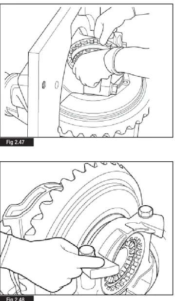
Fig 2.43 Fig 2.44 Fig 2.45 Fig 2.4630. Install the bearing cup and adjusting ring L.H. (Fig. 2. 47) and install the cap screws and washers that hold the L.H. Cap to the carrier.
Tighten all the cap screws by hand four to six turns (Fig. 2.48), then tighten to the correct torque value 200 Nm + 90°-105°.
31. Adjust the preload of differential bearings.
Using ArvinMeritor service tool CT 12, Tighten the crown wheel side bearing adjuster ring (Fig. 2.49) while turning the croqwn wheel by hand. When a resistance is felt at the crown wheel stop tightening the adjuster ring.
32. Back off the adjuster ring by 2 segments/notches.
33. Set a DTI gauge, diagonaly opposed, against each bearing cap (Fig. 2.50). Set both DTI gauges to
“0”
.34. Move to the opposite side of the crown wheel and tighten the bearing adjusting ring until there is movement on the DTI gauges.
NOTE
:
The bearing cap divergance figure is the combined reading of both DTI gauges. Example:Gauge 1 = 0.12mm Gauge 2 = 0.17mm
Bearing cap divergance is, 0.12mm + 0.17mm = 0.29mm. 35. Continue to tighten the bearing adjuster ring until a bearing cap divergance value between 0.15mm and 0.33mm is obtained. This will ensure the correct bearing pre-load is achieved.
2
Maintenance
Fig 2.49
Fig 2.50 Fig 2.47
2
Maintenance
37. Using ArvinMeritor service tool CT 12 slacken the adjusting ring on the drive gear side of the crownwheel and tighten the adjusting ring on the opposite side by the same amount, this will ensure the previously measured bearing cap divergance, and therefore, bearing preload is maintained (Fig. 2.53).
38. Check the gear for run out (Fig. 2.54). If run out exceeds 0.20 mm, remove the differential and check for the cause. 36. Check hypoid gear backlash (Fig. 2.51). For new gears the
new backlash should be initially set at 0.38 mm (Fig. 2.52). The back lash can be altered within the limit of 0.28 - 0.50mm to obtain a better contact position relative to the length of tooth.
NOTE
: Check the backlash in a minimum of 3 places.NOTE
: Adjust the backlash by moving the gear only.Fig 2.51
Fig 2.52
Fig 2.54 Fig 2.53
Tooth contact patterns of hypoid gear set.
With a brush, apply a thin coat of Prussian blue to the drive gear teeth (Fig 2.55). Rotate the pinion and examine the contact marks left by the pinion teeth on the drive gear teeth.
The information provided for Drive Side & Coast side below indicates correct tooth contact patterns. For detailed information regarding tooth contact pattern problems, causes and rectification advice refer to Section 3 Hypoid Gearing Contact
Drive side(Fig 2.56)
Central toward the toe over the face of the gear tooth and in the centre on the tooth profile.
Coast side(Fig 2.57)
Central toward the heel over the face of the gear tooth and in the centre along the tooth profile.
2
Maintenance
39. After the correct tooth contact patterns have been established, fit the adjusting ring locks and new screws (Figs. 2.58 & 2.59). Tighten the screws to the correct torque value 10-12 Nm. Fig 2.55 Fig 2.56 Fig 2.59 Fig 2.58 Fig 2.57
HEEL
TOE
HEEL
TOE
2
Maintenance
40. When the correct drivr gear tooth pattern and bearing preload are confirmed remove the pinion nut and flange.
41. Locate a new seal in position (Fig. 2.60). Using a mallet and seal driver CT 01 (Fig 2.61), carefully tap the seal into the carrier bore until the tool is flat against the top of the carrier.
42. Install the input flange onto the drive pinion shaft.
NOTE
: The flange must be fully seated against the outer pinion bearing before the nut is tighten to the torque specification. The flange must be held with ArvinMeritor service tool CT 003 to tighten the nut and a torque multiplier will be required to achieve the correct torque value of 1350 - 1670 Nm. (Fig. 2.62)Fig 2.60
Fig 2.61
43. Coat the shift fork slanting face with Molikote Gn Plus grease (Fig. 2.63). Install the shift fork into position in the carrier case with the protruding boss facing towards the outer bore in the differential lock housing (Fig. 2.64).
2
Maintenance
44. Compress the shift shaft spring (65 Kg force) using the ArvinMeritor service tool CT 48 (Figs. 2.65 & Fig 2.66).
Fig 2.63
Fig 2.64
Fig 2.65
45. While the spring is compressed insert it into the ArvinMeritor service tool CT 49 and remove from the spring compression tool CT 48 (Figs. 2.67 & Fig. 2.68).
46. Fit the shift shaft spring into the carrier case (Fig. 2.69) tapping the spring out of the assembly tool with a hammer (Fig. 2.70). Fig 2.67 Fig 2.68 Fig 2.69 Fig 2.70
2
Maintenance
2
Maintenance
47. With ArvinMeritor service tool CT 49, or a suitable screwdriver locate the spring correctly between the two shift shaft bores into the carrier casting (Fig. 2.71).
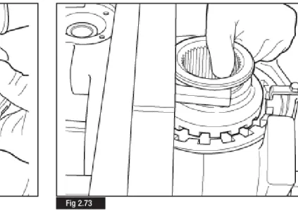
48. Whilst holding and tilting the shift fork, place the shift collar in position in the fork (Fig. 2.72). Ensure there is sufficient room between fork and cap (Fig. 2.73)
Fig 2.71
49. lubricate the cylinder bore with grease Molikote 44.
Apply grease Molikote 44 to the shift shaft (Fig. 2.74) and fit the shift shaft into the cylinder bore (Fig. 2.75).
Fit the 'O' ring, locating correctly in the piston groove. Generously lubricate the 'O' ring, piston (Fig. 2.76) with grease Molikote 44 and and carefully insert the piston into the cylinder bore (Fig. 2.77). Fig 2.74 Fig 2.76 Fig 2.75 Fig 2.77
2
Maintenance
2
Maintenance
50. Fit a new cover gasket (Fig. 2.78) and place the cover air intake in position (Fig. 2.79).
Fit the four capscrews and washers. Tighten the screws to a torque value of 10 -12 Nm.
Installation & Adjustment of the Differential
Lock Sensor Switch
NOTE:
The checking and adjustment of differential sensor switch should be carried out with the complete rear axle installed on the vehicle. However, the switch setting procedure can be carried out in a carrier rig using dummy halfshafts and test meter as shown in Fig 2.83.1. Before fitting the switch, coat the switch point with MoliKote GN Plus grease.
Apply sealant Loctite 573 to the threads (Fig. 2.80) and carefully screw the switch into the differential casing approx. 3 threads (Fig 2.81).
Fig 2.78
Fig 2.79
Fig 2.80
2. Check the differential lock engagement by applying air pressure air of 6 Kg/cm2 - 6 bar approximately (Fig. 2.82)
3.. As soon as the warning lamp in cab is illuminated (Fig. 2.83), screw the switch in a further one turn of the thread.
4. Tighten the lock nut on the switch to a torque value of 35 - 45 Nm.
5. Release the differential lock and ensure in this condition the warning lamp in the cab is off.
6. Repeat the above operations several times before running on the road
Fig 2.82
Fig 2.83
Hypoid Gear Contact Patterns
pg 40 Hypoid Gear Pattern Tables
3
3
Hypoid Gear Contact Patterns
OPTIMAL CONTACTS
DRIVE SIDE COAST SIDE
(CONVEX SIDE RING GEAR) (CONCAVE SIDE RING GEAR)
TOP TOP
HEEL TOE HEEL
BOTTOM BOTTOM
• DRIVE SIDE : Central favouring TOE in length and Central in the profile. • COAST SIDE : Central favouring HEEL in length and Central in the profile.
CONDITION “A”
DRIVE SIDE COAST SIDE
TOP TOP
HEEL TOE HEEL
BOTTOM BOTTOM
• DRIVE& COAST SIDE : Contact too close to the TOP • DRIVE SIDE : Contact too close to the TOE • COAST SIDE : Contact too close to the HEEL
• CORRECTIVE ACTIONS : Add Shims and Increase the Backlash to the maximum
CONDITION “B”
TOP TOP
HEEL TOE HEEL
BOTTOM BOTTOM
• DRIVE-COAST SIDE : Contact too close to the TOP
• CORRECTIVE ACTIONS : Check the Backlash, ADD Shims and re-set the Backlash
CONDITION “C”
TOP TOP
HEEL TOE HEEL
BOTTOM BOTTOM
• DRIVE-COAST SIDE : Contact too close to the BOTTOM
3
Hypoid Gear Contact Patterns
CONDITION “D”
DRIVE SIDE COAST SIDE
TOP TOP
HEEL TOE HEEL
BOTTOM BOTTOM
• DRIVE-COAST SIDE : Contact too close to the BOTTOM. • DRIVE SIDE : Contact too close to the HEEL. • COAST SIDE : Contact too close to the TOE.
• CORRECTIVE ACTIONS : Remove shims and reduce backlash to the minimum.
CONDITION “E”
DRIVE SIDE COAST SIDE
TOP TOP
HEEL TOE HEEL
BOTTOM BOTTOM
• DRIVE SIDE : Contact too close to the HEEL. • COAST SIDE : Contact too close to the TOE. • CORRECTIVE ACTIONS : Reduce the backlash.
CONDITION “F”
DRIVE SIDE COAST SIDE
TOP TOP
HEEL TOE HEEL
BOTTOM BOTTOM
• DRIVE SIDE : Contact too close to the TOE. • COAST SIDE : Contact too close to the HEEL. • CORRECTIVE ACTIONS : Increase the backlash.
Pinion Seal Replacement
pg 44 Disassembly pg. 45 Assembly
4
4
Pinion Seal Replacement
The pinion seal replacement detailed below may be carried out with differential unit installed on the vehicle.
Disassembly
1. Unscrew the nuts (1) securing the propeller shaft to the differential companion flange.
2. Disconnect the propeller shaft (2) and secure it to the chassis. (Fig. 4.1)
3. Block the rotation of the flange (1) using service tool CT03 (2). 4. Using a suitable wrench (3), torque multiplier (4) and service tool CT02 slacken the bevel pinion nut and withdraw the flange (1) (Fig. 4.2).
5. With a suitable tool raise the outer edge of the metal inner ring (1) in two opposite points. (Fig. 4.3)
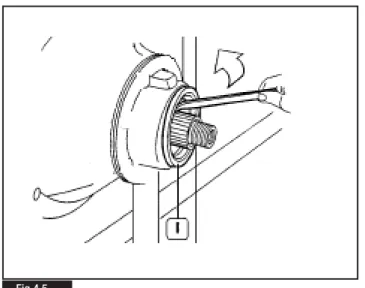
6. Pry with two levers (2) to withdraw the inner ring (1). (Fig. 4.4) 7. Pry with the lever in the direction shown by the arrow to remove the grommet (1). (Fig. 4.5)
Fig 4.1
Fig 4.2
4
Pinion Seal Replacement
Assembly
1. Thoroughly clean the seal ring seat and remove any trace of dirt or oil.
2. Position a new pinion seal ring (1). Fit service tool CT01 (2). 3. Using an ArvinMeritor service tool pinion nut CT 50 Tighten the pinion nut until the new pinion seal is located fully in the carrier (Fig. 4.6)
4. Remove the ArvinMeritor service tool pinion nut CT 50 and ArvinMeritor service tool CT 01 (2). Reassemble the flange and retain with a new pinion nut. Tighten the pinion nut to the torque figure specified in Section 6 Tightening Torquesusing a torque wrench and multiplier.
5. Reassemble the propeller shaft and tighten fastening nuts to the torque specified by the vehicle manufacturer.
Fig 4.6 Fig 4.5
Differential Lock Removal
pg 48 Differential Lock Replacement
5
5
Differential Lock Removal
The procedure detailed below provides a safe and efficient method for removing the differential lock components without causing damage to either the components or carrier.
1. Remove the carrier assembly from the vehicle as described in
Section 2 Maintenanceand mount securely in a suitable fixture.
2. Remove the four capscrews which secure the differential lock cover to the carrier.
3. Remove the differential lock cover and gasket.
NOTE
: Never reuse the existing gasket. Always fit a new gasket on reassembly.4. Using a copper or plastic faced hammer strike the outer face of the differential lock fork. This action should eject the differential lock piston sufficiently to allow removal from the housing.
5. Remove the differential lock piston.
6. While holding and manipulating the differential lock fork, remove the shift shaft from the cylinder bore.
7. Locate a suitable size diameter socket or sleeve, which is a minimum of 52mm in length, into the cylinder bore so that it abuts against the face of the differential lock fork.
8> Refit the differential lock cover and secure in place against the socket/sleeve with 4 M6 studs, washers and nuts, or M6 bolts (Fig 5.1). The studs or bolts must be a minimum of 50mm long. 9. Tighten the nuts/bolts evenly, ensuring the cover is kept square to the carrier face. This action will compress the differential lock fork and spring sufficiently to allow the differential lock fork to clear the lug of the cylinder on the carrier casting.
10. Carefully withdraw the differential lock fork and spring complete from the carrier by pulling upwards (Fig 5.2).
11. Remove the differential lock cover, studs or bolts and socket/sleeve from the carrier.
NOTE:
Check that the differential lock spring has not been damaged or distorted in any way during the removal procedure. If there is a doubt in the suitability of any component for further service, replace with a new ArvinmMeritor service parts.12. Reassemble the differential lock assembly as described in
Section 2 Maintenance.
Fig 5.1
Tightening Torque Values & Lubrication
pg 50 Tightening Torque Table pg 50 Oil Specification pg 50 Oil Change Intervals pg 50 Oil Capacity
6
6
Tightening Torque Values & Lubrication
Description Torque
Nm Degrees Kgm
1Drive pinion nut 1350-1670 135-167
2Lock nut sensor switch 35-45 3.5-4.5
3Cover capscrews 10-12 1.0-1.2
4 Bearing cap, capscrews (torque & angle procedure) 200 90o - 105o 20
(torque only) 630 - 846 63 - 84
Carrier to Housing screws (torque & angle procedure 100 105o - 115o
(torque only) 260 - 280 Drain Plug 80 +/- 20
1
2
4
4
3
Torque Values
Lubrication
Oil Specification
Oil Capacity
Hypoid Gear Oil MS 17X = 12.5 Litres
• A.P.I. GL - 5, S.A.E. 80W/140. MIL-2105-D or E • HD ECO 85W140 Mineral GL5
Oil Change Intervals
• Standard Applications 120,000 kms • Severe Applications 80,000 kms
Troubleshooting
pg 52 Troubleshooting Chart
7
6
Troubleshooting
Fault
1. Wheel hub noise and possible overheating
2. Anomalous knocks from the differential during acceleration / deceleration stages
3. Noise when travelling
4. Oil leakages
Possible causes
The oil used is not of the type specified by the manufacturer
Low oil level
Incorrect backlash between drive gear teeth Gears damaged
Bearings worn or maladjusted Incorrect use of retarder/exhaust brake
Driving wheel loose on hub
Differential unit splined sections worn
Low oil level in axle housing
Teeth and/or bearings worn or damaged Bearings maladjusted or damaged
Excessively high oil level in axle housing Breather blocked
Seal rings damaged Screws/nuts loose
Seal between axle housing and differential unit damaged
Remedy
Drain oil from housing and fill with new oil of the specified type
Top up oil level in housing
Remove bevel drive gear pair. Trace cause for possible gear damage. Adjust as required
Replace defective components Replace defective components
Check retarder/exhaust brake efficiency and setting. Look for possible damage to bevel drive gear pair and bearings
Check wheel nuts at regular intervals and tighten, as required Replace worn components
Top up oil level
Replace damaged components
Adjust bearings and replace, as required
Check oil level Clear/replace breather Replace damaged seal rings
Clean threads, coat with sealant if necessary, and tighten to the specified torque
Remove differential unit, check and clean all sealing surfaces and coat parts concerned with sealant, as required
For further information contact ArvinMeritor HVS Limited Commercial Vehicle Systems Grange Road, Cwmbran South Wales NP44 3XU - UK Tel: +44 (0) 1633 834238 Fax: +44 (0) 1633 834191 www.arvinmeritor.com/tech library Copyright 2007
ArvinMeritor Automotive All rights Reserved
Publication MM-0700EN
Descriptions and specifications were in effect at the time of this publication and are subject to change without notice or liability. Meritor reserve the right to make design improvements, change or discontinue parts at any time