Preventive Grinding Moves into the 21
st
Century on
Canadian Pacific Railway
Robert deVries Canadian Pacific Railway
Suite 700 Gulf Canada Square
401 - 9th Avenue
Calgary, Alberta, Canada T2P 4Z4 Telephone: 403 319 7758
Fax: 403 205 9050 E-mail: rob_devries@cpr.ca
Peter Sroba
Centre for Surface Transportation Technology National Research Council Canada
160 Arbour Lake Way N.W. Calgary, Alberta, Canada T3G 3W9
Telephone: 403 208 7063 Fax: 403 241 7272 E-mail: peter.sroba@nrc.ca
Eric Magel
Centre for Surface Transportation Technology National Research Council Canada
179 Citadel Meadow Close N.W. Calgary, Alberta, Canada T3G 4T4
Telephone: 403.239.6022 Fax: 403.239.6210 E-mail: eric.magel@nrc.ca
ABSTRACT
For over 30 years, the Canadian Pacific Railway (CPR) has been grinding their rail to reduce operating costs on their high curvature, heavy grade alignment. CPR found that rail grinding best practice was a preventive rail grinding strategy and implemented this practice over 10 years ago. CPR has progressively applied new technology into the track and contracted the latest rail grinding equipment to reduce the costs of rail maintenance, reduce wheel and rail wear, and in the process, reduce fuel cost. In the last 2 years CPR has undertaken to further refine their preventive grinding strategy by commissioning the National Research Council of Canada (NRC) to undertake a rail grinding study in the high tonnage Coal Route in Western Canada. Rail grinding cycles have been extended on sharp curves from 18 to 25 MGT, optimal rail profiles have been radically changed which required new grinding patterns and grinding speeds. The grinding program on CPR has been substantially improved by these optimal profiles, grinding cost per finished mile maintained have been reduced, rail wear has been reduced and the rail grinders now cover more territory than ever before.
Index terms: rail grinding, rail profile, wheel wear, rail wear, wheel/rail wear control
1.0 Introduction
In the early 1980’s Canadian Pacific Railway (CPR) was using profile grinding as a means of controlling rail problems such as low rail corrugations and plastic flow, high rail gage face wear and shelling. As early as 1982 CPR started testing various grinding strategies on the high tonnage coal route between Golden and Roberts Bank in British Columbia. This track is one of the toughest in the world to maintain. The track structure consists of curvatures varying between two and eleven degrees for approximately 50% of the 500 route miles from Golden to the port. Temperature extremes in the Thompson River Valley range from +43C (110F) to –34C (-30F).
In the early days the annual tonnage was 60 MGT with nominal axle loads of 33 tons. The rail was 132 lb / yd with 1.3% chromium steel in curves greater than three degrees with a hardness of 325BHN minimum, with conventional 260BHN standard carbon rail in mild curves and tangent track. Ties were typically an eight foot Douglas Fir softwood fastened with cut spikes with sixteen inch eccentric plates.
In 1986 new rail grinding patterns were developed by CIGGT and implemented in Western Canada using a 120 stone rail grinder travelling at 2.5 mph. The grinding technology in these days used 20 hp grinding motors, with eight computer controlled grinding patterns with maximum angle ranges of 26 degrees gage and field. CPR demonstrated that one grinding pass on sharp curves at cycles of 17 to 20 MGT was more economical than grinding 2 passes at 25 to 30 MGT [1].
In 1987 CPR adopted deep head hardened heat-treated alloy rail from Japan to further reduce rail fatigue. The surface hardness of this rail was 370-390 Brinell. CPR also adopted an intermediate grade rail for tangent and mild curves with a 325-340BHN hardness.
In 1990 CPR implemented grinding patterns with an angle range of +/- 32 degrees. Further testing by NRC, from 1989 to 1991, demonstrated [2, 7] the benefits of implementing a new, more frequent, preventive rail grinding strategy using new optimized profiles. These profiles were designed to prevent the formation of corrugations on the low rail and high rail gage face shelling. NRC initially developed four templates for the NRC/Loram BAR Gage – high rail sharp, high rail mild, low rail mild and sharp, and tangent track. This design was revised in 1991 to include a comprehensive set of eight templates to be maintained on curves with one grinding pass at grinding cycles of 8 MGT on sharp curves, 25 MGT on mild curves (less than 3 degrees) and 45 MGT on tangent track. The grinding cycle was dependent on the track curvature, the hardness of the steel and the track gage. An 88 stone production grinder started grinding to these templates in Western Canada in 1993. This rail grinder had 20 hp grinding motors and rail grinding patterns with a deeper angle range of between 45 degrees to gage and 26 degrees to field. One pass was used at 3.6 mph to complete the work.
In 1996 CPR started to purchase a new 8 inch crown radius rail profile (compared to the standard 14 inch crown of the AREA 136 lb/yd profile) with a modified rail gage corner to reduce wheel rail contact
stresses. This profile minimized the amount of grinding required to produce the optimal NRC profile. Since that time, significant production improvements have been realized through the introduction of new grinding machine technology and improved rail grinding management (refer to § 7.0). Since 1999, high production rail grinders have 30 hp grinding motors and over 100 computer controlled grinding patterns stored in the on-board computer. CPR also has a full time Rail Grinding Supervisor and three Rail Grinding Specialists who manage the programming and in-field inspection of the Rail Grinding and Ultrasonic Testing programs [5].
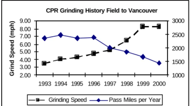
Figure 1 shows the history of grinding on the 80 MGT track between Field and Vancouver, since 1993. The figure shows that CPR has been continuously improving the grinding speed and reducing the total pass miles ground. This is due to harder rail steels, elastic fastenings, improved grinding machines, and better rail grinding management strategies.
Figure 1: CPR Rail grinding history, Field to Vancouver, Western Canada. Total pass piles and average grind speed (mph), 1993 to 2000.
CPR had been preventive grinding for over 10 years and the benefits are well documented [1, 2, 3, 4, 5, 6, 7, 8, 10, 18]. CPR suspected that they could reduce the amount of grinding on the newer premium steels in curves [9] as these rails were more resistant to higher contact stress and therefore less likely to flow, crack and/or change profile between grinding cycles. CPR wanted to reduce the rail wear by reducing the grinding effort. This would also reduce the grinding budget and have one grinding machine cover more territory. This propelled CPR into the 21st century of preventive rail grinding.
CPR commissioned NRC in July 1999 to measure and manage the risk of reducing the number of grinding cycles from four to three on the Coal Route. This would increase the grinding cycle tonnage from 18 to 25 MGT. CPR had dealt with three cycles in the past when a high fire risk prevented grinding in the heavily forested areas of British Columbia. The tonnage over the main line from Golden to Vancouver was 80 MGT per year. Coal trains were hauled by three 4400HP AC traction locomotives in the steeper grades and axle loads had increased to 35 tons. Frame braced trucks were the standard for the coal fleet. Cut spikes were replaced in curves of six degrees and greater with a rolled plate held down by five screw spikes with spring washers and Pandrol e-clips [4].
2.0 Key Features of the 1999 CPR
Preventive Grinding Strategy
CPR has been using a preventive grinding strategy in Western Canada since 1993. The pass mile to finished mile ratio was 1.004 in the year 2000. Some of the key features of the grinding strategy in 1999 [5] were:
1. The preventive one pass grinding cycle was rigorously maintained for the entire system using 1.5 high production rail grinders with two 96 grinding stones powered by 30 hp grinding motors. The average grinding speeds were six mph in sharp curves and twelve mph in mild curves and tangent track.
2. Typically four grinding cycles were performed on sharp curves, two on mild curves and one on tangent track each year on the high tonnage coal corridor. The strategy was to grind at a shorter cycle time in the winter (when shells and spalling is most likely to occur) and skim grind at longer cycles in summer.
3. The specified grinding templates were the eight NRC/Loram BAR Gage design (see table 2 and figure 5).
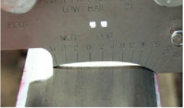
4. In 1994 CPR experienced low rail centre ball spalling problems [19]. Also the NRC/Loram BAR Gage L2 and L3 templates could not be achieved with one pass of the rail grinder at 18 MGT grinding cycles. From 1995 CPR has maintained the low rail to a 10 inch radius over a wide contact band (see figures 2 & 3).
2.00 3.00 4.00 5.00 6.00 7.00 8.00 9.00 1993 1994 1995 1996 1997 1998 1999 2000 Grind Speed (mph) 1000 1500 2000 2500 3000 CPR Grinding History Field to Vancouver
5. Grinding of high rails was excessive as the grinding metal removal was influenced by the grinding speed and horsepower delivered to the low rail (see figures 2 and 4). The grinding machine did not have the capability to reduce power from rail to rail.
6. There were 2 templates used for tangent track grinding: the NRC – TG and TF (refer to § 4.3.1).
7. Rail steels in sharp curves were premium Japanese deep head hardened rail on elastic fastenings.
8. Track Geometry car records demonstrated that there were few sharp curves with wide gage greater than 0.5 inch.
9. NRC analysis of hollow worn wheels on the CPR coal fleet and other traffic fleets demonstrated that less than 7% were more than 2mm hollow [11, 12]. It is suspected that the reason for this is the wheel shelling problems on CPR as well as item four and six mentioned above.
Figure 2: NRC BAR Gage template L2 on low rail of sharp curve showing large grinding requirement on gage and field at 18 MGT to produce the profile.
3.0 The Coal Route Test Program
To manage the risk of potential rail failure, NRC established two monitoring and one test site on the Coal Route in July 1999 to record the base case rail conditions and wear rates prior to starting the longer grinding cycles.
3.1 Monitoring Sites
The rail monitoring sites were established in the Mountain and Thompson Subdivisions with steep
grades, sharp curves and high tonnage. These sites were used to monitor rail condition before each grinding cycle (of 25 MGT) for: rail profile referenced to the NRC/Loram BAR Gage, the
progress of surface defects, and lubrication standards.
Figure 3: Low rail at 18 MGT cycle with a Star Gage showing the rail has a 10 inch radius.
Figure 4: NRC BAR Gage template H4 on high rail of sharp curve showing less grinding is required than on the low rail to produce the NRC/Loram BAR Gage profile.
3.2 Shuswap Test Site
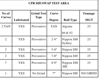
One test site was established on the Shuswap Subdivision, located 75 miles east Kamloops, BC. The test area was three miles long with predominately sharp curves. Train speeds averaged 25 mph, at under balanced speed, on timber tie track. The rail in the curves consists of predominantly 136 lb/yd, Japanese, deep head hardened premium rail. The annual tonnage on the test site was 80 MGT. Curves sharper than 5.5 degrees had pandrol plates. The main objective of the intensive rail-monitoring site was to manage the risks of implementing the longer preventive grinding cycles in the Western Canada territory. If any serious failure of the strategy was to take place, CPR and NRC would see it happen here. CPR also specified the requirement for an economic analysis to prove the benefit of the longer preventive grinding cycles. There was one seven degree curve, in new rail condition, in the test area left unground to verify the need for grinding rail. The test curve distribution is shown in Table 1. The following measurements were performed at each 25 MGT interval:
• rail profile using the MiniProf measurement gage • dye penetrant to enhance surface cracks • track gage measurement
• lubrication friction values
Table 1: CPR Shuswap test area – Test rail layout
CPR SHUSWAP TEST AREA
No.of Curves Lubricated Grind Test Type Curve
Degree Rail Type
Tonnage MGT
2 TAN YES Preventive TAN Algoma 86 & 92
25 2 YES Preventive 2-4º Nippon DH
Sydney
25 2 YES Preventive 5-6º Nippon DH 25 2 YES Preventive 7-8º Nippon DH 25 7 YES Preventive 8-9º Nippon DH
/HE
25 1 YES No Grind 7º' Nippon DH NO GRIND
4.0 Optimizing Rail Profiles
CPR as well as most North American railways standardized on the eight NRC 8” railhead profiles (figure 5) designed in 1991 [7]. Those NRC designs compensated for the rail wear rates and plastic flow on steels used in those days. On tangent rail, for example, the crown radius quickly flattened from eight inches to twelve inches over a typical grinding interval. An average of ten inches would remain on curve low rail for most of the NRC recommended grinding cycle. The TT profile was designed for tangent track, The H1 - H4 profile progressively larger gage corner relief, in steps of about 0.5 mm, while the L1 – L3 profile progressively larger field side relief. The graduated relief allows this family of profiles to be applied to a variety of track conditions, including wide gage, large dynamic rail rotations and soft metallurgy.
The NRC/Loram BAR Gage templates were developed with application guidelines to maintain a two point conformal contact with respect to the “average worn” wheel. Considerable emphasis was placed on developing this ‘proper’ average. The primary objective was to prevent gage corner collapse under excessive one point contact loads. Proper gage face and top of rail friction management was recommended to minimize the impact on wheelset steering performance.
Figure 5: Shows the NRC/Loram BAR Gage templates as used by CPR from 1993 to 1999.
4.1
Rail Stresses and Pummeling
Contact fatigue of the rail surface is due to excessive contact stress and creepage. Both contact stress and creepage are governed by the wheel/rail contact geometry, which in turn depends not only on the
a) b) TT TT L1 L2 L3 H1 H2 H4 H3
initial, unworn geometry of each component, but also the changes in geometry that occur with wear, fatigue and plastic flow. As an exa mple: wheel/rail creepage tends to pull metal from the high-rail shoulder into the gage-corner, filling in any initial relief. The high rail then takes the shape of the average wheel. The 50% of wheel population that has more flange-root metal than average will steer well through the curve but apply a very high normal stress to the gage corner, contributing to subsurface fatigue.
These are the 1-point conformal and non-conformal contacts. The other half of the wheel population - the 2 point contacts – run with compromised steering performance and continue to plastically deform and wear the surface (at a rate that depends primarily upon the friction conditions).
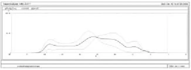
Figure 6: Shows the distribution of accumulated contact fatigue damage for several low rail profiles.
Modeling software has proven valuable for the design of optimal rail profiles that in practice must deal with a distribution of wheel profiles – from unworn to very worn, new to hollow, wide flange and thin
flange. NRC has developed a Profile Optimization (Pummeling) Model that applies measured worn wheel profiles to a truck characteristic of that fleet and derives distributions of contact stress, fatigue damage, stability and curving performance on rail profiles for specific track curvatures. Through an iterative process, the model is used to engineer rail profiles that optimize the wheel/rail interaction in tangent and curved track.
The accumulated normal contact stress between wheel and rail for the population of wheel profiles analyzed may be plotted in a Pummeling Diagram. Figure 6 shows the distribution of accumulated contact fatigue damage for several low rail profiles. The end result was the design of a significantly different low rail profile for all CPR curves that minimized fatigue damage between grinding cycles.
4.2
Rail Template Designs for CPR
Table 2: Comparison of the old NRC/Loram BAR Gage templates from 1993 with the new CPR design from 2001.
High Rail
Template
Old New Low Rail
Template Old New Sharp Corrective H4 H Correct L3 L10 Preventive > 8o H4 H > 8o L3 L10 Preventive 5o - 8o H3 H 5o - < 8o L2 L10 Preventive 2.5o - < 5o H2 H 2.5 o - < 5o L2 L10 Preventive 1.5o - < 2.5o H1 H 2.5o L1 L10 Preventive < 1.5o H1 TF2/ TT < 1.5o L1 L10 Tangent Slow Speed TG2/ TF2 TG TG2/ TF2 Tangent High Speed TF TF2 Tangent Crushed Hd TF TF2
For the CPR Coal Route, 1000 wheels from the coal fleet, 200 intermodal, 164 grain, 48 tank car and 38 box car wheels were analyzed to verify their impact
on rail profiles. A pummeling analysis was carried out to determine the accumulated normal contact stresses imposed by these 1500 wheelsets on rail profiles measured just before the 25 MGT grinding cycle. These curves were in the Shuswap test area and the specific curvatures analyzed were three, six and eight degrees [15]. The wheelset angles of attack and rail coefficient of friction were included in the analysis. The analysis showed that the current NRC/Loram Bar Gauge profiles were not optimal for the Coal Route. The 8-template NRC family was replaced with a new family of four custom rail profiles designed specifically for the CPR System. A comparison is shown in Table 2. The benefits of these profiles are: increased rail life in curves and tangent track, reduced grinding effort, lower lateral track forces (through better steering overall), increased wheel life and reduced fuel consumption.
4.2.1
Tangent Track Profiles
Most North American railways conscientiously apply a central 200 mm radius running band to all tangent rail. This means that as track geometry, bogies, ties and fasteners improve, more and more wheels are running continuously at the same contact band on the wheel tread, a practice that promotes wheel hollowing. In 1997 NRC developed two tangent templates for CPR that provide two distinct running bands, one biased to field and other biased to gage – in order to spread wear across the wheel treads and inhibit hollowing and the development of a false flange. These two profiles, CPTF and CPTG were modified based on the additional wheel profile data available in this study, field experience with grinding the initial profiles and also to specifically address a CPR problem of crushed heads in some tangent track sections.
CPR has an increasing incidence of crushed heads occurring in the older rail in tangent track. This rail was analyzed by NRC and found to be dirty steel with several locations of large and small inclusions. Surface fatigue cracks initiate at the mid-gage location on the railhead and gradually spread across the head to the field side. For crushes that have not reached an advanced stage or for rail prone to form crushes, reducing the high stress concentrations on the gage side of the rail can prevent future growth. The CPTF was developed to shift the contact distribution to the field side assuming that there was healthy metal underneath the wheels. The CPTF-2 is an improvement in the design as it not only achieves
the shift but also reduces the overall stress levels. Figure 7 shows the contact stress distribution on the rail head. The CPTF-2 also reduces the likelihood of hunting in high speed tangent track.
The previous CPTG profile required considerable field relief by grinding to accomplish the gauge bias on the rail head. The modified CPTG-2 requires less field relief (by 0.5 mm) and achieves the desired gage bias (see figure 7). The darker line in the figure shows the contact distribution across the wheel tread from running equal distances over the two tangent profiles. The two profiles will spread wear across the tread and reduce both the rates of wear and fatigue. CPR alternates the grinding of these two profiles in successive subdivisions. Where train speeds exceed 45 mph and the rail is prone to crushing, the CPTF-2 is used. The CPTF-2 and the existing NRC TT template can also be used for very mild curves.
Figure 7: The distribution of contact across the rail head in tangent track when the CPTG -2 and CPTF-2 rail profiles are applied. The darker line is the average of the 2 contact bands.
4.2.2
High Rail Profiles
Optimal high rail profiles must avoid concentrations of stress and fatigue but also maximize the vehicle curving performance. Pummeling analysis showed that the NRC / Loram BAR Gage high rail templates (H1 to H4) encounter excessive contact stress when mated with the measured CPR worn wheels. A stress concentration found at 35 degrees corresponds well to field observations of fatigue that initiates at this location (see § 11). The measured CPR worn rail profiles were run through the analysis and an improved high rail profile (CP-H) was developed for mild and sharp curves. This profile considerably reduces the metal removal required to maintain the shape compared to the previous NRC/Loram BAR Gauge profiles. Although the difference from the H2 is a modest 0.12 mm on sharp curves, about 1.0 mm less metal needs to be ground each cycle to re -profile the rail compared with the H4. The improved
wheelset steering and much better contact stress distribution will minimize wheel/rail wear and contact fatigue and reduce locomotive fuel consumption. Measurements in the field have verified that with lubrication the premium steel in the high rail of sharp curves will maintain the CP-H profile with a only a small amount of plastic flow between grinding cycles of 25 MGT.
4.2.3 Low Rail Profiles
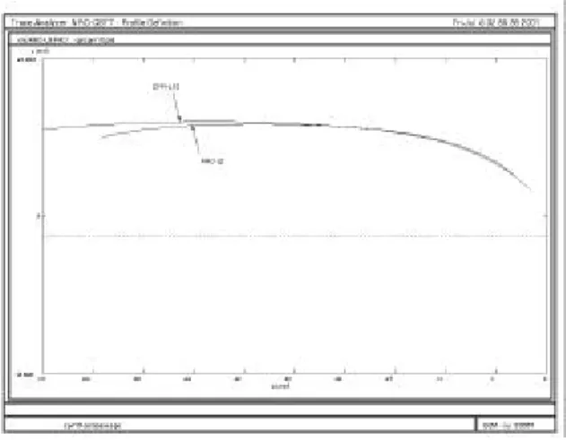
In the past CPR was grinding the low rail of sharp curves with heavy field side relief to minimize damage caused by hollow worn wheels. Wide gage further exacerbated the problem. CPR’s most recent experience [19] demonstrated that the low rail of premium steels could be maintained to a flatter radius and therefore less metal needs to be removed.
Figure 8: Shows the comparison of the new CPR-L10 (top line) and previous NRC -L2 rail template. There is a significant reduction in metal removal required to produce the profile each grinding cycle.
A pummeling analysis was carried out on the three (NRC/Loram BAR Gage) low rail templates, and it was found that for the current condition of CPR hollow wheel and wide gage there was little impact of the low rail profile on steering moments of trucks. The current practice was achieving a wide central contact band of ten inch radius. Also NRC verified from the Shuswap test site that this profile on premium steel flattened to a fourteen inch radius by 25 MGT and the rail remained relatively free of surface fatigue. A ten inch radius could be managed with one pass of a high production rail grinder. NRC developed a new CP-L10 which reduced the wheel /
rail contact stress. Field trials verified that the profile was suitable for both mild and sharp curves. The CP-L10 reduces metal removal by 1.8 mm compared to the NRC-L2 as shown in figure 8, which translates into improved rail grinding production and increased rail life.
5.0 The Optimal Metal Removal Rate
The optimal wear rate is the rate of wear required to just control rail surface fatigue. Insufficient wear results in rail fatigue, while excessive wear reduces rail life. The optimal wear rate will vary across a property and depend on differences in tonnage and axle load, type of traffic, rail metallurgy, track curvature, environment / season, track gage, lubrication standards, etc. Under preventive grinding, the grinder only removes a thin skin of fatigued and micro-cracked metal from the rail surface, artificially controlling the wear rate but leaving behind a healthy work-hardened layer. NRC determined the optimal wear rate by first analyzing service worn premium rail samples removed from relay rail in the Shuswap, just before the 25MGT grinding cycle. These samples were analyzed to determine the fatigue crack growth rates and direction of propagation [14]. As shown in Figure 9, a micrograph of RCF cracks from a sharp curve (8º20”) high rail, all of the cracks are located at the gage corner and gage shoulder. There is substantial plastic flow at the gage corner of the rail penetrating to a depth of about 2mm. This plastic flow is reduced in depth and extent at the gage shoulder with very little or no plastic flow at the crown. The micrograph shows long (1.5mm), intermediate (0.7mm) and short (0.18mm) cracks. The short cracks were most likely initiated after the rail was last ground while the intermediate and long cracks were initiated and not removed by the previous grinding cycles. Both the plastic flow and the crack pattern are indicative that almost all leading wheelsets pummel the rail at the gage corner and gage shoulder. This rail needs further gage corner relief to distribute the RCF damage along the entire width of the rail. The new high rail template and a proper lubrication strategy will also reduce gage corner contact stresses. The 0.18 mm (.007 inch) depth of initiating cracks is manageable with rail grinding at 25 MGT grinding cycles.
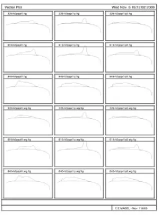
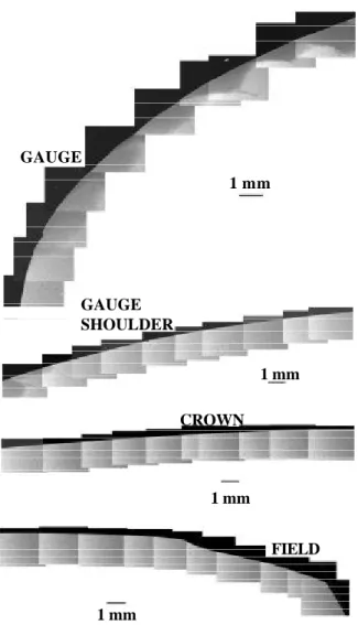
NRC next examined the grinding “metal removal plots” generated from before and after grind profile measurements at the test curve sites (figure 10). These were compared to dye penetrant photographs (figure 11) showing the state of cracks on the rail surface to determine if the metal removal at various locations on the rail was sufficient. They were examined over several grinding cycles on each curve to determine the optimal grinding pattern design and the minimum metal removal required to control crack formation and growth.
Figure 9: A Micrograph of a rail sample from CPR Shuswap Sub showing RCF cracking of premium (Nippon 1995 DH) high rail laid in an 8020’ curve. The rail carried 25 MGT since the last one pass grind.
(A) (B)
Figure 10: CPR-H template overlaid onto a 5.5 degree curve after 25 MGT traffic. (A) before grinding, (B) after grinding.
The optimal metal removal graph (figure 10) demonstrates that the high rail with premium steel in a sharp curve is close to the CPR-H profile. The after grind profile shows that the pattern used and the speed used for grinding over relieved the rail gage shoulder and field corner.
Figure 11: Shows the state of crack highlighted with dye penetrant on surface of this 5.5 degree curve high rail just before the 25 MGT grinding cycle.
GAUGE 1 mm GAUGE SHOULDER 1 mm FIELD 1 mm CROWN 1 mm
By grinding to the new CPR-H template the wheel contacts will be spread over a wider wear band and reduce the contact stress causing the deeper cracks at the gage corner and gage shoulder.
The next step was to determine the metal removal for each of CPR’s grinding patterns at various grinding speeds.
6.0 Grinding Pattern Refinement
CPR has generally used the same grinding patterns since 1993. These patterns were designed to match the existing rail condition to the NRC/Loram BAR Gage profiles. As grinding machine technology and configurations changed over the years the patterns were automatically mapped to the new equipment, introducing minor variations from the original pattern. This combined with changes in rail profiles resulted in patterns not well suited to producing the new CPR template designs.
A redesign of the grinding patterns was necessary to improve efficiency and produce a close conformance to the NRC profile in one grinding pass. CPR tightened pattern angle ranges used on the field side to 8 and 12 degrees on both the low rail and the high rail to replicate the needs of the new NRC templates. This freed up some grinding power on the 96 stone rail grinder to be used in other areas of the railhead and therefore increase grinding speed or metal removal. Also CPR is designing a complete set of patterns that mirrored the existing patterns but with reduced horsepower. This will allow a flat low rail to be ground at 100% power and the high rail to be ground at 70% power as less metal needs to be removed from the high rail each cycle, which will result in increased high rail life.
The success of a grinding plan is dependent on accurate metal removal studies and knowledge of how patterns work to produce the final rail profile. On CPR, metal removal testing is a continual process involving both CPR and the contractor [5]. These studies are made into charts, memorized and understood by the specialists to properly prepare the grinding plan. The specialists fine tune their understanding by performing post grinding inspections.
7.0 MANAGING THE PREVENTIVE
GRINDING PROGRAM
One 96 grinding stone machine, full time, and one 96 grinding stone machine for one to two months per year maintain the track from Vancouver in the west to New York in the east.
The benefits of the 25MGT preventive grinding cycle would not have been possible without vigilant management of the grinding program. Cycle intervals, grinding pattern selection, and rail condition are closely monitored throughout the program and adjusted to meet changing conditions. CPR has full time: a Rail Grinding Supervisor and 3 Rail Grinding Specialists. They perform many tasks, including: pre and post inspection of the rail to monitor the grinding process, selecting the proper NRC rail profiles, selecting the best one pass grinding patterns and speed, ensuring the grinder is supplied with water and fuel, and working with the dispatcher to get good work blocks [5].
The goal of every grinding plan is to have finished rail profile be within .018 mm (.007 inches) of desired shape. One of the key components of CPR’s rail grinding program is the pre-inspection process. Every curve is hand measured using the NRC/Loram BAR gage and the templates shown in Table 2. The pre-inspection is completed shortly before the planned grind. The Grinding Specialist accompanies the local roadmaster or his assistant and both perform a track patrol of the entire area to be ground. The close interaction between the grinding team and the local staff provides the opportunity for both parties to understand and agree to all the decisions that must be made before the execution of a grinding plan. The local roadmaster supervises the day to day operation of the rail grinder to complete the work in their subdivision. Closely working with the dispatcher will also secure the maximum number of work blocks. Following these steps ensures: the grinding program is strictly adhered to, proper supervision of the grinding operation, high production during the work blocks, coordination of the back up hi-rail water trucks to manage the risk of fires, and a safe operation.
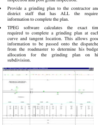
CPR uses a software program called TPEG (figure 12) to ensure the success of the high speed production rail grinding program. This program allows the user to do many things:
• Maintain a permanent record of past rail grinding plans. The permanent record is important for pre-inspection and post grind pre-inspection.
• Provide a grinding plan to the contractor and district staff that has ALL the required information to complete the plan.
• TPEG software calculates the exact time required to complete a grinding plan at each curve and tangent location. This allows good information to be passed onto the dispatcher from the roadmaster to determine his budget allocation for the grinding plan on his subdivision.
Figure 12: Shows a sample of the CPR -TPEG rail grinding program output.
Even though track maintenance time is reducing, figure 13 demonstrates how CPR has maintained a preventive grinding strategy with passes per finished track mile very close to one since 1993. The grinding team and the planning process ensures that this target is well managed and maintained.
Figure 13: Passes per track mile and Spark Ratio for CPR grinding in Western Canada, 1993 to 2000.
8.0 Preventive Grinding after 150 MGT
of Testing
At the conclusion of July 2001 the grinder had completed five preventive cycles of 25 MGT. NRC had developed modified rail profiles (see § 4) that were implemented in January 2001. CPR has developed modified grinding patterns to grind to the modified profiles for the July 2001 grinding cycle. The metal removal rates by the grinder are therefore not fully fine tuned for the new designs.
The benefits to CPR of longer grinding cycles on the System territory are listed as follows:
• Rail surface condition (visible surface defects) was much better than when the 18 MGT cycles were in place.
• Sharp curve annual rail wear from grinding and traffic has been significantly reduced on high rails and slightly increased on low rails. New grinding patterns that reduce the metal removal on the high rail (while maintaining maximum metal removal on the low rail) will reduce the high rail metal removal even further.
• More track miles and pass miles can be completed each year with the same machine, or the grinding budget can be reduced. An extended grinding cycle of 25 MGT resulted in annual saving is $440,000 US in the year 2000 grinding budget. In Western Canada there has been a reduction of 224 pass miles from the 1999 program.
• Cost per pass mile is presently 57% of the 1992 cost per pass mile.
8.1 Test Site Results
At the end of the test period, the economic benefits to CPR were evaluated. The following information was compared: total wear from grinding and traffic on the high-rail gage-face, the top of the high and low-rails, the severity of surface defects and the total grinding budget for the year.
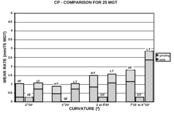
The wear data is shown in Figure 14 and 15 and the results are summarized in as follows:
0 1
1993 1994 1995 1996 1997 1998 1999 2000
Passes per Mile
0% 10% 20% 30% 40% 50% 60% CPR Grinding History
Figure 14: Grinding in the Shuswap test site showing total wear from grinding and traffic at 18 MGT cycles. Also shown is the no grind wear.
Figure 15: Grinding in the Shuswap test site, showing total wear from grinding and traffic after 150 MGT at 25 MGT cycles.
• The seven degree no grind curve exhibited the highest gage face wear, 16.3 times greater than other typical sharp curves. Although the vertical wear on the top of the high and low rail were lower than other sharp curves, the rail developed sever spalling on both rails. This is not a practical option for CPR.
• For curves between seven and 8.5 degrees in curvature, the 25 MGT cycle, when compared to the 18 MGT cycle, demonstrated: a) reduced high rail gage face wear by 38%, b) reduced high rail vertical wear by 21%, and c) increased low rail vertical wear by 5%.
• For curves at 5.5 degrees in curvature, the 25 MGT cycle when compared to the 18 MGT cycle demonstrated: a) reduced high rail gage face wear by 60%, b) reduced high rail vertical wear by 24%, and c) increased low rail vertical wear by 7%.
• For curves at 3.3 degrees in curvature the 25 MGT cycle demonstrated very small gage face wear rates.
• For curves of 2.5 degrees of curvature the high rail grinding wear rate was 2.75 times higher than the traffic wear rate, which implies that this curvature can be managed at higher grinding speeds or longer grinding cycles. At present CPR grinds these curvatures on an ‘as needed’ basis, depending on rail condition and if the rail surface will last until the next grinding cycle. • Less grinding will be needed with the adaptation
of the new NRC templates.
• Transposed rail from the high rail to the low rail had a total wear rate of 1.74 times higher than the average wear rate of low rails of the same curvature.
• Gage face lubrication was well managed with a coefficient of friction of less than 0.25, however the top of the rail was dry with a coefficient of friction of between 0.45 to 0.55.
9.0 Detail Fracture Rates
Detail fracture rates are being closely monitored to ensure they do not increase from existing level. Figure 16 shows the history of detail fractures in the coal route between Vancouver and Field. In 1996 CPR increased their rail wear limits and therefore the existing Japanese NKK 1985/86 head hardened rail and Algoma 1976 to 1987 was staying in track longer. There was a corresponding increase in the number of detail fractures in this rail for the next 2 years. The recent trend is showing a decrease in detail fractures.
Figure 16: Detail Fractures per ye ar 1995 to 2001 (projected). The 25 MGT grinding cycles started in 2000.
CP - COMPARISON FOR 18 MGT 0 0.5 1 1.5 2 2.5 3 3.5 4 4.5 5 CURVATURE (o) WEAR RATE (mm/75 MGT) grinding wear HT LT LT GF HT LT GF HT GF 5o30' 7o00' No Grind 8o00' to 8o30' CP - COMPARISON FOR 25 MGT 0 0.5 1 1.5 2 2.5 3 3.5 4 4.5 5 CURVATURE (o) WEAR RATE (mm/75 MGT) grinding wear HT H T LT LT GF GF H T LT GF HT LT GF 2o30' 3o20' 2 at 5o30' 7o15' to 8o20' TDD's 0 50 100 150 200 250 300 1995 1996 1997 1998 1999 2000 2001 Year
10.0 Further Cost Savings
Rail grinding intervals of 25 MGT to the new NRC templates will further reduce rail wear as follows: better steering, less metal removal, new grinding patterns and higher grinding speeds. Low rail wear will be reduced with the introduction of top of rail lubrication.
CPR has recently installed a minimum 370BHN low alloy hypereutechtoid rail steels in curves on the coal route. These steels have a higher carbon content and thicker cementite in the matrix. In field tests, they have shown a 10% improvement in wear life on low rails and a 25% improvement on curve high rails [12]. They are more resistant to surface cracks. The railway has also installed some rails to the AREMA 141 section (71 kg/m). This rail provides an additional 5.6 mm (7/32 inch) vertical wear.
11.0 Improved New Rail Profile Design
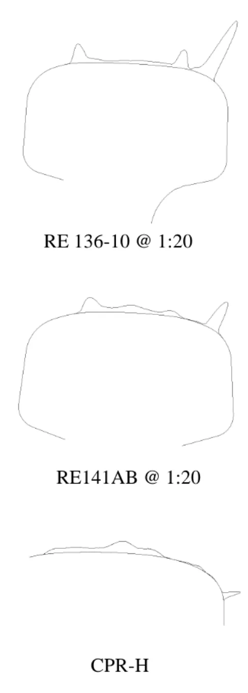
The importance of rail profile and the problem of excessive gage corner loading in high rails has been a major concern in the rail industry. AREMA recently adopted the 141AB rail section as it's new standard for heavy haul operations. The railhead geometry of the 141 is nearly identical (within 0.1 mm) to CPR's current 136 lb/yard 8" rail standard. The CPR profile in turn takes its geometry from the NRC-TT rail grinding template. This design required no grinding in tangent track and significantly less grinding in curves, as compared to the 136 lb/yd RE profile [7]. The 141AB is a substantial improvement over the RE136-10" as a general profile for tangent and curved rail application, especially for an industry that has standardized on the NRC family of 8” rail templates. But as shown by the pummeling distributions in figure 17, the 141AB still sees a concentration of high stress contacts on the gage corner when installed in the high leg of a sharp curve. This results in cracking of the rail lower gage corner of sharp curves (refer to figure 18).
Since CPR installs premium rail only in curves sharper than four and six degrees on main track carrying greater than 50 MGT, and on main track, carrying between 20 and 50 MGT respectively; it may make sense for CPR to purchase all premium
rail with a shape better suited for use in curves. That shape may be close to the CPR-H as shown in figure 19. CPR and NRC plan to explore this possibility in the near future.
Figure 17: Pummeling model of accumulated contact stress. Concentrations of normal stress exist at the gage corner of the RE136-10 and RE141 sections but have been eliminated on the CPR-H.
RE 136-10 @ 1:20
RE141AB @ 1:20
Figure 18: New premium deep head hardend rail installed in 1999 showing gage corner spalling (top figure spalling at 12.5 MGT, bottom figure spalling at 25 MGT).
Figure 19: Alternative premium steel design compared to the AREMA 141 AB profile to reduce gage corner contact stress. (CPR-H is below the 141AB. CPR-L10 is above the 141 AB.)
12.0 Conclusions
CPR has had a well managed preventive rail grinding program for over ten years. CPR suspected that the newer premium steels introduced in the last ten years required less grinding due to improved hardness and wear resistance. CPR had also introduced several rail profile changes which may have influenced their worn wheel profiles: new rail has been manufactured to an eight inch crown since 1996; the low rail of sharp curves has been ground to a flat ten inch crown
radius since 1995, and there were two new NRC tangent profiles implemented in 1997.
In 1999 CPR commissioned NRC to improve their preventive grinding cycles by increasing cycle time from 18 to 25 MGT. The results of the NRC study proved that the newer premium steels in sharp curves were able to withstand the longer grinding cycles. NRC, using their proprietary pummeling model, analyzed typical wheel and rail profiles to design four new rail profiles – two for curves and two for tangent track. In January 2001 these profiles replaced the previous ten NRC/Loram BAR Gage profiles. The new NRC profiles have the following advantages: using four templates greatly simplifies the grinding process; reduced grinding effort; increased grinding production; reduced grinding cost per track mile; increased rail life in curves and tangent track; lower lateral track forces (through better steering overall); increased wheel life; reduced fuel consumption; and reduced hunting of trucks in high speed tangent track. Detail fracture rates are being monitored and have not increased.
CPR left one sharp curve in the test area unground for 150 MGT and verified that rail life was
significantly reduced due to both higher gage face wear on the high rail and severe surface fatigue defects on both high and low rail.
CPR has refined their grinding patterns and expect significant improvements in grinding production with the new NRC rail profiles. CPR expects more
territory to be ground with the same machine and/or a reduction in the grinding budget.
NRC has suggested an improvement to the AREMA 141AB profile for premium rail to reduce sharp curve high rail contact stress that causes gage corner fatigue when new rail is installed. This will allow new rail to be in track longer before it needs to be re-profiled to the optimal NRC designs.
Acknowledgements
The authors wish to acknowledge the excellent support received from: the management and line staff of CPR Shuswap and Thompson Subdivisions; CPR (M. Roney, R. Dashko, M. Sundby), NRC support staff and the Harsco grinding crew.
References
1. Roney M, Lamson S, “Development of Rail Profile Grinding on CP Rail”, Proceedings of the Third International Heavy Haul Conference, Vancouver Canada, June 1986.
2. Roney M, Kalousek J, Sroba P, “Management of Rail Profiles Through Rail Grinding”, Proceedings of the International Heavy Haul Conference, Vancouver Canada, June 1991. 3. Stanford J, Sroba P, Magel E, “Transitioning
from Corrective the Preventive Rail Grinding on the Burlington Northern Santa Fe Railroad", Proceedings of the Seventh International Heavy Haul Conference, Brisbane Australia, June 2001. 4. Roney M, Meyler D,“A Case Study of Wheel /
Rail Cost Reduction on Canadian Pacific Railway’s Coal Route", Proceedings of the Seventh International Heavy Haul Conference, Brisbane Australia, June 2001.
5. DeVries R, “High Speed Production Rail Grinding on Canadian Pacific Railway", Connections 99 Rail Wheel Interface Seminar, Chicago IL, May 1999.
6. Linn S, Abell D, Kalousek J, Sroba P, “Planning of Production Rail Grinding on the Burlington Northern Railway", Proceedings of the Fifth International Heavy haul Conference, Beijing China, June 1993.
7. Kalousek J, Sroba P, Hegelund C, “Analysis of Rail Grinding Tests and Implications for Corrective and Preventive Grinding”, Proceedings of the 4th International Heavy Haul Conference, Brisbane Australia, September 1989.
8. Stanford J, Sroba P, Magel E, “Burlington Northern Santa Fe Preventive-Gradual Grinding Initiative", AREMA, Chicago ILL, September 1999.
9. Sawley K, “Grinding Trial Results on Canadian National and Norfolk Southern Railroads", Technology Digest 98-033, December 1998. 10. Magel E, Kalousek J, “The Application of
Contact Mechanics to Rail/Wheel Profile Design and Rail Grinding”, Proceedings Fifth International Conference on Contact Mechanics and Wear of Wheel/Rail Systems, Tokyo Japan, July 2000.
11. Meyler D, Magel E, Kalousek J, “Reduced Operating Costs Through Improved Wheel Performance on Canadian Pacific Railway”, Proceedings Thirteenth International Wheelset Congress, Rome, September 2001.
12. Magel E, Kalousek J, Sroba P, “Inspection and Analysis of Wheel Profiles Collected from CP Rail” NRC Report Submitted to CPR, November 2000.
13. Transportation Technology Center Inc., “5th Annual Research Review”, Pueblo CO, March 2000.
14. Kalousek J, Sroba, P, “Shuswap Subdivision Rail Samples Metallographic Examination of High and Low Rails from Sharp Curves”, NRC Report Submitted to CPR, November 2000. 15. Magel E, Kalousek J, Sroba P, “CP Rail
Grinding Template Specification”, NRC Report Submitted to CPR, November 2000.
16. Magel E, Caldwell R, Sroba P, “Development of a Crushed Specification for CPR Western Rail Lines”, NRC Report Submitted to CPR, June 2001.
17. Kalousek J, Igwemezie J, “Shell-Like Defects and Microgeometry of Grinding", Proceedings of the International Symposium on: Rail Steels – Developments, Manufacturing and Performance”, Montreal Canada, October 1992. 18. International Heavy Haul Association,
“Guidelines to Best Practices for Heavy Haul Railway Operations: Wheel and Rail Interface Issues”, International Heavy Haul Conference, May 2001.
19. Wierucki W, “Low Rail Analysis, Algoma RE136 lb/yd Rail, Mountain Subdivision”, Internal CPR Report , November 1994.