Part No. P0604218 02
CallPilot 100/150
Installation and Maintenance
Guide
Return
to Menu
2
Copyright © 2003 Nortel Networks
All rights reserved. May 12, 2003.The information in this document is subject to change without notice. The statements, configurations, technical data, and recommendations in this document are believed to be accurate and reliable, but are presented without express or implied warranty. Users must take full responsibility for their applications of any products specified in this document. The information in this document is proprietary to Nortel Networks NA Inc.
Trademarks
NORTEL NETWORKS is a trademark of Nortel Networks.
All other trademarks and registered trademarks are the property of their respective owners.
Statement of conditions
In the interest of improving internal design, operational function, and/or reliability, Nortel Networks NA Inc. reserves the rig ht to make changes to the products described in this document without notice.
Nortel Networks NA Inc. does not assume any liability that may occur due to the use or application of the product(s) or circuit layout(s) described herein.
Regulatory Requirements
CallPilot 100/150 meets CSPR22 Class A regulatory requirements. FCC Regulations
This equipment complies with Federal Communications Commission Rules and Regulations Part 68 when connected to a Norstar switch. This equipment does not connect directly to the public switched telephone network.
DOC Regulations
This equipment complies with the Canadian Department of Commerce CS-03 Rules and Regulations for connection to Norstar switches.
Radio Frequency Interference
This equipment generates, uses and can radiate radio frequency energy and if not installed and used in accordance with the instruction manual may cause interference to radio communications. It has been tested and found to comply with the limits for a Class A computing device pursuant to Part 15 of the FCC Rules and CSDA specification C108.8, which are designed to provide reasonable protection against such interference when operated in a commercial environment. Operation of this equipment in a residential area is likely to cause interference, in which case users will be required, at their own expense, to take whatever measures are necessary to correct the interference.
This apparatus does not exceed the Class A limits for radio noise emissions from digital apparatus set out in the Radio Interference Regulations by the Canadian Department of Commerce.
3
Contents
Preface . . . 11Before you begin . . . 11
Text conventions . . . 11
About the buttons on your telephone . . . 12
Related publications . . . 12
How to Get Help . . . 13
USA and Canada . . . 13
Authorized Distributors - ITAS Technical Support . . . 13
Presales Support (CSAN) . . . 13
EMEA (Europe, Middle East, Africa) . . . 13
Technical Support - CTAS . . . 13
CALA (Caribbean & Latin America) . . . 14
Technical Support - CTAS . . . 14
APAC (Asia Pacific) . . . 14
Technical Support - CTAS . . . 14
Chapter 1 How to use this guide . . . 15
How to use this guide . . . 15
How the instructions are presented . . . 16
Warning and caution symbols . . . 16
Chapter 2 System overview . . . 17 About CallPilot 100/150 . . . . 17 CallPilot 100/150 offers . . . 17 Features of CallPilot . . . 17 Compatibility . . . 18 Hardware overview . . . 18 Data connectors . . . 18 PCMCIA slots . . . 19 Dimensions . . . 19
4
Managing the CallPilot system . . . 22
Running without a LAN . . . 22
Using a LAN . . . 22
DNS server . . . . 22
Chapter 4 Installing CallPilot 100/150 . . . 23
Wall mounting the CallPilot 100/150 . . . 23
Connecting the CallPilot 100/150 . . . 24
CallPilot 100/150 LEDs . . . . 26
Chapter 5 Initializing the CallPilot 100/150 . . . 29
About CallPilot Manager . . . 29
Initializing CallPilot 100/150 using CallPilot Manager . . . 30
Computer requirements for CallPilot Manager . . . 30
Computer requirements . . . 30
Browser requirements . . . 30
Connecting to the CallPilot 100/150 . . . 31
Changing the IP address using a serial cable . . . 31
Changing the IP address using an Ethernet crossover cable . . . 34
Running the Quick Install Wizard . . . 35
Initializing CallPilot 100/150 using a telephone . . . 38
Determining CallPilot 100/150 Feature Codes . . . 38
Configuring the CallPilot 100/150 initial parameters . . . 39
Chapter 6 Language Configuration Utility. . . 43
Changing the languages available . . . 43
Chapter 7 Password administration. . . 45
Resetting passwords . . . . 45
Resetting the system administrator password . . . 45
5
Chapter 8 Backing up and restoring CallPilot . . . 51
Installing the CallPilot Backup and Restore Utility . . . 51
Backing up the CallPilot information . . . 51
Restoring the CallPilot information . . . 53
Retrieving the CallPilot log files . . . 55
Chapter 9 Upgrading CallPilot 100/150 . . . 57
Upgrading the CallPilot software version . . . 57
Upgrading the message storage . . . 58
Chapter 10 Troubleshooting . . . 61
Introduction . . . 61
Diagnosing problems . . . . 61
The RS-232 terminal cannot communicate with CallPilot 100/150 . . . 61
CallPilot 100/150 does not function at all . . . 62
The Power-on Diagnostics fail . . . 63
Cannot access CallPilot Manager . . . 63
CallPilot 100/150 fails during a start up . . . 63
All of the mailboxes disappear after a software upgrade . . . 63
CallPilot 100/150 Feature Codes are inactive . . . 64
To remove Feature Codes . . . 64
CallPilot 100/150 does not reboot following **STARTUP . . . 65
Inactive feature . . . . 65
Time on the CallPilot 100/150 does not match the time on the telephone system . . . 66
LED error messages . . . 66
LED 1 is blinking quickly . . . 66
LED 1 and LED 2 are blinking quickly . . . 66
LEDs 1 to 4 turn on at power up but do not briefly turn off during start up . . . 66
One or more of LEDs 1 to 4 do not turn on after CallPilot 100/150 has finished starting up . . . 66
6
Creating a Dial-Up Networking connection on Windows NT 4.0 . . . 69
Configuring the Dial-Up Networking TCP/IP parameters on Windows NT 4.0 . . . 70
Creating a Dial-Up Networking connection on Windows 2000 or Windows XP . . . . 71
Configuring the Dial-Up Networking TCP/IP parameters on Windows 2000 or Windows XP . . . 71
Installing the Nortel Networks Modem Configuration Utility . . . 72
Enabling the CallPilot modem . . . 73
Enabling Modem access using CallPilot Manager . . . 73
Enabling Modem access using a telephone . . . 73
Changing the modem access password using a telephone . . . 74
Disabling the Modem access password using a telephone . . . 74
Connecting to the CallPilot system . . . 75
Configuring your modem to access the CallPilot modem . . . 75
Connecting to the CallPilot modem . . . 75
Configuring your modem for normal modem connections . . . 77
Appendix B Norstar Directory Numbers . . . 79
Programming CallPilot 100/150 DNs to memory buttons . . . 80
Glossary . . . 81
7
Figures
Figure 1 Inside the CallPilot 100/150 . . . 19Figure 2 Mounting the CallPilot 100/150 . . . 23
Figure 3 CallPilot 100/150 connections . . . 25
9
Tables
Table 1 Telephone buttons . . . 12Table 2 CallPilot features . . . 17
Table 3 Compatible Norstar KSU systems . . . 18
Table 4 Port A and Port B Pinouts . . . 24
Table 5 LEDs during startup . . . 26
Table 6 LEDs during operation . . . 27
Table 7 CallPilot 100/150 serial port pinout . . . 31
Table 8 Quick Install Wizard parameters for a CallPilot 100/150 . . . 35
Table 9 Assigned Feature Codes . . . 38
Table 10 Maximum disk space required to backup CallPilot 100/150 . . . 52
Table 11 Non-expanded Modular ICS DNs . . . 79
Table 12 Modular ICS 2-port cartridge DNs . . . 79
11
Preface
The CallPilot 100/150 is a voice messaging product suited for small to medium sized businesses. It combines the voicemail and call processing features of a large business system into a compact, easy to use system.
Before you begin
This guide is intended for install technicians. This guide assumes that you have a working knowledge of the telephone system on which you are installing the CallPilot 100/150.
Text conventions
This guide uses the following text conventions:
angle brackets (< >) Indicate that you choose the text to enter based on the description inside the brackets. Do not type the brackets when entering the command. Example: If the command syntax is
ping<ip_address>, you enter ping 192.32.10.12
bold Courier text Indicates command names and options and text that you need to enter. Example: Use the dinfo command.
Example: Enter show ip{alerts|routes}.
italic text Indicates book titles.
Example: CallPilot Manager Set Up and Operation Guide plain Courier
text
Indicates command syntax and system output, for example, prompts and system messages.
Example: Set Trap Monitor Filters
ıËÊÊ‚ˆÍ Indicates the buttons you press on a telephone. Example: ≤·°‹
Display font Indicates text prompts that appear on the telephone display. Example: Group lists? Y
Underlined display font
Indicates a label that appears above the display button. You press the button below this label to perform the action.
12 Preface
About the buttons on your telephone
This guide shows the Business Series Terminal buttons. Table 1 shows which buttons to use on the different types of Nortel Networks telephones.
You can enter ≤, ƒ or ƒ and the code to use a feature. For example: Press
≤·°⁄ to access your mailbox.
The T7100 works differently from other telephones on your system because it does not have line buttons. Where other telephones can require that you select a line button to answer a call, with the T7100 terminal you pick up the handset. Where other telephones require you to select a line button to take a call off hold, you press ≥ on the T7100 terminal.
On T7100 terminals, you can answer a second call by pressing ˙. Your active call is put on hold and you connect to the waiting call. You can have no more than two active calls at one time.
The T7100 terminal does not have a © button.
Related publications
For more information about programming CallPilot 100/150, refer to the following publications: • CallPilot Manager Set Up and Operation Guide
Provides instructions for setting up the CallPilot 100/150 using CallPilot Manager. • CallPilot 100/150 Telephone Administration Guide
Provides instructions for setting up the CallPilot 100/150 using a Norstar telephone. • CallPilot Programming Record
Table 1 Telephone buttons
Button Name T7100, T7208, T7316, T7316E M7100, M7208, M7310, M7324 M7100N, M7208N, M7310N, M7324N Feature ≤ ƒ ƒ Hold ≥˙
≥
˙≥
˙ Volume Control √ √ √ Release ® ® ®Preface 13
How to Get Help
USA and Canada
Authorized Distributors - ITAS Technical Support
Telephone:
1-800-4NORTEL (1-800-466-7835)
If you already have a PIN Code, you can enter Express Routing Code (ERC) 196#.
If you do not yet have a PIN Code, or for general questions and first line support, you can enter ERC 338#.
Website:
http://www.nortelnetworks.com/itas/
Presales Support (CSAN)
Telephone:
1-800-4NORTEL (1-800-466-7835)
Use Express Routing Code (ERC) 1063#
EMEA (Europe, Middle East, Africa)
Technical Support - CTAS
Telephone:
00800 800 89009 or 33 4 9296 1341
14 Preface
CALA (Caribbean & Latin America)
Technical Support - CTAS
Telephone:
1-954-858-7777
email:
APAC (Asia Pacific)
Technical Support - CTAS
Telephone:
+61 388664627Fax:
+61 388664644email:
[email protected]15
Chapter 1
How to use this guide
This guide explains:
• what CallPilot 100/150 is • how to install CallPilot 100/150 • how to initialize CallPilot 100/150 • how to troubleshoot CallPilot 100/150
How to use this guide
Chapter 1, “How to use this guide explains the contents of this guide and the conventions it uses.
Chapter 2, “System overview provides a functional overview of the CallPilot 100/150.
Chapter 3, “Preparing to install the CallPilot 100/150 describes what is required before you install the CallPilot 100/150.
Chapter 4, “Installing CallPilot 100/150 describes how to install the CallPilot 100/150.
Chapter 5, “Initializing the CallPilot 100/150 describes how to program the initial parameters for the CallPilot 100/150.
Chapter 6, “Language Configuration Utility describes how to change the languages available on the CallPilot 100/150.
Chapter 7, “Password administration describes how to reset the passwords on CallPilot 100/150.
Chapter 8, “Backing up and restoring CallPilot describes how to back up and restore CallPilot information.
Chapter 9, “Upgrading CallPilot 100/150 describes how to upgrade CallPilot 100/150.
Chapter 10, “Troubleshooting describes problems, error messages and corrective actions.
16 Chapter 1 How to use this guide
How the instructions are presented
The tasks in this book are presented as step-by-step instructions, in the order you must carry them out.
Warning and caution symbols
Sometimes you will see symbols warning you to be careful. These symbols include:
Before you begin any task, read all the steps, including Notes, Cautions, and Warnings.
Note: alerts you to steps that are complicated or critical.
Caution:
alerts you to situations where you may damage the equipment.
17
Chapter 2
System overview
About CallPilot 100/150
The CallPilot 100/150 is a voice messaging product suited for small to medium sized businesses. It combines the voicemail and call processing features of a large business system into a compact, easy to use system.
CallPilot 100/150 offers
• connection to a compatible Norstar telephone system
• voicemail with a choice of a CallPilot or Norstar Voice Mail interface • up to eight voice channels
• Call Center functionality
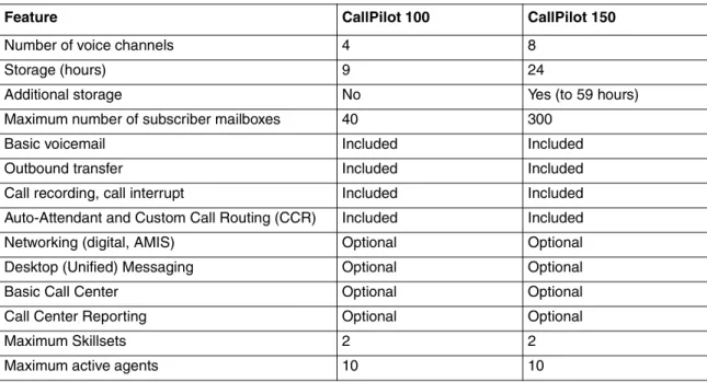
Features of CallPilot
Table 2 CallPilot features
Feature CallPilot 100 CallPilot 150
Number of voice channels 4 8
Storage (hours) 9 24
Additional storage No Yes (to 59 hours)
Maximum number of subscriber mailboxes 40 300
Basic voicemail Included Included
Outbound transfer Included Included
Call recording, call interrupt Included Included
Auto-Attendant and Custom Call Routing (CCR) Included Included
Networking (digital, AMIS) Optional Optional
Desktop (Unified) Messaging Optional Optional
Basic Call Center Optional Optional
18 Chapter 2 System overview
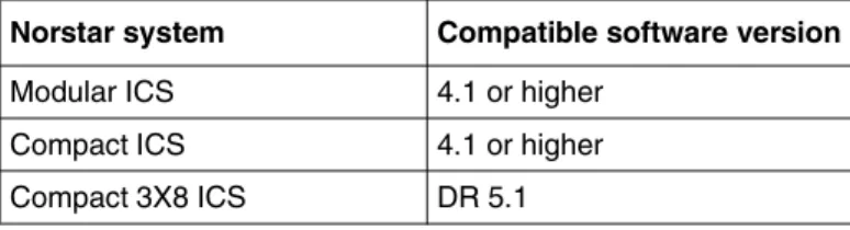
Compatibility
The CallPilot 100/150 can connect to these Norstar telephone systems:
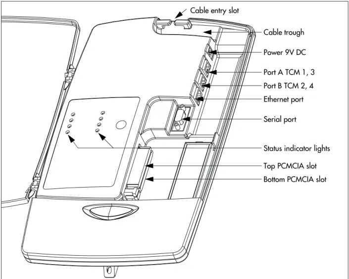
Hardware overview
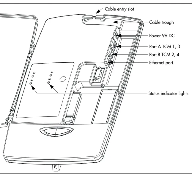
The CallPilot 100/150 is a compact device that you can mount on a desk or on the wall.
Figure 1 points out the various parts of the CallPilot hardware.
Data connectors
The CallPilot 100/150 has the following connections:
• one RJ-45 jack for a 10/100 Mbps Ethernet connection to a local network
Table 3 Compatible Norstar KSU systems
Norstar system Compatible software version
Modular ICS 4.1 or higher
Compact ICS 4.1 or higher
Compact 3X8 ICS DR 5.1
Note: The Compact 3X8 ICS works with the CallPilot 100 only.
The Park and Page and AMIS Networking features are not available when the CallPilot 100 is connected to a Compact 3X8 ICS.
Note: CallPilot 100/150 does not work with Centrex KSUs.
Chapter 2 System overview 19 Figure 1 Inside the CallPilot 100/150
PCMCIA slots
The CallPilot 100/150 has two PCMCIA slots.
• The bottom slot is used for the feature cartridge. The feature cartridge is the device that stores the CallPilot software, greetings and voice messages.
• The top slot is used during software upgrades.
Cable trough Power 9V DC Port A TCM 1, 3 Port B TCM 2, 4 Ethernet port Serial port
Top PCMCIA slot Bottom PCMCIA slot Cable entry slot
20 Chapter 2 System overview
Voice message storage
The voice message storage is the amount of memory that CallPilot 100/150/CallPilot 100 has to store greetings and voicemail messages.
The CallPilot 100 provides 9 hours of voice message storage.
The CallPilot 150 provides 24 hours of voice message storage. With the optional message storage upgrade, the CallPilot 150 provides 59 hours of voice message storage.
Power
An external power supply provides 9V DC for the CallPilot 100/150. Use only the power supply that is provided with the CallPilot 100/150.
21
Chapter 3
Preparing to install the CallPilot 100/150
This chapter explains what you need before you install the CallPilot 100/150.
Environment
Make sure the installation area is:
• clean, free of dust, dry and well ventilated • between 0 and 50 degrees Celsius
• non-condensing relative humidity between 5 percent and 95 percent
• at least 4 m, or 13 ft., from any equipment that could produce electromagnetic, radio frequency and electrostatic interference
• a wall area about 1 m (3 ft.) square
• closer than 15 m, or 50 ft., of cable length from the Norstar KSU • within 1.5 m, or about 5 ft., of a three-wire grounded electrical outlet • a minimum of 16 cm, or 6 in., from a corner wall or other component • a minimum of 46 cm, about 18 in., from the floor, to prevent water damage
Electrical service
Make sure the power is:
• 115/230 VAC nominal; range 100 to 240 V • 50/60 Hz nominal; range 47 to 63 Hz • Third-wire ground
• Unswitched
Opening the kit
22 Chapter 3 Preparing to install the CallPilot 100/150
Managing the CallPilot system
CallPilot 100/150 is managed using a telephone or CallPilot Manager, depending on whether the CallPilot 100/150 has a LAN connection.
Running without a LAN
A LAN connection is optional for a basic CallPilot 100/150 system running on a Norstar system. When there is no LAN connection, you can administer the system through a telephone using the
≤·°‹ menus.
Using a LAN
When there is a LAN connection, CallPilot 100/150is managed through a web browser interface called CallPilot Manager.
To use CallPilot Manager, the CallPilot 100/150 system must have a fixed IP address.
All CallPilot 100/150 systems are shipped with the default IP address of 192.168.110.10. If this IP address conflicts with your network, you must change the address before connecting the CallPilot 100/150 to your network. You can change the IP address using a terminal connected to the CallPilot 100/150 serial port, or through a temporary Ethernet connection using an Ethernet crossover cable to a stand alone computer or laptop.
Detailed instructions for setting the IP address and accessing CallPilot Manager are provided in
“Initializing the CallPilot 100/150” on page 29.
DNS server
Your LAN does not require a DNS server for CallPilot 100/150 to operate. However, a DNS server provides an easier interface to accessing the CallPilot Manager URL by providing a
language-based name, such as CallPilot01. After this name is added to the DNS server as an alias for the system IP address, users can start CallPilot Manager by entering this name.
Note: You require a LAN connection to print reports, administer the Networking feature, use the Backup and Restore Utility and use the Language Configuration Utility.
23
Chapter 4
Installing CallPilot 100/150
This chapter describes installing the CallPilot 100/150 on a wall and powering it up.
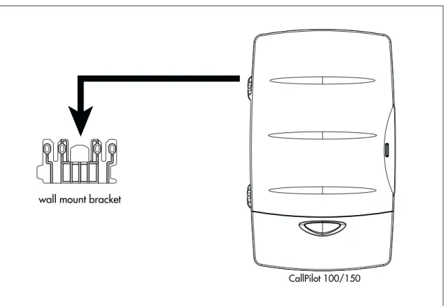
Wall mounting the CallPilot 100/150
Follow this procedure to mount the CallPilot 100/150 on a wall.
1 Attach the wall mount bracket to a secure surface by the two inner holes. Use anchors, as necessary.
2 Slip the slot on the back (near the top) of the CallPilot 100/150onto the bracket.
3 Secure the CallPilot 100/150using a screw in the lower screw hole.
Figure 2 Mounting the CallPilot 100/150
wall mount bracket
24 Chapter 4 Installing CallPilot 100/150
Connecting the CallPilot 100/150
1 Open the CallPilot 100/150by inserting a flat screwdriver into the slot on the right-hand side of the door and pressing the tab out of the way.
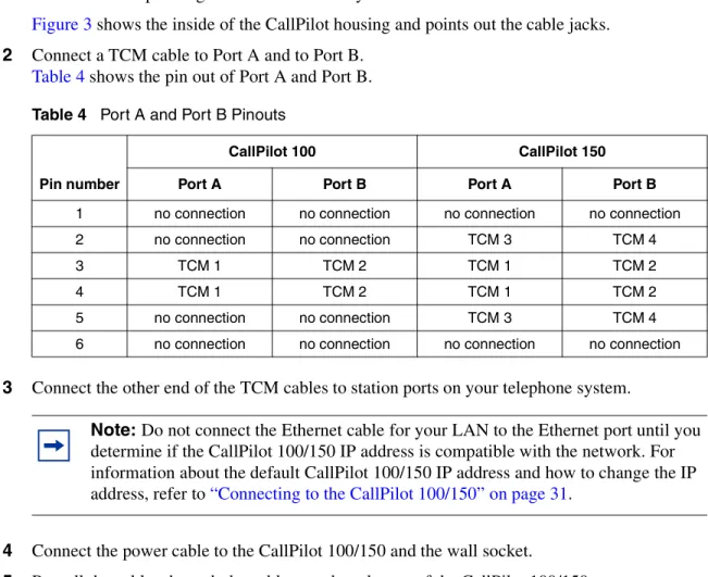
Figure 3 shows the inside of the CallPilot housing and points out the cable jacks.
2 Connect a TCM cable to Port A and to Port B.
Table 4 shows the pin out of Port A and Port B.
3 Connect the other end of the TCM cables to station ports on your telephone system.
4 Connect the power cable to the CallPilot 100/150and the wall socket.
5 Run all the cables through the cable trough at the top of the CallPilot 100/150.
6 Close the lid.
Table 4 Port A and Port B Pinouts
Pin number
CallPilot 100 CallPilot 150 Port A Port B Port A Port B
1 no connection no connection no connection no connection
2 no connection no connection TCM 3 TCM 4
3 TCM 1 TCM 2 TCM 1 TCM 2
4 TCM 1 TCM 2 TCM 1 TCM 2
5 no connection no connection TCM 3 TCM 4
6 no connection no connection no connection no connection
Note: Do not connect the Ethernet cable for your LAN to the Ethernet port until you determine if the CallPilot 100/150 IP address is compatible with the network. For information about the default CallPilot 100/150 IP address and how to change the IP address, refer to “Connecting to the CallPilot 100/150” on page 31.
Chapter 4 Installing CallPilot 100/150 25 Figure 3 CallPilot 100/150 connections
Cable trough Power 9V DC Port A TCM 1, 3 Port B TCM 2, 4 Ethernet port Cable entry slot
26 Chapter 4 Installing CallPilot 100/150
CallPilot 100/150 LEDs
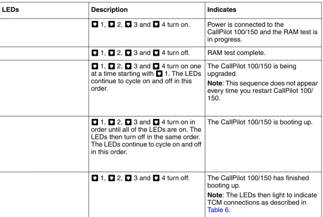
When the CallPilot 100/150 starts up, the LEDs change to indicate where the CallPilot 100/150 is in the start up process. Table 5 shows the order in which the LEDs change and describes what each state indicates.
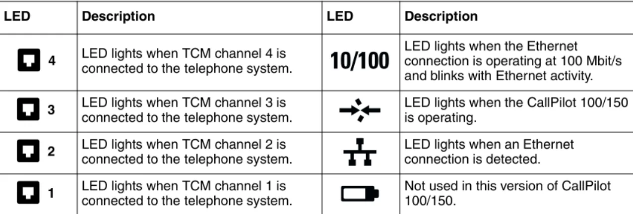
When the CallPilot 100/150 is operating, the LEDs indicate the operating status of the CallPilot interfaces. Table 6 describes the purpose of the LEDs.
Table 5 LEDs during startup
LEDs Description Indicates
1, 2, 3 and 4 turn on. Power is connected to the
CallPilot 100/150 and the RAM test is in progress.
1, 2, 3 and 4 turn off. RAM test complete. 1, 2, 3 and 4 turn on one
at a time starting with 1. The LEDs continue to cycle on and off in this order.
The CallPilot 100/150 is being upgraded.
Note: This sequence does not appear every time you restart CallPilot 100/ 150.
1, 2, 3 and 4 turn on in order until all of the LEDs are on. The LEDs then turn off in the same order. The LEDs continue to cycle on and off in this order.
The CallPilot 100/150 is booting up.
1, 2, 3 and 4 turn off. The CallPilot 100/150 has finished booting up.
Note: The LEDs then light to indicate TCM connections as described in Table 6.
Chapter 4 Installing CallPilot 100/150 27
Table 6 LEDs during operation
LED Description LED Description
LED lights when TCM channel 4 is connected to the telephone system.
LED lights when the Ethernet connection is operating at 100 Mbit/s and blinks with Ethernet activity. LED lights when TCM channel 3 is
connected to the telephone system.
LED lights when the CallPilot 100/150 is operating.
LED lights when TCM channel 2 is connected to the telephone system.
LED lights when an Ethernet connection is detected. LED lights when TCM channel 1 is
connected to the telephone system.
Not used in this version of CallPilot 100/150.
Note: If the LAN interface is disabled with you startup CallPilot 100/150, the LED lights immediately, not after the CallPilot 100/150 is operating.
4
3
2
29
Chapter 5
Initializing the CallPilot 100/150
After you install and power up the CallPilot 100/150, you need to initialize it. Initializing the CallPilot 100/150 sets the system parameters to their default settings and sets some global parameters. When the initialization is completed, the CallPilot 100/150 is operational and ready for you to begin administration programming. Refer to “Related publications” on page 12 for a list of documents that provide information about administration programming.
You initialize CallPilot 100/150using CallPilot Manager or a telephone.
About CallPilot Manager
CallPilot Manager is an application that you access from a web browser, such as Netscape®
Communicator1 or Microsoft® Internet Explorer2. Nortel Networks recommends you use CallPilot
Manager whenever possible. CallPilot Manager provides access to administration programming not available from a telephone.
To use CallPilot Manager, you must have a network connection to the CallPilot 100/150 or an Ethernet crossover cable. If you are using CallPilot Manager to initialize CallPilot 100/150, refer to “Initializing CallPilot 100/150 using CallPilot Manager” on page 30.
If you do not have a network connection or an Ethernet crossover cable, you can initialize the CallPilot 100/150 using a two-line display telephone. If you are using a telephone to initialize CallPilot 100/150, refer to “Initializing CallPilot 100/150 using a telephone” on page 38.
Note: Upgrading to CallPilot 100/150from a previous voice messaging system.
If you are upgrading from a previous voice messaging system (for example, FlashTalk) to CallPilot 100/150, you must remove the existing Feature Codes for the old voice
messaging system before you configure CallPilot 100/150. For information about how to remove the existing Feature Codes, refer to “To remove Feature Codes” on page 64.
Note: The online Help for CallPilot Manager is best viewed in Internet Explorer. There can be some page format inconsistencies if you use other browsers.
30 Chapter 5 Initializing the CallPilot 100/150
Initializing CallPilot 100/150 using CallPilot Manager
To initialize CallPilot 100/150 using CallPilot Manager you need to:
• determine if your computer meets the CallPilot Manager requirements • connect to the CallPilot 100/150
• run the Quick Install Wizard
Computer requirements for CallPilot Manager
You access CallPilot Manager using a web browser on a computer that is connected to the CallPilot 100/150.
Computer requirements
The computer you use to access CallPilot Manager must be compatible with Microsoft® Windows®
and capable of running your web browser.
Browser requirements
To use CallPilot Manager, you must have one of the following browsers:
• Netscape Communicator 4.5 or later • Microsoft Internet Explorer 4.0 or later
Chapter 5 Initializing the CallPilot 100/150 31
Connecting to the CallPilot 100/150
To connect to the CallPilot 100/150/CallPilot 100, you need the IP address of the CallPilot 100/150 and a connection to the network that the CallPilot 100/150 is on.
The default IP address for CallPilot 100/150 is 192.168.110.10.
If the default IP address is compatible with your network, you can connect the LAN cable to the Ethernet port on the CallPilot 100/150 and proceed to “Running the Quick Install Wizard” on page 35.
If the default IP address is not compatible, you must change the IP address before you connect the CallPilot 100/150 to the network. You can change the IP address using a serial cable or an Ethernet crossover cable (direct PC connection).
Changing the IP address using a serial cable
If you are going to change the IP address using a serial cable, you need a:
• serial cable
• VT100-compatible terminal or a computer that has a VT100 compatible terminal emulation program such as HyperTerminal
CallPilot 100/150 serial port
The following table shows the pin out for the CallPilot 100/150 serial port.
Note: If you are unsure if the default IP address is compatible, contact your network administrator.
Note: The serial port is intended for temporary connections only. After you have finished changing the IP address, remove the serial cable and close the CallPilot 100/150 door. Failure to remove the serial cable may result in a non-compliant EMC configuration.
Note: A serial cable is available as a separately available part. For information about obtaining a serial cable, contact your Nortel Networks supplier.
32 Chapter 5 Initializing the CallPilot 100/150
Configuring the terminal
The terminal or terminal emulation program you use must be VT100 compatible and must support the ASCII Character set. If the terminal does not support the ASCII Character set, the text displays incorrectly.
You must configure your terminal to the following communications parameters: • 9600 bits per second
• 8 data bits • no parity • 1 stop bit • no flow control
For information about how to set these parameters, refer to the documentation for your terminal or terminal emulation program.
Changing the IP address using the terminal
To change the IP address:
1 Attach the serial cable to the serial port on the CallPilot 100/150. For information about the location of the serial port, refer to Figure 3 on page 25.
2 Attach the other end of the cable to the serial port on the terminal or computer.
3 Ensure that your terminal or computer is powered up.
4 If you are using a computer, start your terminal emulation program.
5 Remove power from the CallPilot 100/150.
6 Reconnect power to the CallPilot 100/150.
Note: The location of the transmit (TX) and receive (RX) pins on your terminal can vary. Refer to your terminal or computer documentation to confirm pin locations.
Note: Steps 5 and 6 are used to force the CallPilot 100/150 to reboot. You can change the IP address only while the CallPilot 100/150 is booting up.
Chapter 5 Initializing the CallPilot 100/150 33 7 Press the Enter key.
The prompt (M)odify any of this or (C)ontinue? appears.
8 Press the M key and press the Enter key.
The prompt Do you want a LAN interface? appears.
9 Press the Y key and press the Enter key.
The prompt This board’s LAN IP Address (0.0.0.0 = RARP) appears.
10 Type the IP address for the CallPilot 100/150 in a valid dotted format and press the Enter key. The prompt Subnet mask for LAN (0 for none) appears.
11 Type the Subnet Mask for the CallPilot 100/150 in a valid dotted format and press the Enter
key.
The prompt Should there be a default gateway for packet routing? appears.
12 If the CallPilot 100/150 needs a next hop router, press the Y key and press the Enter key. If the CallPilot 100/150 does not need a next hop router, press the N key, press the Enter key and go to step 15.
The prompt IP address of default gateway? appears.
13 Type the IP address of the next hop router in a valid dotted format and press the Enter key.
14 Press the Enter key until the following prompt appears. (M)odify any of this or (C)ontinue?
15 Press the C key and press the Enter key.
16 Connect the LAN cable to the Ethernet port on the CallPilot 100/150.
You can now initialize the CallPilot parameters. For information about how to initialize the CallPilot , refer to “Running the Quick Install Wizard” on page 35.
Note: If you do not press a key within 2 seconds of this prompt appearing, repeat steps 5 and 6.
34 Chapter 5 Initializing the CallPilot 100/150
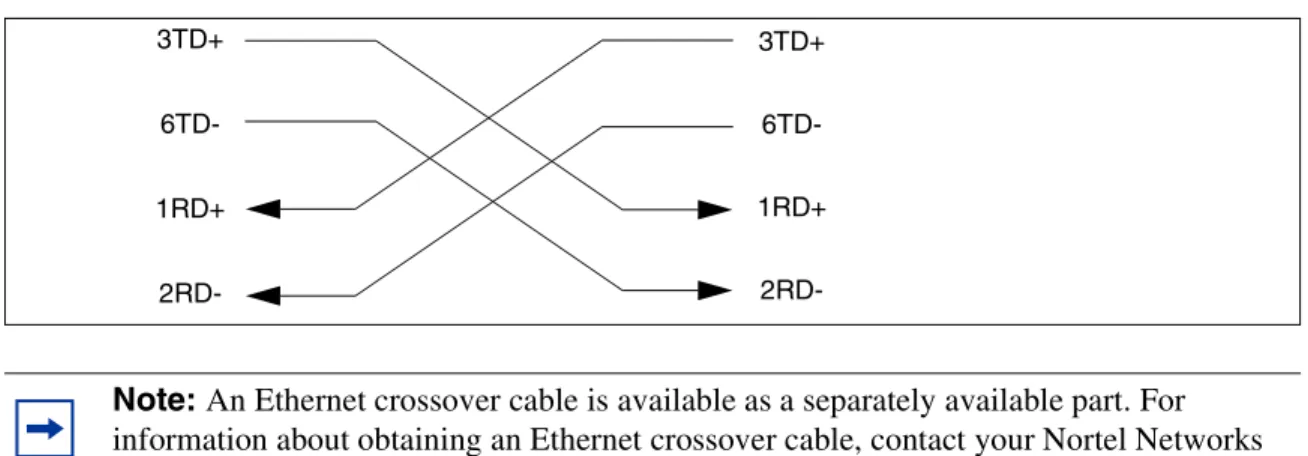
Changing the IP address using an Ethernet crossover cable
Using an Ethernet crossover cable, you can connect the CallPilot 100/150 to your computer. With this connection, you can use CallPilot Manager to change the CallPilot 100/150 IP address before you connect it to the network.
To use an Ethernet crossover cable, your computer must be equipped with a 10/100 BaseT Ethernet card and support TCP/IP protocol. Figure 4 shows the connections required.
Figure 4 Ethernet crossover cable
Connecting the Ethernet crossover cable
1 Shut down the computer.
2 Attach one end of the Ethernet crossover cable to the Ethernet port on the CallPilot 100/150.
3 Connect the other end of the cable to the network interface card on your computer.
4 Start the computer.
5 Use the Quick Install Wizard to initialize the CallPilot 100/150.
For information about how to use the Quick Install Wizard, refer to “Running the Quick Install Wizard” on page 35.
Note: If you do not have access to the CallPilot 100/150 through the network, you can use an Ethernet crossover cable to configure all of the CallPilot 100/150 parameters.
Note: An Ethernet crossover cable is available as a separately available part. For information about obtaining an Ethernet crossover cable, contact your Nortel Networks supplier. 3TD+ 6TD-1RD+ 2RD-3TD+ 6TD-1RD+
2RD-Chapter 5 Initializing the CallPilot 100/150 35
Running the Quick Install Wizard
The Quick Install Wizard appears the first time you startup CallPilot Manager. The Quick Install Wizard is a single page that gathers enough information to set up a working system. It then applies the information and restarts the system.
You can reach CallPilot Manager from another computer through a LAN connection, WAN/ Internet connection or an Ethernet crossover cable. All of these methods create an IP connection that allows you to run CallPilot Manager.
Use the following procedure to run the Quick Install Wizard:
1 Launch your browser.
2 In the URL address box, type the CallPilot 100/150 IP address. For example: HTTP://192.168.110.10
The Quick Install Wizard screen appears. Depending on your system, this can take several minutes to appear.
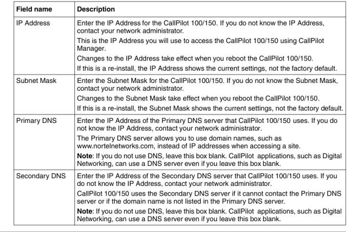
3 Configure the Quick Install parameters for a CallPilot 100/150 according to Table 8 on page 35.
Table 8 Quick Install Wizard parameters for a CallPilot 100/150
Note: You must include HTTP:// to access CallPilot Manager.
Field name Description
IP Address Enter the IP Address for the CallPilot 100/150. If you do not know the IP Address, contact your network administrator.
This is the IP Address you will use to access the CallPilot 100/150 using CallPilot Manager.
Changes to the IP Address take effect when you reboot the CallPilot 100/150. If this is a re-install, the IP Address shows the current settings, not the factory default. Subnet Mask Enter the Subnet Mask for the CallPilot 100/150. If you do not know the Subnet Mask,
contact your network administrator.
Changes to the Subnet Mask take effect when you reboot the CallPilot 100/150. If this is a re-install, the Subnet Mask shows the current settings, not the factory default. Primary DNS Enter the IP Address of the Primary DNS server that CallPilot 100/150 uses. If you do
36 Chapter 5 Initializing the CallPilot 100/150
Default Gateway Enter the IP Address of the default next-hop router. If you do not know the IP Address, contact your network administrator.
Note: If you do not require a next-hop router, leave this box blank.
Base Application The default base application is voicemail. If you want the base application to be Call Center, click the CallCenter button.
If you select voicemail:
• the voicemail application is enabled
• 20 mailboxes are enabled on the CallPilot 150 • 10 mailboxes are enabled on the CallPilot 100.
If you select Call Center: • no mailboxes are enabled
• the Call Center application is enabled • 20 agents are enabled (10 agents are active)
• the mailbox and lines administration sections are removed from the Quick Install Wizard screen.
Attendant DN Enter the extension number of the CallPilot attendant.
Primary UI Style Select the user interface style assigned to the mailboxes. You can select NVM or CallPilot.
If you select NVM, the mailbox user interface operates like Norstar Voice Mail and FlashTalk. Users will hear Norstar Voice Mail voice prompts and see Norstar Voice Mail text prompts.
If you select CallPilot, the mailbox user interface operates like Meridian 1 CallPilot. Users will hear CallPilot voice prompts and see text prompts for CallPilot.
You can change the UI style of individual mailboxes by assigning a different Class of Service to those mailboxes.
Primary Language
Select the default language that is used for voice prompts, text messages, the Auto-Attendant and Feature 983 administration.
You can change the language of individual mailboxes by assigning a different Class of Service to those mailboxes.
Country Select the country in which the CallPilot 100/150 is installed.
The country you select determines several country specific settings such as the telephone number length, mailbox login sequence and Call Progress Tone Detection. You must select the country that the CallPilot 100/150 is in to ensure proper operation. The default is North America.
From Line Enter the line number of the first line in a range of lines that you want the auto-attendant to answer.
Chapter 5 Initializing the CallPilot 100/150 37
4 Click the Install button.
You can now start programming the CallPilot parameters. For information about how to program CallPilot , refer to the CallPilot Manager Set Up and Operation Guide.
Mailbox Keycode If you have purchased additional mailboxes for CallPilot , enter the keycode you received with your mailbox package.
If you have not purchased additional mailboxes, leave these boxes empty.
Use these boxes only for the keycode for additional mailboxes. Do not enter the keycode that enables the basic voicemail application.
From Extension Enter the extension number of the first telephone in a range of telephones you want to create a mailbox for.
A mailbox is created for this telephone and for all of the telephones up to the extension number you enter in the To Extension box.
The mailboxes are named according the set name of the telephone and assigned Class of Service 1.
To Extension Enter the extension number of the last telephone in a range of telephones you want to create a mailbox for.
The extension number you enter in this box must be the same or higher than the extension number you enter in the From Extension box.
Outdial Method Select the outdial method you want to assign to the mailboxes created using the From Extension and To Extension boxes. You can choose None, Line, Pool or Route. If you select None, no outdial method is assigned to the mailboxes.
If you select Line, click the Outdial Method text box and enter the line number of the line you want assign to the mailboxes.
If you select Pool, click the Outdial Method text box and enter the line pool number of the line pool you want to assign to the mailboxes.
Note: Line pool numbers 0 to 15 correspond to the Line Pools A to O on the KSU programming interface.
If you select Route, click the Outdial Method text box and enter the route number of the route you want to assign to the mailboxes.
Note: If you have changed any of the IP addresses or the Subnet Mask, you must reboot the CallPilot 100/150 before you start programming the CallPilot parameters.
38 Chapter 5 Initializing the CallPilot 100/150
Initializing CallPilot 100/150 using a telephone
To initialize CallPilot 100/150 you need to:
• determine the CallPilot 100/150 Feature Codes • configure the CallPilot 100/150 initial parameters
Determining CallPilot 100/150 Feature Codes
Default Feature Codes are assigned to CallPilot 100/150by the Norstar system. These default codes are listed in Table 9. When these default Feature Codes are used by other Norstar
applications, the Norstar system assigns Feature Codes between 900 and 999 to CallPilot 100/150. These codes might not be assigned in sequential order. Record the assigned Feature Codes on
Table 9.
Table 9 Assigned Feature Codes
Note: If you initialized CallPilot 100/150 using CallPilot Manager, you do not need to initialize CallPilot 100/150 using a telephone.
Feature Code name Default Number Used By
Agent Login ≤·‚› ≤· _____ _____ Call Center only
Busy Mode ≤·‚° ≤· _____ _____ Call Center only
Queue Status ≤·‚· ≤· _____ _____ Call Center only
Leave Message ≤·°‚ ≤· _____ _____ Call Center and Voicemail
Open Mailbox ≤·°⁄ ≤· _____ _____ Call Center and Voicemail
Operator/Service Control ≤·°¤ ≤· _____ _____ Call Center and Voicemail
System Administration ≤·°‹ ≤· _____ _____ Call Center and Voicemail
Call Forward to Voicemail ≤·°› ≤· _____ _____ Call Center and Voicemail
CallPilot DN ≤·°fi ≤· _____ _____ Call Center and Voicemail
Transfer to Voicemail ≤·°fl ≤· _____ _____ Call Center and Voicemail
Chapter 5 Initializing the CallPilot 100/150 39 3 Press NEXT to show the next Feature Code used by CallPilot . Record this code in Table 9 and
on theCallPilot Programming Record or the Call Center Programming Record.
4 Repeat step 3 until you reach the final Feature Code.
5 Press QUIT to end this session.
Configuring the CallPilot 100/150 initial parameters
To configure the CallPilot 100/150 initial parameters:
1. Press ≤·°‹.
This is the default System Administration feature code. If your system does not use the default feature codes, enter the System Administration feature code you determined earlier.
2. Enter ¤flfl‹›› (CONFIG) and press OK.
3. Press CHNG to toggle the settings between voicemail or CallCenter.
If you choose voicemail:
• the voicemail application is enabled • 20 mailboxes are enabled on CallPilot 150 • 10 mailboxes are enabled on CallPilot 100 If you choose CallCenter:
• the Call Center application is enabled
• 20 agents are enabled (10 agents are active) • no mailboxes are enabled
4. Press NEXT.
5. Press Y if you want the display and voice prompts to be avail-able in two languages.
Press N if you want the display and voice prompts to be
avail-Pswd: RETRY OK App:voicemail CHNG NEXT Bilingual? YES NO
40 Chapter 5 Initializing the CallPilot 100/150
6. Press the button for the language you want as the Primary Language.
7. Press CHNG to toggle the settings between Y for Yes, or N for No.
8. Press NEXT.
When you choose N (No) for the enable Group List option, steps 9 and 10 are not required and the system automatically goes to step 11.
9. Press CHNG to enter a new Group List leading digit.
The Group List leading digit can be any number from 0 to 9. Special Mailbox numbers automatically begin with 1, so if you select a Group List leading digit of 1, the Special Mailboxes will begin with 2. The Group List Leading Digit cannot be the same as the first number of any mailbox. 10. Press NEXT.
11. Press CHNG to toggle the settings between Y for Yes, or N for No.
12. Press NEXT.
13. Press CHNG to toggle the setting between NVM and CP.
If you choose NVM, the mailbox users will see and hear Norstar Voice Mail prompts when they use their mailboxes. If you choose CP, the mailbox users will see and hear CallPilot prompts when they use their mailboxes. 14. Press NEXT. Primary lang? ENG FRE Group lists? Y CHNG NEXT Leading digit: 9 CHNG NEXT CallPilot UI:Y CHNG NEXT Primary UI:NVM CHNG NEXT
Chapter 5 Initializing the CallPilot 100/150 41
You can now start programming the CallPilot parameters. For information about how to program the CallPilot , refer to the CallPilot 100/150 Telephone Administration Guide.
Initialization takes about three seconds. When complete, the display shows: System ready and Exit.
After the initialization programming is completed, the display automatically returns to the time and date.
System ready
43
Chapter 6
Language Configuration Utility
The CallPilot 100/150 has two languages available for text and voice prompts. The Language Configuration Utility allows you to change the two languages that are available.
The computer you use to run the Language Configuration Utility must be compatible with Microsoft® Windows® and have a network connection to the CallPilot 100/150.
Changing the languages available
To change the available languages:
1 Load the CallPilot CD in the CD-ROM drive of your computer.
2 Open the CD folder and open the Optional Software folder.
3 Open the Language Utility folder.
4 Double click the CallPilotLangConfig.exe file. The CallPilot Language Configuration screen appears.
5 Select the Server name option or the Server IP Address option.
6 If you selected the Server name option, enter the fully qualified domain name for the CallPilot 100/150/CallPilot 100.
If you selected the Server IP Address option, enter the IP address of the CallPilot 100/150 in standard dotted format.
7 Click the Next button.
The Language Configuration Utility attempts to connect to the CallPilot 100/150. If the connection is successful, the Language Selection options appear.
8 Click the Specify the language to remove drop list.
The two languages available on the CallPilot 100/150 appear.
9 Click the language you want to remove.
10 Click the Specify the language to install drop list. The languages available to install appear.
11 Click the new language you want to install on the CallPilot 100/150.
44 Chapter 6 Language Configuration Utility
If the information is not correct, click the Back button and correct the information before proceeding.
A dialog box appears when the language change is completed.
16 Click the OK button.
17 If you want to change the second language, repeat steps 4 to 16 for the second language.
18 Reboot the CallPilot 100/150 by removing the power cable from the CallPilot 100/150, waiting 30 seconds and then reconnecting the power cable.
45
Chapter 7
Password administration
Resetting passwords
This section identifies each type of CallPilot password and how to reset it if the owner forgets it.
Resetting the system administrator password
This is the password the system administrator uses to reach the administrative functions, including resetting other passwords. The default is 0000. The system makes the users reset their passwords the first time they access their mailboxes through the telephone interface.
Use this procedure to reset the system administrator password using a telephone with the CallPilot User Interface:
1 Dial in to CallPilot system.
2 Ask the CallPilot Attendant to transfer you, or use the Automated Attendant to transfer yourself, to the General Delivery Mailbox.
3 Log on to the General Delivery Mailbox using the general delivery mailbox number and password.
4 Enter the telephone number of the modem on the support computer.
5 Press °‚°.
6 Press ‡‹‡‹°‡fl‡‡·‹ (R E S E T S M P S W D).
Use this procedure to reset the system administrator password using a telephone with the Norstar User Interface.
Note: You must be using the CallPilot User Interface to reset the password using
°‚°. If you are using the Norstar Voice Mail User Interface, use ≤·°fi to
reset the password.
46 Chapter 7 Password administration
Resetting the operator password
The operator password is used to gain access to operator manager functions, such as open and close business, change attendant DNs and enable and disable call answering.
Resetting the password using CallPilot Manager
1 Log on to CallPilot Manager.2 Click the Operations heading.
3 Click the Operator Settings link.
4 Select the Reset Operator Password check box.
5 Click the Submit button.
The password resets to 67372867 (operator).
Resetting the password using a telephone
Use this procedure to reset the operator password using a telephone with the CallPilot User Interface:
1 Dial in to CallPilot system.
2 Ask the CallPilot Attendant to transfer you, or use the Automated Attendant to transfer yourself, to the General Delivery Mailbox.
3 Log on to the General Delivery Mailbox using the general delivery mailbox number and password.
4 Press °‚°.
5 Press ‡‹‡‹°fl‡‹‡‡‡·‹ (R E S E T O P E R P S W D).
Use this procedure to reset the operator password using a telephone with the Norstar Voice Mail User Interface.
Note: You must be using the CallPilot User Interface to reset the password using
°‚°. If you are using the Norstar Voice Mail User Interface, use ≤·°fi to
reset the password.
Chapter 7 Password administration 47
Resetting the Mailbox passwords
The Mailbox password allows users to access their mailbox.
Resetting the password using CallPilot Manager
1 Log on to CallPilot Manager.2 Click the Mailbox Administration heading.
3 Click the Change/Delete Mailbox link.
4 Click the Reset Password link by the mailbox for which you are resetting the password. A confirmation dialog box appears.
5 Click the OK button.
The password resets to 0000.
Resetting the password using a telephone
Follow this procedure to reset a mailbox password using a telephone.
1. Press ≤·°‹.
2. Enter the system administration mailbox number and pass-word.
3. Press MBOX.
4. Press CHNG.
5. Enter the number of the mailbox you wish to change.
6. Press Next until Password appears on the display.
7. Press RESET. 8. Press ®. Log: QUIT RETRY OK Admin MBOX AA OTHR Mailbox Admin ADD DEL CHNG Mbox: DIR QUIT Password: RESET NEXT
48 Chapter 7 Password administration
Resetting the Call Center Administrator password
This password is used to access CallPilot Manager to administer the Call Center software.
1 Log on to CallPilot Manager.
2 Click the Configuration heading.
3 Click the Access Passwords link.
4 Enter a new password into the Call Center Administration Password box.
5 Enter the password again in the Confirmation box.
6 Click the Submit button.
Resetting the Modem access password
This password is used to access CallPilot over a dialup connection.
1 Log on to CallPilot Manager.
2 Click the Configuration heading.
3 Click the Access Passwords link.
4 Enter a new password into the Modem Access box.
5 Enter the password again in the Confirmation box.
6 Click the Submit button.
Resetting the Modem access password using a telephone
Follow this procedure to reset the Modem access password using a telephone.
Note: The Modem access password cannot be the same as the System Administrator password.
1. Press ≤·°‹.
2. Enter the system administration mailbox number and pass-word.
Log:
Chapter 7 Password administration 49
7. Press CHNG.
8. Press CHNG.
9. Enter the new Modem access password and press OK.
10. Re-enter the new Modem access password and press OK.
11. Press ®. Modem access:Y CHNG OK Modem access:N CHNG OK Pswd: RETRY OK Again: RETRY OK
51
Chapter 8
Backing up and restoring CallPilot
Using the CallPilot tools, you can:
• back up CallPilot information • restore CallPilot information • retrieve the CallPilot log files
To use these features, you must install the CallPilot Backup and Restore Utility on your computer.
Installing the CallPilot Backup and Restore Utility
To install the CallPilot Backup and Restore Utility:
1 Load the CallPilot CD in the CD-ROM drive of your computer.
2 Open the CD folder and open the Optional Software folder.
3 Open the BRU Utility folder.
4 Copy the file CallPilotBRU.exe to a folder on your computer.
5 Remove the CallPilot CD from your computer.
Backing up the CallPilot information
Backing up the CallPilot information is a method of protecting your CallPilot programming, voice messages and greetings. When you back up CallPilot, you make a copy the CallPilot information and store it in a directory on your computer. If your CallPilot 100/150 must be replaced or loses its programming, you can restore this back up information to your CallPilot 100/150.
Note: You must have Windows 95 or later installed on your computer to run the CallPilot Backup and Restore Utility.
Note: Nortel Networks recommends that you perform a back up after you have completed your initial programming. We also recommend that you back up on a regular basis to save
52 Chapter 8 Backing up and restoring CallPilot
Before you backup the CallPilot information, make sure you have enough disk space available on the disk you are using to store the backup information. Table 10 shows the maximum amount of disk space required for each backup.
To back up the CallPilot information:
1 Start your web browser.
2 Log on to CallPilot Manager.
3 Click the Operations heading.
4 Click the Backup/Restore link.
5 Click the Proceed button.
Table 10 Maximum disk space required to backup CallPilot 100/150
Type of CallPilot system Maximum disk space required
CallPilot 100 40 MB
CallPilot 150 85 MB
CallPilot 150 (with optional message
storage upgrade) 180 MB
Caution: Do not use CallPilot Manager to perform any administrative tasks while a backup is in progress. If you use CallPilot Manager to make a change during a backup, the CallPilot 100/150 can become corrupted and inoperable.
To help prevent other people from making changes during a backup, inform anyone with administrative privileges that you are doing a backup and that they should not access CallPilot Manager until the backup is completed.
Note: When you click the Proceed button to start a back up, the CallPilot 100/150 shuts down and drops all of the users accessing CallPilot. This includes users accessing their mailboxes, callers leaving a message and callers waiting in Call Center Skillsets.
Make sure that there is no one using the CallPilot 100/150 before you start the back up. For information about how to determine if the CallPilot ports are busy, refer to
Chapter 8 Backing up and restoring CallPilot 53 9 Start the CallPilot Backup and Restore Utility (CallPilotBRU.exe).
The CallPilot Backup/Restore Utility screen appears.
10 Click the Backup option.
11 In the Local Folder box, enter the path name of the directory on your computer in which you want to store the CallPilot information.
12 In the CallPilot 150 hostname or IP addresses box, enter the host name or IP address of the CallPilot 100/150/CallPilot 100 you want to backup.
13 Click the OK button.
A confirmation dialog box appears.
14 If the information on the confirmation dialog is correct, click the Continue button. If the information is not correct, click the Cancel button and repeat steps 10 to 12. A dialog box appears when the backup is completed.
15 Click the Continue button.
16 Reboot the CallPilot 100/150/CallPilot 100
Restoring the CallPilot information
If your CallPilot 100/150 has been replaced or has lost its programming information, you can restore the CallPilot programming, greetings and voice messages from a previous back up.
Note: You must have a back up of the CallPilot information stored on your computer to perform a restore.
You must install the CallPilot Backup and Restore Utility on the computer you are using to restore the CallPilot information.
Caution: Do not use CallPilot Manager to perform any administrative tasks while a restore is in progress. If you use CallPilot Manager to make a change during a restore, the CallPilot 100/150 can become corrupted and inoperable.
To help prevent other people from making changes during a restore, inform anyone with administrative privileges that you are doing a restore and that they should not access CallPilot Manager until the restore is completed.
54 Chapter 8 Backing up and restoring CallPilot
To restore the CallPilot information:
1 Start your web browser.
2 Log on to CallPilot Manager.
3 Click the Operations heading.
4 Click the Backup/Restore link.
5 Click the Proceed button.
6 Close your web browser.
7 If you have a connection to the CallPilot Modem, make sure you disconnect the modem before starting the CallPilot Backup and Restore Utility.
Note: Check the Country and Language settings on the CallPilot 100/150 before starting the Restore. The Country and Language settings must be the same as the backup CallPilot information you are restoring.
If the Country setting is different than the backup, use CallPilot Manager to change the language to match the backup CallPilot information. For information about how to change the Country settings, refer to the CallPilot Manager Set Up and Operation Guide.
If the Language settings are different than the backup, use the Language Configuration Utility to change the languages to match the backup CallPilot information. For
information about how to use the Language Configuration Utility, refer to “Language Configuration Utility” on page 43.
Note: When you click the Proceed button to start a restore, the CallPilot 100/150 shuts down and drops all of the users accessing CallPilot. This includes users accessing their mailboxes, callers leaving a message and callers waiting in Call Center Skillsets.
Make sure that there is no one using the CallPilot 100/150 before you start the restore. For information about how to determine if the CallPilot ports are busy, refer to “Programming CallPilot 100/150 DNs to memory buttons” on page 80.
Chapter 8 Backing up and restoring CallPilot 55 12 Click the OK button.
A confirmation dialog box appears.
13 If the information on the confirmation dialog is correct, click the Continue button. If the information is not correct, click the Cancel button and repeat steps 9 to 11. A dialog box appears when the restore is completed.
14 Click the Continue button.
15 Reboot the CallPilot 100/150.
Retrieving the CallPilot log files
The CallPilot log files are a tool used by your Nortel Networks representative to help diagnose a CallPilot problem.
To retrieve the CallPilot log files:
1 Create a directory on your computer where you want to store the CallPilot log files.
2 If you have a connection to the CallPilot Modem, make sure you disconnect the modem before starting the CallPilot Backup and Restore Utility.
3 Start the CallPilot Backup and Restore Utility (CallPilotBRU.exe). The CallPilot Backup/Restore Utility screen appears.
4 Click the Log Files option.
5 In the Local Folder box, enter the path name of the directory on your computer in which you want to store the CallPilot Log Files.
6 In the CallPilot 150 hostname or IP addresses box, enter the host name or IP address of the CallPilot 100/150 from which you want to retrieve the log files.
7 Click the OK button.
Note: The information in the log files is intended for Nortel Networks service
representatives. You will need the assistance of a service representative to interpret the information contained in these files.
You must install the CallPilot Backup and Restore Utility on the computer you are using to retrieve the log files.
57
Chapter 9
Upgrading CallPilot 100/150
This section describes how to upgrade the CallPilot 100/150. You can upgrade:
• the CallPilot software
• the message storage on a CallPilot 100/150
Upgrading the CallPilot software version
Make sure that there is no one using the CallPilot 100/150 before you start the upgrade. For information about how to determine if the CallPilot ports are busy, refer to “Programming CallPilot 100/150 DNs to memory buttons” on page 80.
1 Nortel Networks recommends that you backup your CallPilot information before you upgrade the CallPilot software. For information about how to backup CallPilot, refer to “Backing up the CallPilot information” on page 51.
2 Put on an anti-static strap and connect it to a grounded metal object.
3 Unplug the power connector from the CallPilot 100/150.
4 Insert the upgrade cartridge in the top PCMCIA slot.
For the location of the PCMCIA slots, refer to Figure 1 on page 19.
5 Restore power to the unit.
Note: You cannot upgrade the message storage of a CallPilot 100. You cannot upgrade from a CallPilot 100 to a CallPilot 150.
Caution: The upgrade cartridge must be inserted in the top PCMCIA slot.
If the upgrade cartridge is inserted in the bottom PCMCIA slot, your current software overwrites the upgrade cartridge and all of your programming is lost. Contact your Nortel Networks Service Representative for assistance.
Caution: Never install the upgrade cartridge or the feature cartridge in any device other than the CallPilot 100/150. These cartridges can be corrupted by inserting them in other devices.
58 Chapter 9 Upgrading CallPilot 100/150
6 The CallPilot 100/150 copies the files from the upgrade cartridge to the feature cartridge. During the upgrade, the LEDs turn on and off in the following sequence:
• LEDs 1 to 4 cycle on and off, one at a time, for approximately 8 to 10 minutes • LEDs 1 to 4 turn off for approximately 40 seconds
• some or all of the LEDs 1 to 4 may light to indicate TCM connections to the CallPilot on these ports
7 Wait until the LED turns on.
8 Unplug the power connector from the CallPilot 100/150.
9 Press the eject button on the top PCMCIA slot to remove the upgrade cartridge.
10 Restore power to the CallPilot 100/150.
The CallPilot 100/150 will reboot. At this point it begins any necessary conversions.
11 If necessary, you can restore your CallPilot information. For information about how to restore the CallPilot information, refer to “Restoring the CallPilot information” on page 53.
Upgrading the message storage
Message storage is the amount of memory available on your CallPilot system to store greetings and voice mail messages. You can upgrade the message storage on your CallPilot 150 from 24 hours to 59 hours.
To upgrade the message storage, you replace the existing feature cartridge with the expanded memory feature cartridge. Contact your Nortel Networks sales representative for information on how to obtain an expanded memory feature cartridge.
To upgrade the message storage:
Note: When removing the upgrade cartridge, be careful not to dislodge the feature cartridge in the bottom slot. If the feature cartridge becomes dislodged, ensure it is fully inserted before you restore power.
Chapter 9 Upgrading CallPilot 100/150 59 5 Insert the new feature cartridge into the bottom PCMCIA slot.
For the location of the PCMCIA slots, refer to Figure 1 on page 19.
6 Connect power to the CallPilot 150. The CallPilot 100/150 will reboot.
7 Use CallPilot Manager to change the Country setting to the country that was selected before the upgrade. For information about how to change the Country settings, refer to the CallPilot Manager Set Up and Operation Guide.
8 Use the Language Configuration Utility to change the Languages settings to the languages that were selected before the upgrade. For information about how to use the Language
Configuration Utility, refer to “Language Configuration Utility” on page 43.
9 Restore your CallPilot information. For information about how to restore the CallPilot information, refer to “Restoring the CallPilot information” on page 53.
Note: A correct reboot of the CallPilot 150 is indicated by the following LED sequence:
• LEDs 1 to 4 light for approximately 20 seconds • LEDs 1 to 4 turn off for approximately 25 seconds • LEDs 1 to 4 blink rapidly for approximately 30 seconds • LEDs 1 to 4 turn off for approximately 50 seconds
• some or all of the LEDs 1 to 4 may light to indicate TCM connections to the CallPilot on these ports
• LED lights to indicate that CallPilot is operating normally
If the CallPilot 150 does not reboot, make sure the feature cartridge is in the bottom PCMCIA slot and is properly seated. If the feature cartridge is not inserted properly, disconnect the power from the CallPilot 150, insert the feature cartridge in the bottom slot and restore power.