R
1
2
3
4
5
6
7
8
9
10
11
12
13
T
14
15
PHONE: 516.328.3300 • FAX: 516.326.8827 • WWW.SDP-SI.COM
T-34
SECTION 4 SPUR GEAR CALCULATIONS 4.1 Standard Spur Gear
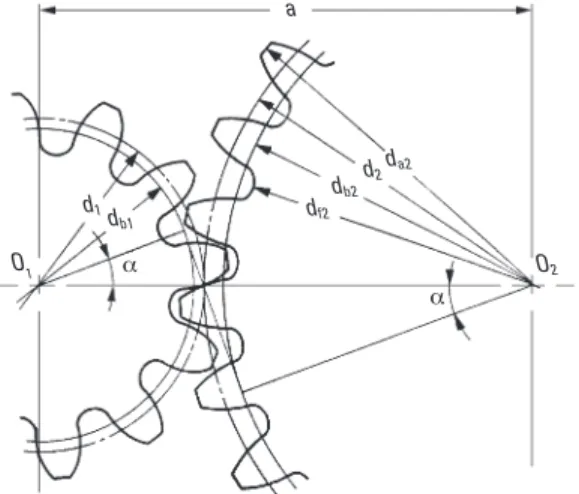
Figure 4-1shows the meshing of standard spur gears. The meshing of standard spur
gears means pitch circles of two gears contact and roll with each other. The calculation formulas are in Table 4-1.
a
da2
O1
Fig. 4-1 The Meshing of Standard Spur Gears
(a= 20°, z1 = 12, z2 = 24, x1 = x2 = 0) d2 db2 df2 d1d b1 a a O2 1 Module Pressure Angle Number of Teeth Center Distance Pitch Diameter Base Diameter Addendum Dedendum Outside Diameter Root Diameter m a z1, z2 * a 3 20° 12 24 54.000 36.000 72.000 33.829 67.658 3.000 3.750 42.000 78.000 28.500 64.500 zm d cos a 1.00m 1.25m d + 2m d – 2.5m
No. Item Symbol Formula Example
Pinion Gear Table 4-1 The Calculation of Standard Spur Gears
*The subscripts 1 and 2 of z1 and z2 denote pinion and gear. 2 4 5 6 7 8 9 10 (z1+ z2 )m * –––––––– 2 d db ha hf da df
All calculated values in Table 4-1 are based upon given module (m) and number of teeth (z1 and z2 ). If instead module (m), center distance (a) and speed ratio (i ) are given, then the number of teeth, z1 and z2, would be calculated with the formulas as shown in Table 4-2. 3
Metric
R
1
2
3
4
5
6
7
8
9
10
11
12
13
T
14
15
PHONE: 516.328.3300 • FAX: 516.326.8827 • WWW.SDP-SI.COMTable 4-2 The Calculation of Teeth Number
No. Item Symbol Formula Example
1 2 3 4 5 Module Center Distance Speed Ratio Sum of No. of Teeth Number of Teeth m a i z1+ z2 z1 , z2 3 54.000 0.8 36 16 20 2a –––– m i (z1+ z2 ) (z1+ z2 ) –––––– ––––– i + 1 i + 1
Note that the numbers of teeth probably will not be integer values by calculation with the formulas in Table 4-2. Then it is incumbent upon the designer to choose a set of integer numbers of teeth that are as close as possible to the theoretical values. This will likely result in both slightly changed gear ratio and center distance. Should the center distance be inviolable, it will then be necessary to resort to profile shifting. This will be discussed later in this section.
4.2 The Generating Of A Spur Gear
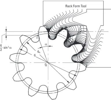
Involute gears can be readily generated by rack type cutters. The hob is in effect a rack cutter. Gear generation is also accomplished with gear type cutters using a shaper or planer machine.
Figure 4-2 illustrates how an involute gear tooth profile is generated. It shows how the pitch line of a rack cutter rolling on a pitch circle generates a spur gear.
Rack Form Tool
a O db d d –– sin 2a 2 I
Fig. 4-2 The Generating of a Standard Spur Gear
(a= 20°, z = 10, x = 0)
Metric
R
1
2
3
4
5
6
7
8
9
10
11
12
13
T
14
15
PHONE: 516.328.3300 • FAX: 516.326.8827 • WWW.SDP-SI.COM
T-36
4.3 Undercutting
From Figure 4-3, it can be seen that the maximum length of the line-of-contact is limited to the length of the common tangent. Any tooth addendum that extends beyond the tangent points (T and T') is not only useless, but interferes with the root fillet area of the mating tooth. This results in the typical undercut tooth, shown in Figure 4-4. The undercut not only weakens the tooth with a wasp-like waist, but also removes some of the useful involute adjacent to the base circle.
Fig. 4-3 Geometry of Contact Ratio
WZ = Length-of-Action B'Z = AB = Base Pitch( a Ra Rb a B AZ T' B' W T rb a ra
Fig. 4-4 Example of Undercut Standard Design Gear
(12 Teeth, 20° Pressure Angle)
From the geometry of the limiting length-of-contact (T-T', Figure 4-3), it is evident that interference is first encountered by the addenda of the gear teeth digging into the mating-pinion tooth flanks. Since addenda are standardized by a fixed value (ha = m), the interference condition becomes more severe as the number of teeth on the mating gear increases. The limit is reached when the gear becomes a rack. This is a realistic case since the hob is a rack-type cutter. The result is that standard gears with teeth numbers below a critical value are automatically undercut in the generating process. The condition for no undercutting in a standard spur gear is given by the expression:
mz
Max addendum = ha ≤ –––– sin 2 a
2
and the minimum number of teeth is: (4-1)
zc ≥ –––––– 2
sin 2 a
This indicates that the minimum number of teeth free of undercutting decreases with increasing pressure angle. For 14.5° the value of zc is 32, and for 20° it is 18. Thus, 20° pressure angle gears with low numbers of teeth have the advantage of much less undercutting and, therefore, are both stronger and smoother acting.
Metric
R
1
2
3
4
5
6
7
8
9
10
11
12
13
T
14
15
PHONE: 516.328.3300 • FAX: 516.326.8827 • WWW.SDP-SI.COM4.4 Enlarged Pinions
Undercutting of pinion teeth is undesirable because of losses of strength, contact ratio and smoothness of action. The severity of these faults depends upon how far below zc the teeth number is. Undercutting for the first few numbers is small and in many applications its adverse effects can be neglected.
For very small numbers of teeth, such as ten and smaller, and for high-precision applica-tions, undercutting should be avoided. This is achieved by pinion enlargement (or correction as often termed), where in the pinion teeth, still generated with a standard cutter, are shifted radially outward to form a full involute tooth free of undercut. The tooth is enlarged both radi-ally and circumfe ren tiradi-ally. Comparison of a tooth form before and after enlargement is shown in
Figure 4-5.
Fig. 4-5 Comparison of Enlarged and Undercut Standard Pinion
(13 Teeth, 20° Pressure Angle, Fine Pitch Standard)
Pitch Circle Base Circle
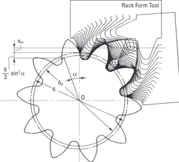
4.5 Profile Shifting
As Figure 4-2 shows, a gear with 20 degrees of pressure angle and 10 teeth will have a huge undercut volume. To prevent undercut, a positive correction must be introduced. A positive correction, as in Figure 4-6, can prevent undercut.
Fig. 4-6 Generating of Positive Shifted Spur Gear
Rack Form Tool
d –– sin 2 a 2 a O db d xm Metric
0
10
R
1
2
3
4
5
6
7
8
9
10
11
12
13
T
14
15
PHONE: 516.328.3300 • FAX: 516.326.8827 • WWW.SDP-SI.COM
T-38
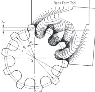
Undercutting will get worse if a negative correction is applied. See Figure 4-7.
The extra feed of gear cutter (xm) in Figures 4-6 and 4-7 is the amount of shift or correction. And x is the shift coefficient.
Fig. 4-7 The Generating of Negative Shifted Spur Gear
(a= 20°, z= 10, x= -0.5)
Rack Form Tool
O ddb
a
xm
The condition to prevent undercut in a spur gear is: zm
m – xm ≤ ––– sin 2 a (4-2) 2
The number of teeth without undercut will be: 2 (1 – x)
zc= –––––––– (4-3)
sin 2 a
The coefficient without undercut is: zc
x=1 – ––– sin 2 a (4-4)
2
Profile shift is not merely used to prevent undercut. It can be used to adjust center distance between two gears.
If a positive correction is applied, such as to prevent undercut in a pinion, the tooth thickness at top is thinner.
Table 4-3presents the calculation of top land thickness.
Metric
R
1
2
3
4
5
6
7
8
9
10
11
12
13
T
14
15
PHONE: 516.328.3300 • FAX: 516.326.8827 • WWW.SDP-SI.COMTable 4-3 The Calculations of Top Land Thickness
m = 2, a = 20°, z= 16, x = +0.3, d = 32, db = 30.07016 da = 37.2 aa = 36.06616° inv aa = 0.098835 inv a = 0.014904 q = 1.59815° (0.027893 radian) sa = 1.03762 aa q sa Pressure angle at outside circle of gear Half of top land angle of outside circle Top land thickness db cos–1
(
––)
da p 2xtan a –– + –––––– + (inva– invaa) 2z z qdaNo. Item Symbol Formula Example
1 2 3 (radian)
4.6 Profile Shifted Spur Gear
Figure 4-8shows the meshing of a pair of profile shifted gears. The key items in profile shifted gears are the operating (working) pitch diameters (dw)and the working (operating) pressure angle(aw). These values are obtainable from the operating (or i.e., actual) center distance and the following formulas:
z1 dw1 =2ax ––––– z1 + z2 z2 dw2=2ax ––––– (4-5) z1 + z2 db1+ db2 aw=cos–1
(
–––––––)
2ax ax dw1 d1db1 aw aw df2 db2 d2 dw2 da2 O2 O1Fig. 4-8 The Meshing of Profile Shifted Gears
(a = 20°, z1= 12, z2= 24, x1= +0.6, x2= +0.36)
Metric
R
1
2
3
4
5
6
7
8
9
10
11
12
13
T
14
15
PHONE: 516.328.3300 • FAX: 516.326.8827 • WWW.SDP-SI.COM
T-40
In the meshing of profile shifted gears, it is the operating pitch circles that are in contact and roll on each other that portrays gear action. The standard pitch circles no longer are of significance; and the operating pressure angle is what matters.
A standard spur gear is, according toTable 4-4, a profile shifted gear with 0 coefficient of shift; that is, x1 = x2 = 0.
h da df x1+ x2 2tan a
(
––––––)
+ inva z1+ z2 Find from Involute Function Tablez1+ z2 cos a –––––
(
––––– – 1)
2 cos aw z1+ z2(
–––– + y)
m 2 zm d cos a db ––––– cos aw (1 + y – x2)m (1 + y – x1)m [2.25 +y– (x1 + x2)]m d+ 2ha da – 2h m a z1 ,z2 x1 , x2 invaw aw y ax Module Pressure Angle Number of Teeth Coefficient of Profile Shift Involute Function aw Working Pressure Angle Center Distance Increment Factor Center DistanceItem Symbol Formula
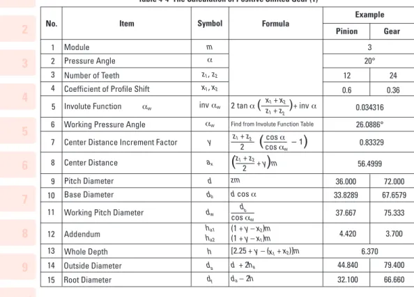
No. Example Pinion Gear 5 6 7 8 9 10 11 12 13 14 15 1 2 3 4 Pitch Diameter Base Diameter Whole Depth Outside Diameter Root Diameter ha1 ha2 d db dw 3 20° 12 24 0.6 0.36 0.034316 26.0886° 0.83329 56.4999 36.000 72.000 33.8289 67.6579 37.667 75.333 4.420 3.700 6.370 44.840 79.400 32.100 66.660
Table 4-4 The Calculation of Positive Shifted Gear (1)
Item Symbol Formula
No. Example ax y aw x1 +x2 x1 , x2 1 2 3 4 5 Center Distance
Center Distance Increment Factor Working Pressure Angle Sum of Coefficient of Profile Shift Coefficient of Profile Shift
ax z1+ z2 ––– – –––––– m 2 (z1+ z2)cos a cos–1
[
–––––––––––]
2y +z1+ z2 (z1+ z2) (inv aw – inv a) ––––––––––––––––– 2tan a 56.4999 0.8333 26.0886° 0.9600 0.6000 0.3600Table 4-5 The Calculation of Positive Shifted Gear (2) Table 4-5 is the inverse formula of items from 4 to 8 of Table 4-4. Working Pitch Diameter
Addendum
Metric
R
1
2
3
4
5
6
7
8
9
10
11
12
13
T
14
15
PHONE: 516.328.3300 • FAX: 516.326.8827 • WWW.SDP-SI.COM There are several theories concerning how to distribute the sum of coefficient of profile shift,(x1 + x2 ) into pinion, (x1 ) and gear, (x2 ) separately. BSS (British) and DIN (German) standards are the most often used. In the example above, the 12 tooth pinion was given sufficient correction to prevent undercut, and the residual profile shift was given to the mating gear.
4.7 Rack And Spur Gear
Table 4-6presents the method for calculating the mesh of a rack and spur gear.Figure 4-9ashows the pitch circle of a standard gear and the pitch line of the rack.
One rotation of the spur gear will displace the rack (l) one circumferential length of the gear's pitch circle, per the formula:
l= pmz (4-6)
Figure 4-9bshows a profile shifted spur gear, with positive correction xm, meshed with a rack. The spur gear has a larger pitch radius than standard, by the amount xm. Also, the pitch line of the rack has shifted outward by the amount xm.
Table 4-6presents the calculation of a meshed profile shifted spur gear and rack. If the correction factor x1 is 0, then it is the case of a standard gear meshed with the rack. The rack displacement, l, is not changed in any way by the profile shifting.Equation (4-6)
remains applicable for any amount of profile shift.
3 20°
Item Symbol Formula
No.
1 Module m
2 Pressure Angle a
3 Number of Teeth z
4 Coefficient of Profile Shift x
5 Height of Pitch Line H
6 Working Pressure Angle aw 7 Center Distance ax –––– zm +H+xm 2 zm 8 Pitch Diameter d 9 Base Diameter db 10 Working Pitch Diameter dw
11 Addendum ha 12 Whole Depth h 13 Outside Diameter da 14 Root Diameter df dcos a m (1 + x ) 2.25m d + 2ha da – 2h db ––––– cos aw Example Spur Gear Rack
–– 12 0.6 –– 32.000 20° 51.800 36.000 33.829 –– –– 36.000 4.800 3.000 6.750 45.600 32.100
Table 4-6 The Calculation of Dimensions of a Profile Shifted Spur Gear and a Rack
Metric