International Colloquium on Graph and Model
Transformation On the occasion of the 65th birthday of
Hartmut Ehrig
(GraMoT 2010)
Graph Modelling and Transformation: Theory meets Practice
Karsten Ehrig and Claudia Ermel
21 pages
Guest Editors: Claudia Ermel, Hartmut Ehrig, Fernando Orejas, Gabriele Taentzer Managing Editors: Tiziana Margaria, Julia Padberg, Gabriele Taentzer
Graph Modelling and Transformation: Theory meets Practice
Karsten Ehrig1and Claudia Ermel2
1BAM Bundesanstalt f¨ur Materialforschung und -pr¨ufung, Berlin, Germany
2Institut f¨ur Softwaretechnik und Theoretische Informatik
Technische Universit¨at Berlin, Germany [email protected]
Abstract: In this paper, we focus on the role of graphs and graph transformation for four practical application areas from software system development. We present the typical problems in these areas and investigate how the respective systems are modelled by graphs and graph transformation. In particular, we are interested in the usefulness of theoretical graph transformation results and graph transformation tools in order to solve these problems. Finally, we characterize concepts and tool features which are still missing in practice to solve the presented and related problems even better.
Keywords:graph modelling, graph transformation, graph transformation tools
1
Introduction
Graphs are one of the key concepts for modelling. Since the early days of mankind, graphs are used to depict the relationship between two or more entities as abstractions of real world systems and processes. The visual nature of graphs makes them an intuitive language for human beings to think and discuss about partitioning systems into different components, and about processes of running systems which can be drawn as related but changing system state graphs. Throughout the history of software engineering, graph models have been used for software system design, such as entity-relationship diagrams for databases, class diagrams for static software structure, and the diagram types offered by the Unified Modeling Language (UML) [OMG07] to model different static and dynamic system aspects. Yet, when it came to programming, often enough a yawning gap opened between what the modellers meant when designing their graph models and what the programmers encoded using standard textual programming languages, where the graph models played the role of a rough guideline for programmers. Ambitious programming projects resulted in failure, went over their budgets or proved to be unstable over time.
In all cases, the MDD perspective raises the importance of graph models and calls for rigorous methods to capture the semantics of graph models and their evolution over time [Eng00]. The fundamental notions behind graph models have been captured long ago by mathematical terms, thus allowing for rigorous reasoning at model level. Yet, experience shows that many problems in using formal methods in software development arise because the formal model and the prob-lem domain are too far apart. Since any software system is situated in a particular social context, this context (domain) should be represented also in models based on formal notations. Here, again, graph models with their visual nature are a good candidate for uniting the domain-specific and the formal aspects of real-world problems. Domain specific languages based on graphs may use a graphical concrete syntax with adequate intuitive symbols which are manipulated ade-quately to model dynamic system aspects. Thus, the system behaviour may be animated in a domain-specific visualization to validate system properties by domain experts.
Since real world systems evolve, their models need to model evolution as well. Algebraic graph transformation is a formally defined calculus based on graphs and graph transformation rules [EEPT06]. For ages, rules have proven to be extremely useful for describing computa-tions by local transformacomputa-tions. Areas like language definition, logic, functional programming, algebraic specification, term rewriting and expert systems have rules as key concepts. Graph transformation, also known as graph rewriting or graph reduction, combines the potential and advantages of both graphs and rules into a single computational paradigm.
In this paper, we summarize a few selected case studies from recent literature which have been modelled by graphs and algebraic graph transformation (reviewed inSection 2). In particular, we focus on four case studies from different application areas: a medical information system (Section 3), a model transformation between two different modelling notations (Section 4), a metabolic pathway analysis (Section 5), and a self-healing system (Section 6). For each applica-tion area, we ask the following quesapplica-tions:
1. What are typical problems in this area?
2. How can they be modelled by graphs or graph transformation?
3. What kind of graph transformation results can be applied to solve these problems?
4. What are missing graph modelling and transformation concepts and results?
In the evaluation (Section 7), we summarize the experiences gained from the case studies and state what kinds of concepts and results we find still missing.
2
Algebraic Graph Transformation: Background
For nearly 40 years, graph transformation has been studied in a variety of approaches, moti-vated by application domains such as pattern recognition, semantics of programming and visual modelling languages, specification of distributed systems etc. [EEKR99,EKMR99,BTMS99].
gluing of graphs. In fact, there are two main variants of the algebraic approach, the double and the single pushout approach. The double pushout (DPO) approach [EEPT06], is the formal basis for visual modelling of behavioural models and model transformations considered in this article. The DPO approach is based on category theory: a graph transformation rule is a pair of mor-phisms in the category of graphs with total graph mormor-phisms as arrows:r= (L←K→R)where K→Lis injective. GraphKis calledgluing graph. Another graph morphismm:L→Gmodels an occurrence ofLinGand is called amatch. Intuitively, this means thatLis a subgraph that is matched toG, and after a match is found, the rule can be applied.
Adirect transformationor application of rulerto graphGis de-fined by two pushout diagrams (see the diagram to the right). Ap-plying the rule,m(L)is replaced withm∗(R)in graphG, leading to the transformed graph H. Agraph transformation, or, more precisely, a graph transformation sequence, consists of zero or
L
(1) m
K
(2) l
o
o r //
R m∗
Goo D //H
more direct transformations, writtenG0 ∗
=⇒Gn. A set of graph rules is calledgraph
transfor-mation system. A type graphdefines a set of types which can be used to assign a type to the nodes and edges of a graph. The typing itself is done by a graph morphism from the graph to the type graph. Atyped graph transformation system GT S= (T G,P) consists of a type graphTG and a setPof typed graph rules. A(typed) graph grammar GG= (GT S,S)consists of a (typed) graph transformation systemGT Sand a (typed) start graphS. The(typed) graph language Lof GGis defined byL={G| ∃(typed) graph transformationS=⇒∗ G}.The key idea ofattributed graph transformation is to model graphs with node and edge attributes, i.e. an attributed graph is a pairAG= (G,A)of a graphGand a data type algebraA. Typed attributedgraph transforma-tion, combining process and data modelling proved to be well-suited to define and analyse visual models and model transformations [EEPT06,MVVK05].
A variety of tools for graph transformation exist [TEG+05] to be used as transformation engine and for analysis purposes, to reason about issues such as conflicts and dependencies of actions as well as consistency of object structures.
3
Case Study 1: Medical Information System
Problem
Information systems are very common nowadays in almost all common application areas of soft-ware systems. In health care, data from different domains like admission, physical examination, medical record archive, etc. have to be coordinated and presented to the employees. Data ma-nipulations, like the admission of a new patient, have to be supported intuitively.
Aim of the Model
Technique to solve the problem / realize the aim
We use typed, attributed graphs to model the abstract syntax of the information systems, and graph transformation rules on the abstract syntax model to define the operations to be performed by the clinical staff. Moreover, we combine the abstract syntax elements with concrete syntax symbols to visualize graphs in an adequate, domain-specific way. Constraints and application conditions are used to check the consistency of the model and the operations to be performed. From this model, the interface and operation code allowing the users to operate on the informa-tion system visually is generated automatically.
Overview of the model
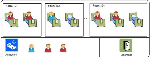
Figure 1shows icons for patients, beds, rooms, admission and discharge (from left to right) used in our information system.
Figure 1: Graphical Symbols for Medical Information System
InFigure 2, the current ward patient allocation diagram shows bed icons inside the room icons to represent the number of available beds in the ward rooms.
Figure 2: Sample User Interface Diagram for Medical Information System
A patient icon is connected with a bed if occupied, otherwise the bed is left empty. Patients currently not associated with a bed are shown next to the admission symbol. This requires a user action. Dragging anfemale patientsymbol onto afree bed symbol evokes ruleAdmission (Figure 3).
Figure 3: Sample RuleAdmission
Tool Support
TIGER 2 [BEEH09] is an generator of modeling tool environments for visual domain specific languages. In the modelling environment, a set of graph transformation rules called editing rules define the editing commands of the generated visual editor, i.e. the model syntax; on the other hand, a set of simulation rules may describe a model’s operational semantics.
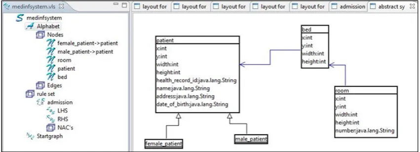
Figure 4: Abstract Syntax definition in TIGER2
Figure 4 shows the (simplified) abstract syntax of the case study modelled in TIGER 2. A patientis associated with abedlocated in aroomof the ward numbered with the attribute num-ber of data type String to allow for combinations of letters and numbers (e.g. ’room A15’). Nodepatientis an abstract node, specialized to nodesfemale patientandmale patient. The pa-tient attributehealth record id of is used for unique identification of the current health record in the system database. One patient may acquire more than one health record ids for different admissions. The attributesx,y,width, andheightare used for icon visualization.
Related Work
and edges. More sophisticated tools generating graph-based modelling environments that can be customized to various domains are e.g. Metaedit+ [TR03], the Generic Modeling Environment GME [AKL03] and DiaGen [Min07], a diagram editor generator based on graph transformation.
Unsolved Problems
Graph-based modelling environments need to integrate various domain specific editors and views for defining e.g. simulations and model transformations. All views have to be interconnected and customized to the domain. Up to now, suchmulti-view editorscannot be generated automatically from domain models by generators like GMF. We are convinced that a combination of EMF-based modeling tools [EMF09] and graph transformation tools [Tae06] provide a solid basis to define complex operations for editing, simulation, and model transformation of domain specific languages based on a well-defined theoretical background [BET08]. Up to now, a comprehensive generation framework combining graph transformation, EMF-based meta-modeling and for the generation of customized visual modelling environments has not yet been implemented.
4
Case Study 2: Business Process Model Transformation
Problem
The Business Process Modelling Notation (BPMN) [Whi04] is a graph-oriented language in which control and action nodes can be connected almost arbitrarily. It defines a Business Pro-cess Diagram (BPD), which is a kind of flowchart incorporating constructs tailored to business process modelling, such as AND-split, AND-join, XOR-split, XOR-join. It is supported by var-ious modelling tools but so far no systems can directly execute BPMN models. The Business Process Execution Language for Web Services (BPEL) [IBM03], on the other hand, is a mainly block-structured language. BPEL is emerging as a de-facto standard for implementing busi-ness processes on top of web services technology. Numerous platforms support the execution of BPEL processes.
Aim of the Model
The aim of this case study is to define the BPMN2BPEL model transformation at an adequate abstraction level. A challenge in formalizing the particular model transformation is the transla-tion of BPMNAndandXorconstructs to the corresponding BPEL language elementsFlowand Switch. Translating those constructs with ordinary graph transformation rules requires a complex control structure for guidance. We aim for an intuitive, visual description of the model transfor-mation where arbitrary many branches ofAndandXorconstructs can be treated in parallel.
Technique to solve the problem / realize the aim
We use typed, attributed graph transformation based on an integrated type graphT GI. This type
graph consists of the type graphs for the source and target language, and, additionally, reference nodes with arcs mapping source elements to target elements. We express model transformations directly byT GI-typed graph transformation rulesL←K→RwhereLbasically represents source
transformation starts with graphGStyped overT GS.
As T GS is a subgraph of T GI, GS is also typed
overT GI. During the model transformation process,
the intermediate graphsGS=G1, ..,Gnare all typed
overT GI. To delete all items inGnwhich are not
T GS
incS //
T GI ? _T GT incT
o
o
GS typeGS
O
O
r1 +3... rn +3
Gn typeGn
O
O
GT typeGT
O
O
o
o
typed over T GT, we can construct a restriction (a pullback in the category Graphs), which
deletes all those items in one step. In addition to normal graph transformation rules, we also use rule schemes to express parallel transformation of arbitrary many similar model element patterns. The application of rule schemes is defined by the concept of amalgamated graph trans-formation [BFH87].
Overview of the Model Transformation
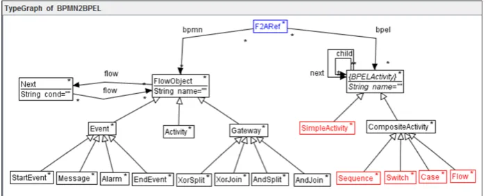
The complete model transformation case study is described in [BEE+10]. The type graph inte-grating the BPMN source model (left-hand part), the reference part connecting source and target model (the node typeF2ARefand its adjacent edge typesbpmnandbpel), and the BPEL target model (right-hand part) is shown inFigure 5.
Figure 5: BPMN2BPEL type graph
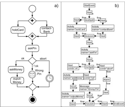
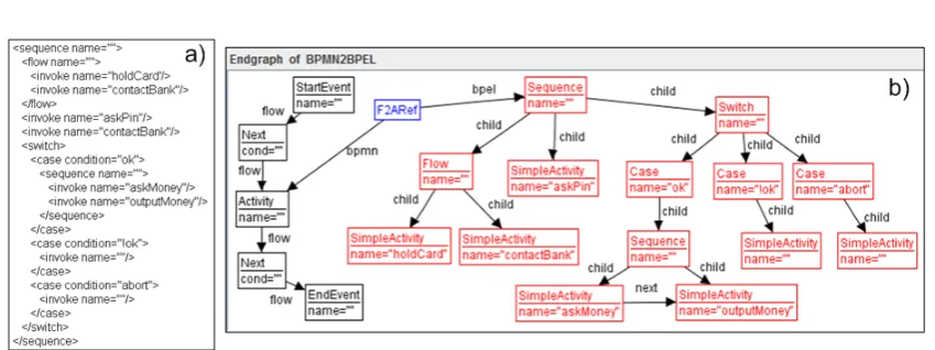
As an example we consider a BPMN diagram which models a person’s interaction with an ATM (see Figure 6 where the concrete and abstract syntax of the diagram are depicted). In the upper part, the ATM machine accepts and holds the card of the person while simultaneously contacting the bank for the account information. (The language elementsAndSplitandAndJoinare used to model parallel actions.) Afterwards, the display prompts the user for the PIN. Depending on the user’s input there are three alternative actions possible: (1) the user enters the correct PIN and can withdraw money, (2) a wrong PIN is entered – a message is displayed, (3) the operation is aborted – an alarm signal is given.
Figure 6: ATM machine in BPMN in concrete syntax (a) and abstract syntax (b)
of rules would not be sufficient to express this situation. Therefore, we here useamalgamated
graph transformation, a technique to specifyforall-operations on recurring model patterns (e.g.
for each branch in anAndconstruct). A multi-rule scheme contains a fixedkernel rule part and the recurring model pattern (calledmulti-rule). The kernel rule part defines the elements in the graph which are common to all recurring model patterns (e.g. theXorSplitandXorJoinnodes that surround all branches). Anamalgamated rule, induced by such a scheme, is a kind of parallel rule operating on all recurring model patterns in parallel but synchronized by the kernel rule part. Applying the amalgamated rule to a graph, it modifies all recurring matches of the model pattern, which overlap in the match of the kernel rule in one step.
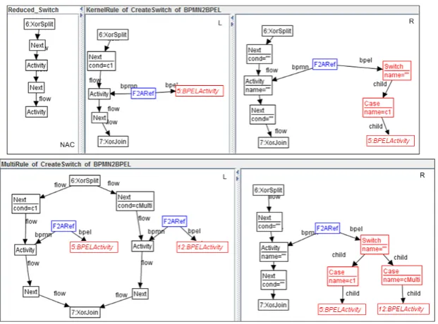
We model a multi-rule scheme as a rule embedding of the kernel rule part into the multi-rule, which contains in addition to the kernel rule part the recurring model pattern. The upper part ofFigure 7shows the kernel rule part, where one branch surrounded by anXorSplitandXorJoin is translated to a BPELSwitchnode with oneCasebranch where the condition in theNextnode is translated to a Case distinction. The multi-rule for processing And constructs is shown in the bottom part ofFigure 7. It extends the kernel rule by one more branch, which comprises the recurring model pattern, and translates it accordingly. The rule embedding from the kernel rule to the multi rule is indicated inFigure 7by corresponding numbers of some of the graph objects. For applying a multi-rule scheme, first, a match of the kernel rule is selected. Then, copies of the multi-rule are constructed, one for each new match of a multi-rule in the current host graph that overlaps with the match of the kernel rule. At last, all multi rule copies are glued at their corresponding kernel rule objects which leads to a new rule, theamalgamated rule. The application of the amalgamated rule is calledamalgamated graph transformation.
Figure 7: Multi-rule schemeCreateSwitch
(since we have three branches inFigure 6between theXorSplitand theXorJoin). The amalgamated rule inFigure 8is then used to translate the three branches in one step by applying it to the ATM graph inFigure 6.
Figure 8: Amalgamated rule of schemeCreateSwitchconstructed for the ATM model inFigure 6
Figure 9: ATM machine after transformation: (a) in concrete BPEL syntax, (b) in abstract syntax
Tool Support
We implemented the case study in our tool AGG [AGG09,BEL+10], supporting the definition of type graphs, typed attributed graph rules and constraints. AGG has been extended recently by support for defining and applying amalgamated graph transformation. All screenshots in this sec-tion are taken from the AGG editors for rules and interacsec-tion schemes. Moreover, AGG supports verification of model transformations w.r.t. termination and confluence (functional behaviour).
Related Work
A related model transformation approach based on graph transformation are triple graph gram-mars (TGGs) [Sch94] which transform pairs of related models simultaneously while maintaining their consistency. TGGs generate languages oftriple graphs, consisting of a source graphGSand a target graphGT, together with a correspondence graphGC“between” them. A triple graph is typed by a meta-model triple which contains the source and target meta-models, and declares the types of mappings between the elements of both languages. Atriple rule trconsists of triple graphsL= (SL←CL→T L)andR= (SR←CR→T R), and an injective triple graph morphism tr= (s,c,t):L→R, representing a non-deleting rule which adds target elements. Further graph transformation tools tuned for domain-specific model transformations are VIATRA2 [BNS+05] and the Graph Rewriting and Transformation Language (GReAT) [SAL+03]. A tool that also supports amalgamated graph transformation is AToM3[LVA04] where the technique is used for model simulation [LETE04].
Unsolved Problems
5
Case Study 3: Metabolic Pathway Analysis
Problem
Metabolic pathway analysis is one of the tools in biology and medicine in order to understand chemical reaction cycles in living cells. The problem is that often, reactions are analysed at the level of structural formulae only, thus summarising the number of atoms of certain types in a compound without keeping track of their identity.
Aim of the Model
This case study [EHL06] aims at understanding chemical reactions at the level of individual atoms or component molecules. In particular, we are interested in the analysis of causal depen-dencies between biochemical reactions. Given a metabolic pathway (a sequence of reactions) we would like to be able to trace the history of particular atoms or molecules. This is relevant, for example, when trying to anticipate the outcome of experiments using radioactive isotopes of such atoms. Such questions have been crucial to the detailed understanding of the nature of reactions like the citric acid cycle.
Techniques used to solve the problem / realize the aim
Biological systems and chemical reactions are characterized by their inherent concurrency, al-lowing reactions to take place simultaneously as long as they involve different resources and to keep track of causal dependencies and conflicts between them. Graph transformation systems provide concurrency concepts which are suitable to be applied in this area. For modeling the metabolic pathway, we propose a new hypergraph model for chemical compounds which refines the classical representation in terms of structural formulae in two different ways.
• Our representation keeps track of the identity of atoms or molecular components by means of the identities of hyperedges. In contrast, when writing down chemical reactions with structural formulae, the identities of the reacting atoms are not explicitly represented in the notation. In situations where several atoms of the same element are involved, this lack of information leads to ambiguity as to where a new atom is placed in the resulting molecule. Our graph transformation-based model allows to track atom identities by graph homomor-phisms between the graphs representing the compounds before and after the reaction.
• Modelling atoms as hyperedges, each connected to an ordered sequence of nodes, the rela-tive spatial orientation of different molecular components is recorded through the ordering of the nodes connected to a hyperedge.
Using this model we are able to trace the dependencies between different steps in the reaction based on individual atoms and their spatial arrangement.
preserve labels and assignments of nodes, that is,l2◦φE=l1andφV∗◦s1=s2◦φE. A morphism
thus has to respect the atom represented by an edge and also its chemical valence (number of bonds). Labelled hypergraphs can be considered as hierarchical graph structures. As shown by L¨owe [L¨ow93], pushouts can be computed elementwise for all hierarchical graph structures and therefore the standard graph transformation approaches can be applied.
Overview of the Model
We consider as an example the citric acid cycle, a classical, but non-trivial reaction for energy utilisation in living cells [ZPV95]. Our approach supports a molecular analysis of the cycle, trac-ing the flow of individual carbon atoms based on a simulation. This cycle is a series of chemical reactions of central importance in all living cells that utilise oxygen as part of cellular respiration. Starting withacetyl-CoA, one of the resulting products of the chemical conversion of carbohy-drates, fats and proteins, the citric acid cycle produces fast usable energy in the form ofNADH, GTP, andFADH2which are precursors of the well knownadenosine-tri-phosphate (ATP). The diagram to the right shows reaction 2 of the citric
acid cycle. The input agent of reaction 2,citrate, has two CH2COO− groups, one on the top and one on the bottom. To fit into the enzyme aconi-tase catalysing reaction 2, only the CH2COO− group marked with 3 is able to fit into the enzyme due to 3-dimensional spatial relations.
COO COO CH2 Isocitrate CH COO C H 1 1 2 2 3 3 4 4 COO COO CH2 Citrate CH2 COO C HO 1 1 2 2 3 3 4 4 HO
In our hypergraph model, we interpret the hyperedges as atoms and the nodes as bonds between them. The string s(e) of vertices incident to an edge e∈E gives the specific or-der of the bonds to other atoms, coding also their spatial configuration, as we will see. As ranked set of labels, we useA1={H, CH3,OH, . . .},A2={O, CH2,S, . . .},A3={CH, N, . . .},
A4={C, S, . . .}, . . .to denote elements of the periodic system or entire chemical groups. The rank of a label models the valence of an atom. For instance, a carbon atom withl(e) =C always hass(e) =v1v2v3v4, a word of length 4. Hence, we define C as a label of rank 4. For elements with more than one possible valence (e.g. sulphur), the corresponding label can belong to several of the setsAn. Given an organic molecule, we
represent the 3-dimensional configuration of the ligands of a C atom as a hypergraph by relating it to D-glyceraldehyde, one of the simplest chiral organic compounds. We impose a numbering on the ligands of a carbon atom such that a substitu-tion of ligand 1 by OH, ligand 2 by CHO, ligand 3 by CH2OH, and ligand 4 by H would result in
As example,Figure 10shows the representation of the prochiral moleculecitrateas a hyper-graph, where
V ={v1,v2, . . . ,v6},E={e1,e2, . . . ,e7},
s(e1) =v1,s(e2) =v1v2,s(e3) =v3,s(e4) =v2v3v4v5,s(e5) =v4,s(e6) =v5v6,s(e7) =v6 l(e1) =COO−,l(e2) =CH2,l(e3) =OH,l(e4) =C,l(e5) =COO−,l(e6) =CH2,l(e7) =COO−
Figure 10: Structural formula (left) and hypergraph representation (right) of citrate.
Tool Support
We provide an encoding of the model in terms of attributed bipartite graphs that can be imple-mented in the AGG system for simulation and analysis [Tae04,AGG09].
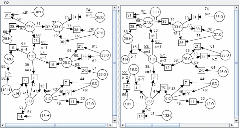
Figure 11shows reaction 2 of the citric acid cycle modelled in AGG. The enzymeaconitase accepts only the source agentcitratewith the indicatedoedge attribute order of the1:Catom in the left-hand side ofFigure 11. In this reaction the OH group of the1:Catom is exchanged with the OH group of the3:Catom. This leads to the new agentisocitrate.
Related Work
The use of graph transformation for biological systems has a long history (see [RV05]), but early applications were mostly devoted to the field of morphogenesis. Our approach focuses on biochemistry, a field which gained much importance in the last decades because of the growth of biotechnology. Providing automated assistance for analyzing biochemical reactions can help in understanding the principles which govern the processes in living cells.
Unsolved Problems
The citric acid cycle is a very common cycle for energy utilization in living cells. However, biological systems are very complex and hard to understand, so most of the biological path-ways are still not completely understood. For analyzing more complex pathpath-ways, big computer clusters are needed. Modelling with graph transformations might produce an overhead of data structures for the internal representation and computation with graphs. In general, the graph transformation problem is NP-complete. Putting several reactions together, the system might be unsolvable in a usable time frame. Recently, more focus has been given to the comparison of graph transformation tools with respect to performance (memory usage and efficiency). Starting with Varr´o’s benchmark study [VSV05], a transformation tool contest1 is held regularly nowa-days where scalability and performance of graph-based transformation tools are important issues (see also [RV10]).
6
Case Study 4: Self-Healing Automated Traffic-Light
Problem
Self-healing (SH-)systems are characterized by an automatic discovery of system failures, and techniques how to recover from these situations. The problem is that failures can occur at any time during system operation. It is very important for such systems that recovery actions can always be applied after a failure has occurred and that they always lead to a system that works as expected.
Aim of the Model
The aim of our model is to verify that SH-systems have certain self-healing properties. For an SH-system, we distinguish reachable, failure andnormal states (depending on which sets of constraints they fulfill), where reachable states split into normal and failure states. In particular, we call an SH-system is self-healing if each system state considered as failure state can be repaired, i.e. the system state after the repair action is considered asnormalstate. Furthermore, we want to ensure certain liveness properties of SH-systems. We call an SH-system deadlock-free if no reachable system state is a deadlock. A stronger liveness property isstrong cyclicity, meaning that each pair of reachable states can be reached from each other.
Technique to solve the problem / realize the aim
In this case study, we model SH-systems by typed attributed graph transformation systems
riched with graph constraints expressing their operational properties. We make use of theoretical results, i.e. sufficient static conditions for self-healing properties, deadlock-freeness and liveness of SH-systems.
Overview of the Model
The complete case study is given in [EER+10]. We model an automated Traffic Light System (TLS). The traffic light technology is based upon electromagnetic sensors buried some centime-ters underneath the asphalt of car lanes. The sensors register traffic data and send them to other system components. The TLS is connected to cameras which record videos of the violations and automatically send them to the center of operations. In addition to the normal behavior, we may have failures caused by a loss of signals between a traffic light or a camera and the supervisor component. For each of the failures there are corresponding repair actions which can be applied after monitoring the failures during run-time.
We define the Traffic Light SH-systemTLSby a type graphT G, an initial state, a set of normal rulesRnorm(modelling the ideal behaviour), a set of failure rulesRf ail modelling failures, a set
of repair rulesRrepair, which are the inverse repair rules, and sets of constraints that characterize
properties of states being either consistent or failure states.
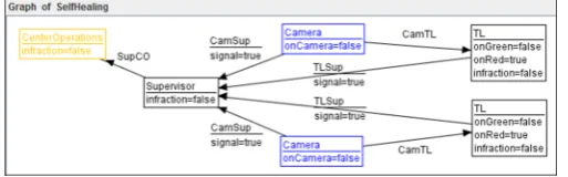
In our example, we model a single traffic crossing with two traffic lights in directions north-south and east-west. In the initial state (see Figure 12), both traffic lights are red and there are no cars at the crossing. TheTL nodes represent the traffic lights, connected to a crossing supervisor component, and to cameras which are currently not in use (onCamera=false). The
infractionattribute becomes true in the case that a car runs a red light.
Figure 12: TLS initial stateGinit
Normal rulesRnormmodel the behaviour of cars arriving at the crossing and leaving it, as well
as cars running a red light and being filmed by a camera. Failure rulesRenv (applied from the
environment) model the loss of a signal of either a traffic light (in this case thesignalattribute of
aTLSupedge changes tofalse), or of a camera (here, thesignalattribute of a CamSupbecomes
false). Repair rulesRr pr model the recovery from the respective signal loss. In [EER+10], we
formalize operational properties, including self-healing and deadlock-freeness and provide static conditions for them based on rule set analysis.
An SH-System SHS is calledself-healing, if each failure state can be repaired, i.e.∀Ginit⇒∗G
via (Rnorm∪Renv) with G∈Fail(SHS) ∃ G⇒+ G0 via Rr pr with G0 ∈Norm(SHS). SHS is
calleddeadlock-free, if no reachable state is a deadlock, i.e. ∀G0∈Reach(SHS) ∃G0
p
=⇒G1 via p∈Rnorm∪Renv∪Rr pr. In particular, SHS isnormally deadlock-free, if no state reachable
via normal rules is a (normal) deadlock, i.e.∀Ginit⇒∗G0viaRnorm∃G0
p
SHS is strongly cyclic, if each pair of reachable states can be reached from each other, i.e. ∀G0,G1∈Reach(SHS)∃G0⇒∗G1viaRnorm∪Renv∪Rr pr.
For the analysis of SH-systems, we have the following results concerning self-healing proper-ties and deadlock-freeness: An SH-System is self-healing, if it has the following three properproper-ties: 1) the initial state is normal and all normal rules preserve normal states, 2) each pair(p,q)∈Renv ×Rnormis sequentially independent, and 3) the effect of each environment rule can be repaired
up to normal transformations. Furthermore, an SH-System is deadlock-free, if it is normally deadlock-free, and each pair(p,q)∈(Renv∪Rr pr)×Rnormis sequentially and parallel
indepen-dent. For the proof of these analysis results and further self-healing and liveness properties see [EER+10].
Tool Support
For the automatic analysis of the static conditions ensuring the self-healing properties we use AGG, in particular to check on sequential and parallel independence of pairs of rules. AGG computes dependencies and conflicts of rules and visualizes their reasons. All properties are verified for our traffic light system.
Related Work
Different related approaches exist, either based on graph transformation [6,14,15,16,17,18,19] or on temporal logics and model checking [20,21,22]. In many cases, though, the state space of behavioral system models becomes too large or even infinite, and in this case model checking techniques have their limitations.
Unsolved Problems
A helpful extension of the formal approach would be the analysis and verification of consistency properties using the theory of graph constraints and nested application conditions in [EHL10b]. Moreover, we will investigate how far the techniques for SH-systems can be used and extended for more general self-adaptive systems.
7
Evaluation and Conclusion
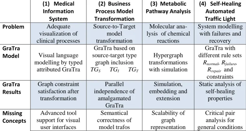
The table inFigure 13summarizes the problem domains and modelling features and results for our four case studies. In the last line, we state concepts which, from our point of view, are missing not only for the particular case study presented in this paper but rather in general for the respective application domain.
(1) Medical Information
System
(2) Business Process Model Transformation
(3) Metabolic Pathway Analysis
(4) Self-Healing Automated Traffic Light
Problem Adequate
visualization of clinical processes Source-to-Target model transformation Molecular ana-lysis of chemical
reactions
System modelling with failures and
recovery GraTra
Model Visual language
modelling by typed attributed GraTra
GraTra based on source-target type
graph inclusion
TGS → TGI ← TGT
Hypergraph transformations with simulation
GraTra with
different rule sets
Rnormal, Rfailure,
Rrepair and constraints GraTra Results Graph constraint satisfaction after transformation Parallel independence of amalgamated GraTra Simulation, embedding and extension
Static analysis of self-healing
properties
Missing Concepts
Advanced tool support for visual
user interfaces Semantical correctness of model trafos Scalability of graph representation Critical pair analysis for general conditions
Figure 13: Comparison of Case Studies
Model transformations from domain-specific models to more machine-centric formats like
Case Study (2)have become a necessary step towards unified and standards-based development environments. Here, important results have been achieved in recent years concerning the syntac-tical correctness of model transformations and their functional behaviour, i.e. termination and uniqueness. Also, for triple graph grammars, properties concerning the consistency of source and target models w.r.t. triple rules can be shown formally. An open problem for model transfor-mations remains the semantical correctness, i.e. how can be shown in general that the behaviour of the source and the target model are equivalent (see also [Erm09]).
Often, a validation by simulation is helpful to provide new insights on behavioural system properties. Case Study (3) showed that a simulation by graph transformation, supported by tools, can help to find a suitable abstraction level and visualize model features (like molecule identities) which are not easily seen using standard techniques and tools. Here, the problem arises that in contrast to standard tools, a graph representation might lead to a larger memory consumption than e.g. the standard format for chemical formulae. Morover, scalability, i.e. effieciency of the rewriting in large models is a general problem. These problems have been tackled already by comparing and improving the performance of existing graph transformation engines and by experimenting with different data formats for graphs and rules and by optimizing the pattern matching process which is the bottleneck of graph transformation. Here, more future work will be necessary for further optimizations.
pair analysis of rules with nested application conditions while a formal background is presented already in [EHL+10a]. .
Some of the “missing concepts” are topics of ongoing research projects2. We are confident that the visibility of graph transformation technology in practice will be further enhanced and that meetings between theory and practice, aided by good tool support, will be the rule rather than the exception.
Bibliography
[AGG09] TFS-Group, TU Berlin. AGG. 2009.http://tfs.cs.tu-berlin.de/agg.
[AKL03] A. Agrawal, G. Karsai, A. Ledeczi. An End-to-End Domain-Driven Software De-velopment Framework. InProc. Conf. on Object-Oriented Programming, Systems, Languages and Applications. ACM SIGPLAN, USA, 2003.
[BEE+10] E. Biermann, H. Ehrig, C. Ermel, U. Golas, G. Taentzer. Parallel Independence of Amalgamated Graph Transformations Applied to Model Transformation. InGraph Transformations and Model-Driven Engineering. Essays Dedicated to Manfred Nagl. LNCS 5765. Springer, 2010. To appear.
http://tfs.cs.tu-berlin.de/publikationen/Papers10/BEE+10.pdf
[BEEH09] E. Biermann, K. Ehrig, C. Ermel, J. Hurrelmann. Generation of Simulation Views for Domain Specific Modeling Languages based on the Eclipse Modeling Frame-work. In Taentzer and Heimdahl (eds.),Automated Software Engineering (ASE’09). Pp. 625 – 629. IEEE Press, 2009.
[BEL+10] E. Biermann, C. Ermel, L. Lambers, U. Prange, G. Taentzer. Introduction to AGG and EMF Tiger by Modeling a Conference Scheduling System.Int. Journal on Soft-ware Tools for Technology Transfer12(3-4):245–261, Juli 2010.
doi:10.1007/s10009-010-0154-x
http://www.springerlink.com/content/p4n1g45627852743/
[BET08] E. Biermann, C. Ermel, G. Taentzer. Precise Semantics of EMF Model Transfor-mations by Graph Transformation. In Czarnecki (ed.), Proc. Int. Conf. on Model Driven Engineering Languages and Systems (MoDELS’08). LNCS 5301, pp. 53– 67. Springer, 2008.http://tfs.cs.tu-berlin.de/publikationen/Papers08/BET08.pdf
[B´ez05] J. B´ezivin. On the unification power of models. Software and System Modeling 4(2):171–188, 2005.
[BFH87] P. B¨ohm, H.-R. Fonio, A. Habel. Amalgamation of graph transformations: a syn-chronization mechanism.Computer and System Sciences (JCSS)34:377–408, 1987.
2See e.g. our projectBehaviour Simulation and Equivalence of Systems Modelled by Graph Transformation
[BNS+05] A. Balogh, A. N´emeth, A. Schmidt, I. Rath, D. V´ag´o, D. Varr´o, A. Pataricza. The VIATRA2 Model Transformation Framework. In Proc. European Conference on Model Driven Architecture (ECMDA’05). 2005.
[BTMS99] R. Bardohl, G. Taentzer, M. Minas, A. Sch¨urr. Application of Graph Transforma-tion to Visual Languages. In Ehrig et al. (eds.), Handbook of Graph Grammars and Computing by Graph Transformation, Volume 2: Applications, Languages and Tools. World Scientific, 1999.
[EEKR99] H. Ehrig, G. Engels, H.-J. Kreowski, G. Rozenberg (eds.). Handbook of Graph Grammars and Computing by Graph Transformation, Volume 2: Applications, Lan-guages and Tools. World Scientific, 1999.
[EEPT06] H. Ehrig, K. Ehrig, U. Prange, G. Taentzer. Fundamentals of Algebraic Graph Transformation. EATCS Monographs in Theor. Comp. Science. Springer, 2006.
[EER+10] H. Ehrig, C. Ermel, O. Runge, A. Bucchiarone, P. Pelliccione. Formal Analysis and Verification of Self-Healing Systems. InProc. Int. Conf. on Fundamental Aspects of Software Engineering (FASE’10). LNCS 6013, pp. 139–153. Springer, 2010. http://www.springerlink.com/content/hv51032524v38321/
[EHL06] K. Ehrig, R. Heckel, G. Lajios. Molecular Analysis of Metabolic Pathway with Graph Transformation. In Proc. Int. Conf. on Graph Transformation (ICGT’06). LNCS 4178, pp. 107–121. Springer, 2006.
[EHL+10a] H. Ehrig, A. Habel, L. Lambers, F. Orejas, U. Golas. Local Confluence for Rules with Nested Application Conditions. InProc. Int. Conf. on Graph Transformation (ICGT’10). 2010. To appear.
http://tfs.cs.tu-berlin.de/publikationen/Papers10/EHL+10.pdf
[EHL10b] H. Ehrig, A. Habel, L. Lambers. Parallelism and Concurrency Theorems for Rules with Nested Application Conditions.Electr. Comm. of the EASST26, 2010. http://journal.ub.tu-berlin.de/index.php/eceasst/issue/view/36
[EKMR99] H. Ehrig, H.-J. Kreowski, U. Montanari, G. Rozenberg (eds.).Handbook of Graph Grammars and Computing by Graph Transformation. Vol 3: Concurrency, Paral-lelism and Distribution. World Scientific, 1999.
[EMF09] Eclipse Consortium. Eclipse Modeling Framework Technology. 2009. http://www.eclipse.org/modeling/emft.
[Eng00] G. Engels. Graph Changes are Everywhere: The Role of Graph Transformations in Software Engineering. InProc. Joint APPLIGRAPH and GETGRATS Workshop on Graph Transformation Systems. pp. 12-13. TU Berlin, 2000.
[GEH10] U. Golas, H. Ehrig, A. Habel. Multi-Amalgamation in Adhesive Categories. In Proc. Int. Conf. on Graph Transformation (ICGT’10). 2010. To appear.
http://tfs.cs.tu-berlin.de/publikationen/Papers10/GEH10.pdf
[GMF07] Eclipse Consortium. Eclipse Graphical Modeling Framework (GMF). 2007. http://www.eclipse.org/gmf.
[HP09] A. Habel, K.-H. Pennemann. Correctness of high-level transformation systems rela-tive to nested conditions.Mathematical Structures in Comp. Science19:1–52, 2009.
[IBM03] IBM, BEA Systems, Microsoft, SAP AG, Siebel Systems. Business Process Exe-cution Language for Web Services version 1.1. May 2003.
http://www.ibm.com/developerworks/library/ws-bpel/.
[LETE04] J. de Lara, C. Ermel, G. Taentzer, K. Ehrig. Parallel Graph Transformation for Model Simulation applied to Timed Transition Petri Nets.ENTCS109:17–29, 2004. http://tfs.cs.tu-berlin.de/publikationen/Papers04/LETE04.pdf
[L¨ow93] M. L¨owe. Algebraic Approach to Single-Pushout Graph Transformation. TCS 109:181–224, 1993.
[LVA04] J. de Lara, H. Vangheluwe, M. Alfonseca. Meta-Modelling and Graph Grammars for Multi-Paradigm Modelling in AToM3.Software and System Modeling: Special Section on Graph Transformations and Visual Modeling Techniques3(3):194–209, 2004.
[Min07] M. Minas. DiaGen / DiaMeta – The Diagram Editor Generator. 2007. http://www.unibw.de/inf2/DiaGen/.
[Mos96] G. Moss (ed.).IUPAC Basic Terminology of Stereochemistry. Volume 68(12). Pure & Applied Chemistry, 1996.
[MVVK05] T. Mens, P. Van Gorp, D. Varr`o, G. Karsai. Applying a Model Transformation Tax-onomy to Graph Transformation Technology . InProc. Int. Workshop on Graph and Model Transformation (GraMoT’05). ENTCS 152, pp. 143–159. Elsevier Science, 2005.
[OMG07] Object Management Group. Unified Modeling Language: Superstructure – Version 2.1.1. 2007.http://www.omg.org/technology/documents/formal/uml.htm.
[Ope09] OpenEmbeDD: Model Driven Engineering open-source platform for Real-Time & Embedded systems. 2009.http://openembedd.org.
[Roz97] G. Rozenberg.Handbook of Graph Grammars and Computing by Graph Transfor-mations, Volume 1: Foundations. World Scientific, 1997.
[RV10] A. Rensink, P. Van Gorp (eds.).International Journal on Software Tools for Tech-nology Transfer (STTT), Special Section on Graph Transformation Tool Contest 2008. Volume 12(3-4). Springer, 2010.
http://www.springerlink.com/content/p4n1g45627852743/
[SAL+03] J. Sprinkle, A. Agrawal, T. Levendovszky, F. Shi, G. Karsai. Domain model transla-tion using graph transformatransla-tions. InInt. Conf. on Engineering of Computer-Based Systems. Pp. 159–168. 2003.
[Sch94] A. Sch¨urr. Specification of Graph Translators with Triple Graph Grammars. In WG94 20th Int. Workshop on Graph-Theoretic Concepts in Computer Science. LNCS 903, pp. 151–163. Springer, 1994.
[Tae04] G. Taentzer. AGG: A Graph Transformation Environment for Modeling and Vali-dation of Software. InApplication of Graph Transformations with Industrial Rele-vance (AGTIVE’03). LNCS 3062, pp. 446 – 456. Springer, 2004.
[Tae06] G. Taentzer. Characterizing Tools for Visual Modeling Techniques. In Ehrig et al. (eds.),Lecture Notes of SegraVis Advanced School on Visual Modelling Techniques. Univ. of Leicester, 2006.
http://tfs.cs.tu-berlin.de/publikationen/Papers06/Tae06a.pdf
[TEG+05] G. Taentzer, K. Ehrig, E. Guerra, J. de Lara, L. Lengyel, T. Levendovsky, U. Prange, D. Varro, S. Varro-Gyapay. Model Transformation by Graph Transformation: A Comparative Study. InProc. Workshop Model Transformation in Practice. 2005. http://tfs.cs.tu-berlin.de/publikationen/Papers05/TEG+05.pdf
[TR03] J. Tolvanen, M. Rossi. MetaEdit+: Defining and Using Domain-Specific Modeling Languages and Code Generators. InProc. Conf. on Object-oriented programming, systems, languages, and applications (OOPSLA ’03). Pp. 92–93. ACM Press, 2003.
[VSV05] G. Varr´o, A. Sch¨urr, D. Varr´o. Benchmarking for Graph Transformation. InProc. IEEE Symposium on Visual Languages and Human-Centric Computing (VL/HCC 05). Pp. 79–88. IEEE Press, 2005.
[Whi04] S. White. Business Process Modeling Notation (BPMN) Version 1.0. BPMI.org, 2004.