Visually-Guided Manipulation Techniques for Robotic
Autonomous Underwater Panel Interventions
A. Pe˜nalver, J. P´erez, J. J. Fern´andez, J. Sales, P. J. Sanz, J. C. Garc´ıa, D. Fornas, R. Mar´ın
Computer Science and Engineering Department, Universitat Jaume I, Castell´on, Spain.
e-mail: {penalvea, japerez, fernandj, salesj, sanzp, garciaju, dfornas, rmarin}@uji.es
Abstract
The long term of this ongoing research has to do with increasing the au-tonomy levels for underwater intervention missions. Bearing in mind that the specific mission to face has been the intervention on a panel, in this paper some results in different development stages are presented by using the real mechatronics and the panel mockup. Furthermore, some details are highlighted describing two methodologies implemented for the required visually-guided manipulation algorithms, and also a roadmap explaining the different testbeds used for experimental validation, in increasing complex-ity order, are presented. It is worth mentioning that the aforementioned results would be impossible without previous generated know-how for both, the complete developed mechatronics for the autonomous underwater vehicle for intervention, and the required 3D simulation tool. In summary, thanks to the implemented approach, the intervention system is able to control the way in which the gripper approximates and manipulates the two panel devices (i.e. a valve and a connector) in autonomous manner and, results in differ-ent scenarios demonstrate the reliability and feasibility of this autonomous intervention system in water tank and pool conditions.
Keywords: Underwater Intervention, Autonomous Manipulation, I-AUV, Robot Kinematics, 3D Simulation, Vision Guidance, Panel Intervention
1. Introduction
Due to the high number of applications related with the underwater in-dustry and, unfortunately, maritime disasters (e.g. shipwrecks or leaks on offshore platform), the number of underwater robot interventions has in-creased considerably during the last two decades. We can sum up the most common underwater applications in the following list:
• Oil and gas industry: inspection and repairing of submerged infrastruc-tures.
• Search and Recovery: localization and grasping objects on the seafloor.
• Deep water Archaeology: to document submerged sites, using high resolution 2D/3D seafloor mapping techniques.
• Science: periodic maintenance of underwater permanent observatories. The mostly used technology in these examples is a Remote Operated Vehicle (ROV) that are launched from support vessels, and remotely oper-ated by expert pilots through an umbilical communication cable and complex control interfaces. Looking for higher autonomy levels in underwater inter-vention missions, a new underwater robot concept is being developed. This robot, called I-AUV (Intervention Autonomous Underwater Vehicle), lacks the umbilical communications cable and has attached a robotic arm to per-form intervention tasks.
Presently, endowing an I-AUV with the ability to manipulate an underwa-ter panel in a permanent observatory is one of the challenges of the TRITON marine robotics research project, which is focused on the development of au-tonomous intervention technologies really close to the real needs of the final user and, as such, it can facilitate the potential technological transfer of its results. This project, entitled “Multisensory Based Underwater Intervention through Cooperative Marine Robots” and founded by the Spanish Science and Innovation Ministry, is coordinated at the Universitat Jaume I (UJI) and includes three sub-projects: COMAROB (“Cooperative Robotics”, under re-sponsibility of the Universitat de Girona, UdG), GRASPER (“Autonomous Manipulation”, under responsibility of the Universitat Jaume I, UJI) and VISUAL2 (“Multisensorial Perception”, under responsibility of the Universi-tat de les Illes Balears, UIB). The project proposes two scenarios as a proof of concept to demonstrate the developed capabilities: (1) the search and
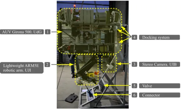
Figure 1: TRITON hardware system with its components attached to an underwater panel mockup.
1 AUV Girona 500. UdG
3 Stereo Camera. UIB 2
Lightweight ARM5E robotic arm. UJI
4 Docking system
6 Connector 5 Valve
recovery of an object of interest (e.g. a “black-box mockup” of a crashed airplane), and (2) the intervention on an underwater panel in a permanent observatory. Related to the main goals to achieve in the GRASPER sub-project and focused on the second scenario, this paper presents the recent progress towards autonomous underwater manipulation and a new algorithm for visually-guiding the manipulation actions. In order to evaluate the new algorithm, a mockup of an underwater panel in a permanent observatory intervention has been used (see Fig. 1).
In the next sections, the methodology followed to perform interventions with the manipulator arm mounted on the AUV is presented. First of all, in section 2, an extensive review of related works and state of the art is pro-vided. In Section 3, a visually-guided algorithm to control the robotic arm is explained and developed. The aim of this algorithm is to increase the ro-bustness of the robotic arm, by preventing calibration joint errors. Section 4 describes the methodology to manipulate a valve and a connector (hot-stab). Section 5 describes a roadmap for experimental validation developed from the experience of previous projects (RAUVI, TRIDENT) and describes
suc-cessful results of turn a valve and unplug/plug a connector in a water tank and pool conditions. Finally, Section 6 provides some conclusions, work in progress and future improvements to the system.
2. State of the Art
Planning a grasp in a regular environment is a well-known problem, be-cause of the large number of possibilities of hand configurations, grasp types and object properties. Although the most common approach has been the model-based paradigm (using physical laws to model the object shape, con-tacts and forces), some researchers has been focused on grasp analysis (the study of the physical properties of a given grasp) and grasps synthesis (the computation of grasps that meet certain desirable properties) [1]. Unfortu-nately, these two last approaches can be applied to complex and uncertain environments, due to because they rely on assumptions that are difficult to satisfy.
The current trend is to incorporate sensor information for grasp planning and synthesis, such as vision [2, 3, 4, 5, 6] or range sensors [7]. In this line, several approaches have also adopted machine learning techniques to deter-mine the relevant features that indicate a successful grasp [8, 4, 9, 10]. Others make use human demonstrations for learning grasp tasks [11]. Most of these approaches commonly consider grasps as a fixed number of contact locations with no regard to hand geometry [1, 12]. Some recent work includes kine-matics constraints of the hand in order to prune the search space [13, 14, 15]. Alternatively, the so-called knowledge-based approach tries to simplify the grasp planning problem by reasoning on a more symbolic level. Objects are often described using shape primitives [16, 17], grasp prototypes are defined in terms of purposeful hand preshapes [13, 15], and the planning and selection of grasps is made according to programmed decision rules [18]. Recently, the knowledge-based approach has been combined with vision-force-tactile feed-back and task-related features that improve the robot performance in real scenarios [19].
Regarding autonomous manipulation in underwater environments, after the pioneering works in the 90s (OTTER [20], ODIN [21]), significant ad-vances in this direction arrived during the last decade, especially when the first simple autonomous operations at sea were demonstrated. Most of the advances were obtained in multi-partner research projects like the ones listed hereafter:
• UNION 1996-99 [22]: The project focused mainly on the development of coordinated control and sensing strategies for combined manipulator and vehicle systems. UNION represents the first mechatronic assembly of a complete vehicle-manipulator system for automated manipulation.
• AMADEUS 1993-99 [23]: Amadeus had two phases: develop a dexter-ous gripper suitable for underwater applications and coordinated con-trol of two underwater electro-mechanical arms. The project demon-strated the coordinated motion of the two fixed based manipulators while manipulating a rigid object inside a water tank.
• SWIMMER 1999-01 [24]: It was a hybrid AUV/ROV intervention sys-tem, where an AUV shuttle transports an intervention ROV to the subsea. SWIMMER was able to autonomously transit to the seafloor and dock to a subsea cradle based docking station. Once the vehicle was docked, the transported ROV was deployed and the intervention was carried out in a conventional teleoperated way.
• ALIVE 2001-04 [25]: The ALIVE vehicle was equipped with two hy-draulic grippers for docking in a subsea intervention panel using an imaging sonar and a manipulator arm. It has been reported as the first AUV able to autonomously carry out a manipulation action consisting in opening/closing a valve in a subsea panel.
• SAUVIM 1997-09 [26]: SAUVIM focused on the free floating manipula-tion concept and demonstrated accurate navigamanipula-tion and stamanipula-tion keeping being the first project to demonstrate autonomous recovery of an a pri-ori known object. The object was endowed with artificial landmarks and the robot autonomously located it and hooked it with a recovery device while hovering.
• TRIDENT 2010-12 [27]: TRIDENT project proposes a new method-ology to provide multipurpose dexterous manipulation capabilities for intervention operations in unknown, unstructured and underwater en-vironments. In the TRIDENT project, a multipurpose generic inter-vention is composed of two phases. In the first phase, the I-AUV is deployed for surveying a given region of interest on the seabed and build an image photo-mosaic. The target of interest is then identified on the mosaic and the manipulation action is specified by means of
a suitable user interface. After that, during the second phase, the I-AUV navigates close to the identified target, localizes it and executes the intervention mission, doing all of that in an autonomous manner.
• PANDORA 2011-15 [28]: The aim of the PANDORA project is to extend the range of tasks that can be carried on autonomously and increase their complexity while reducing the need for operator assis-tances. Dynamic adaptation to the change of conditions is very im-portant while addressing autonomy in the real world and not just in well-known situation. The key of PANDORA is the ability to recognize failure and respond to it, at all levels of abstraction.
In summary, to the best of authors’ knowledge, grasping and manipula-tion remain open research problems, and this situamanipula-tion becomes drastically worst in underwater scenarios, due to the new difficulties arose under the very hostile underwater conditions. Only few commercial robots, mainly specialized for very specific and limited operations, and mostly used in the offshore industry, has been endowed with grasping and manipulation capa-bilities. Related with research projects, only some projects like SWIMMER, ALIVE, SAUVIM, RAUVI [29], TRIDENT, TRITON and PANDORA have demonstrated reasonable performance in sea trials.
For further bibliography related to the motion control of I-AUVs and its manipulation systems, refer to [30], that addresses the main control aspects in underwater manipulation tasks; and [31], which provides an extensive tract on sensory-based autonomous manipulation for intervention tasks in unstructured environments.
3. Visually-guided algorithm to control a robotic arm
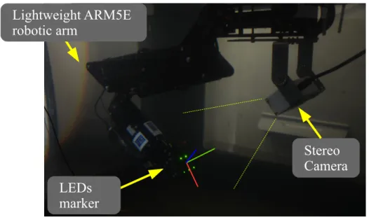
In many robotic arms, some errors such as bad initializations or miscal-ibration of the joints that affect to the kinematics of the arm, can appear. A new algorithm to correct this errors has been developed. This algorithm is able to control, in an autonomous way, the position and orientation of the end-effector of the Light-Weight ARM5E robotic arm [32] with respect to its base (see Fig. 2).
Then, the algorithm, updates the values of each joint of the robotic arm from the calculation of the position of the arm end-effector by the detection of a marker placed in a known position of the arm. Two different markers has been used, an AR(Augmented Reality) marker, and a pattern made with five
Figure 2: Underwater platform equipped with the Light-Weight ARM5E robotic arm. An algorithm estimates the position and orientation of the end-effector using a camera fixed on the platform and a marker placed on the arm gripper.
Stereo
Camera
Lightweight ARM5E
robotic arm
LEDs
marker
light LEDs (Light Emitting Diodes) (see Fig. 3). Each marker is placed in a side of the arm gripper. With this configuration the vehicle can dynamically switch the detection method when the light conditions change.
Furthermore, using the algorithm, the process of obtaining the extrinsics parameters of the camera with respect to the base of the arm is performed autonomously.
LED patterns have been previously used by the authors in the context of localization of mobile robots in low-visibility conditions [33, 34]. The use of high intensity LEDs improve the detection of the markers using optical sensors like cameras, where visibility is not optimal, like in smoke-filled en-vironments or underwater in presence of water turbidity.
3.1. Detection of the marker
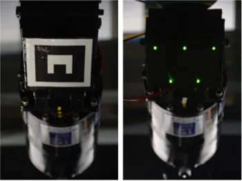
The two different kinds of markers, commented previously, are being at-tached to the robotic arm and, one or the other would be used depending of the light conditions during the intervention. With good visibility and light conditions, the AR marker provides better results but in case this marker cannot be detected properly, the LED pattern can be used.
Figure 3: Arm end-effector with two different visual markers placed at each side of the gripper: AR marker (left), and a pattern made with five LEDs (right).
3.1.1. AR marker detection
The AR marker is a white figure with a known size drawn over a black square (see Fig. 3). This marker is detected using the ARToolkit library [35]. Despite ARToolKit is a software library for building AR applications, the library provides multiple methods for detecting and localizing the position and orientation of a marker.
3.1.2. Pattern LEDs detection
A new algorithm to detect a pattern made of LEDs from an image and calculate its position and orientation (pose) with respect to the camera has been developed. The pattern consists in five LEDs, three of them aligned on the top of the marker and two, also aligned, on the bottom (see Fig. 3).
The algorithm can be divided in two parts, the first one consists in an-alyzing the image in order to detect in which image coordinates the LEDs are located. And the second one has the finality of obtaining the pose of the marker using as input the previously computed coordinates where the LEDs are seen.
3.1.2.1. LED detector. First of all, the received image is converted from RGB (Red, Green, Yellow) color space to Grayscale, and all the pixels with a gray value lower than a threshold are discarded.
Then, the resulting image is analyzed in one of two different ways de-pending on the last marker detection.
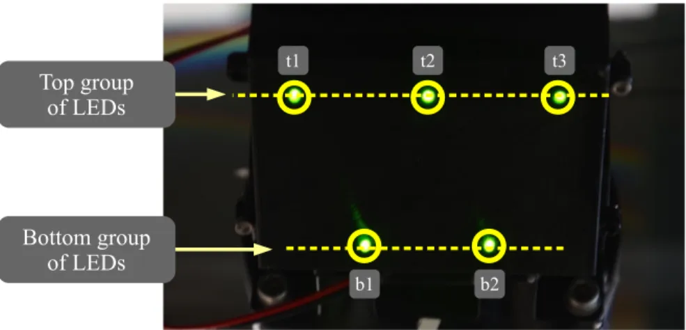
1. In case the algorithm is not initialized, either because it is the first it-eration of the algorithm or because a certain period of time has elapsed (the duration of this period will be explained below) from the last de-tection of the pose of the marker, the follow steps are performed. First of all, a connected components algorithm [36] is used to join and label the pixels that belong to the same LED in the whole image. If after that process there are more or less components than the number of LEDs (five in this case), the image is discarded. On the contrary, each component determines the light produced by one of the five LEDs. Then, the center of mass of each component is calculated to obtain with a subpixel accuracy the pixel that corresponds to the center of each LED. The next step consists in calculating which of the five LEDs of the pattern matches with each of the five selected pixels. The first searched pixels are the ones which are on the top of the pattern (see Fig. 4). They belong, more or less, to the same straight line. The distances between each of the selected pixels and the lines that cross the other selected pixels in pairs, are calculated. Then, by choosing the lowest distance, it is possible to assure that those three pixels (the one which is the point and the two which are crossed by the line), represent the three LEDs on the top of the pattern.
arg min
a,b,c
f(a, b, c) := {distance(a,−→bc)|∀a, b, c∈P ixels:a6=b6=c}
(1) In order to determine which of these three pixels is in the middle, the distances between a pixel and the other two is calculated and summed for each of them. So, the pixel with the lowest distance is in the middle and therefore it is labeled as t2.
The next step consists in labeling the two pixels that correspond to the LEDs of the bottom of the marker (b1 and b2). These two pixels
are those that were not used in the last step. Firstly, the pixel which is between these two pixels is calculated (bm). Then, one of the two pixels of the bottom (pb) is selected and the cross product between the vectors (−t−−2bm,→ 0) and (−−→t2pb,0) is calculated. If thez component of the resultant vector is negative, pb is the pixel illuminated by the LED b1 and if it is positive, by the LED b2 (see Fig. 5). Finally, in order to label the two remaining pixels, the pixel which is the closest tob1 ist1 and the furthest is b2.
Figure 4: Labeled pattern LEDs. t1 t2 t3 b1 b2 Top group of LEDs Bottom group of LEDs
2. If the algorithm has been initialized, instead of looking for the LEDs throughout the whole image, each pixel is searched around the last position where each LED was found. So, the time between the capture of the image that is being analyzed and the last image successfully processed, is calculated. The more time elapsed, the higher is the search radius around the last position where each LED was found. In the event that the elapsed time causes that two search areas match in any pixel, it will be considered that the algorithm has lost the initialization and needs to be reinitialized returning to the first stage. If the search areas do not match, the connected components algorithm is used in each one. If there is not any component or there is more than one, the image is discarded. In other case, the center of mass of each component is calculated and labeled as its predecessor.
Using these two stages, once the algorithm has been initialized, the time consumed by the process of detecting the LEDs is shorter and possible out-liers are avoided because the search area is smaller.
3.1.2.2. Pose estimation. After the LEDs detection stage, the 3D pose of the centroid marker must be calculated. For that, the ViSP library [37] has been used. This library provides a method which determines the relationship between 3D coordinates of points (or features like segments, lines, ellipses . . . ) and their 2D projections onto the image plane. In the case of our marker, the 3D coordinates of each LED respect to the centroid of the marker is given to
Figure 5: Scheme of how to determine which pixel corresponds tob1 andb2 usingt2 and the auxiliary pixelbm.
t2
b1 bm
t2
b2 bm
the method in order to initialize it. Then, each time the method receives the pixels calculated in the previous phase, it is able to calculate the 3D pose of the marker (see Fig. 6).
3.2. Transformation between the camera and the end effector
Once the marker has been detected, the previous algorithms provide its pose with respect to the camera (cMm, which is the homogeneous matrix that represents the relationship between two frames, in this cases the camera c and the marker m). Therefore, the next step consists in obtaining the transformation between the camera and the end-effector of the arm (cMe). For this, it just needed to multiply the homogeneous matrix between the camera and the marker (cMm) by the relationship between the marker and the end-effector (mMe), which must be known:
cMe = cMm ∗ mMe
For this experiment, the markers has been placed on the top of the gripper (one in each side) and the end-effector of this arm is in the tip of this gripper. Thus, the transformation between the markers and the end-effector, depends, in addition to the static measures (see Fig. 7), on the opening of the gripper at each moment.
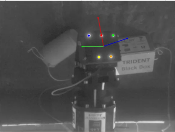
Figure 6: LED marker detected and analyzed, during an intervention, to obtain its pose.
The relationship between the markers and the end-effector for this grip-per, is detailed as follows:
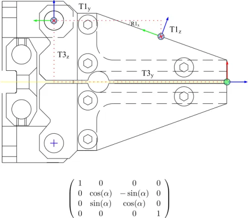
• The first transformation is a rotation around the x axis (R1x) in order to place the marker frame parallel to the palm of the gripper followed by a translation about the y (T1y) and z (T1z) axis in order to place the frame in the joint of the wrist of the gripper which allows the arm open and close the gripper (mMw):
1 0 0 0
0 cos(R1x) −sin(R1x) T1y cos(R1x)−T1z sin(R1x)
0 sin(R1x) cos(R1x) T1z cos(R1x) + T1y sin(R1x)
0 0 0 1
• The second transformation is a rotation around the x axis, which de-pends on the opening α of the hand in each detection of the marker:
Figure 7: Static transformations between the marker and the end-effector. T3y T3z T1y T1z R1x 1 0 0 0 0 cos(α) −sin(α) 0 0 sin(α) cos(α) 0 0 0 0 1
• The next transformation is a translation about the y (T3y) and z (T3z) axis in order to place the frame in the position of the end-effector (wMe): 1 0 0 0 0 1 0 T3y 0 0 1 T3z 0 0 0 1
• Finally, two rotations around the x (R4x) and z (R4z) axis are needed to orientate the frame like the end-effector frame:
cos(R4z) −sin(R4z) 0 0
cos(R4x) sin(R4z) cos(R4x) cos(R4z) −sin(R4x) 0
sin(R4x) sin(R4z) cos(R4z) sin(R4x) cos(R4x) 0
0 0 0 1
As a result, the transformation between the marker and the end effector (mMe) is: cos(R4z) −sin(R4z) 0 0 σ2 sin(R4z) cos(R4z) σ2 −σ1 σ3 sin(R4z) σ1 cos(R4z) σ1 σ2 σ4 0 0 0 1 where: σ1 = sin(α+ R1x+ R4x) σ2 = cos(α+ R1x+ R4x) σ3 = T3y cos(α+ R1x)−T3z sin(α+ R1x) + T1y cos(R1x)−T1z sin(R1x) σ4 = T3z cos(α+ R1x) + T3y sin(α+ R1x) + T1z cos(R1x) + T1y sin(R1x)
3.3. Transformation between the base of the arm and the camera
In order to obtain the relationship between the base of the arm and the camera (bMc), the arm is placed in a configuration that allows the cam-era to see the marker that is going to be used and therefore, calculate the transformation between it and the end-effector (cMe) at this moment. On the other hand, the relationship between the base of the arm and the end-effector (bMe) is calculated by means of the direct kinematics of the arm at this moment. Once these two matrices (cMe and bMe) have been obtained, in order to calculate the transformation between the base of the arm and the camera (bMc), just a product operation is needed:
bMc = bMe∗ (cMe)−1
This part of the algorithm must be done preferably in a moment when the user is sure that the arm is well calibrated, for example just after the initialization, because the matrix obtained will be used in the next steps and this matrix depends directly on the values of the joints.
3.4. Updating the joints
Once the process of initialization of the algorithm has been done, the camera will be used to continuously detects the marker. For each detection, the following steps are performed in order to obtain the real value of each joint and update them:
1. Calculate the relationship between the base of the arm and the end-effector (bMe) at this moment, using the detection of the marker (cMe) and the values calculated in the initialization of the algorithm (bMc):
bMe = bMc ∗cMe
2. Obtain the real value of the joints (q), using the inverse kinematic (IK) of the arm for the frame (bMe) calculated in the previous step:
q = IK(bMe)
3. Update the internal values of the arm with the values obtained in the previous step.
3.5. Kinematic control of the arm
Due to the fact that the algorithm updates the internal values of the joints, the user does not need to be careful about whether the marker is de-tected or not. If during a period of time the camera cannot detect the marker, the values of the joints are updated depending of its movement, whereupon some errors due to miscalibration can be added, but in the moment that the camera can detect the marker again, these errors are cancelled. Despite the possible errors during the no detection time, these errors will always be equal or smaller than the errors produced without the algorithm. This is because the errors are produced when the arm is moving, thus the movement executed by the arm from the last position without errors is always either equal or smaller.
4. The methodology for the intervention
In order to validate the second scenario of TRITON, a mission consisting in docking, manipulating and undocking an underwater panel autonomously, has been addressed. However, this paper is focused only on the manipulation part of the mission.
Thus, once the vehicle has successfully docked the underwater panel, the intervention begins. Two basic operations have been defined to solve in com-pletely autonomous manner: (1) open/close a valve and (2) plug/unplug a hot-stab connector. The main steps followed for the intervention are sum-marized hereinafter:
4.1. Initialization of the Visual Kinematic Controller
First of all, the Visual Kinematic Controller must be initialized. For this, the first preferable step is to initialize the robotic arm, to be sure that the values of the joints have not suffered any kind of miscalibration. Then, the arm has to be moved to a predefined initial configuration that allows the camera to see clearly the marker. At this moment, the arm waits until the camera estimates the position and orientation of the marker and the algorithm calculates the transformation between the base of the arm and the camera (bMc) following the steps detailed in previous sections. Henceforth, the Visual Kinematic Controller is updating the internal values of each joint for each detection of the marker.
4.2. Detection of the object to Manipulate
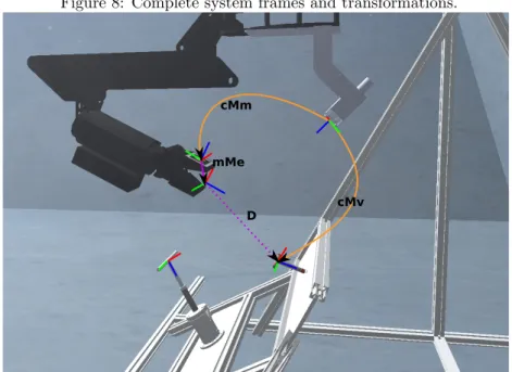
Once the Visual Kinematic Controller has been initialized, a service de-veloped by the UIB is started. This service, using the same camera that detects the marker, estimates the position and orientation of the object to manipulate with respect to the camera (cMo). In order to know the distance between the end-effector and the object to manipulate (eMo), the system uses the transformation from the base of the arm to the camera (bMc), and the inverse of the direct kinematics (DK) of the arm at this moment (eMb) (see Fig. 8):
eMb = DK−1()
bMc = (cMm ∗ mMe∗ eMb)−1 eMo = eMb ∗bMc ∗ cMo 4.3. Manipulation
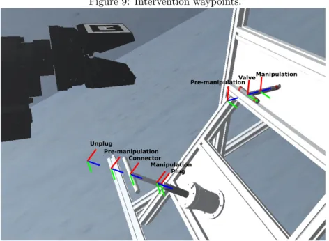
After the system has been completely initialized, the manipulation starts. In order to reach the positions to manipulate the objects in a correct way, some waypoints respect to the position of the object have been defined (see Fig. 9). In order to reach each waypoint, the system calculates the Cartesian distance between the end-effector and the waypoint, and using a Cartesian velocity control, the end-effector tries to reach the position of the waypoint. Due to the characteristics of the arm used, the Light-Weight ARM5E, that has just four rotation D.O.F, the reached orientation of the waypoint is not taken into account. Therefore, both the valve and the connector must be inside a quite wide range of positions reachable for this arm.
Figure 8: Complete system frames and transformations.
cMm
cMv D
mMe
4.3.1. Open/Close the Valve
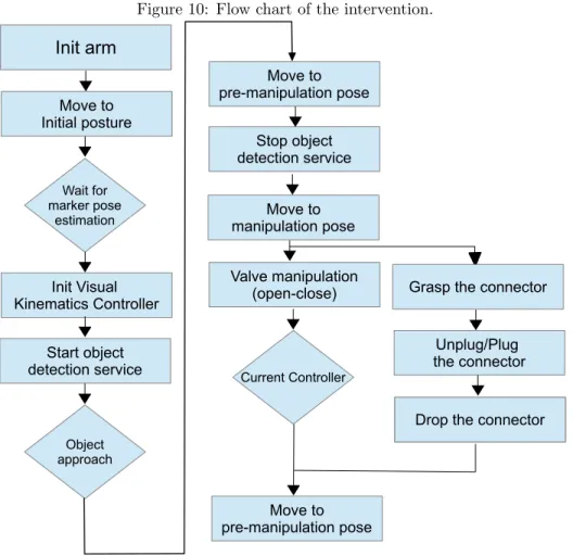
The valve manipulation is composed of open and close actions (see Fig. 10), which are here performed in the same manipulation process. However they can be performed independently. The next steps are followed to open and close the valve:
1. Start the service that provides the position and orientation of the valve. 2. Reach the pre-manipulation waypoint. This waypoint is a translation of seven centimeters in the -z axis with respect to the frame of the valve.
3. Open the gripper until the pre-established opening for manipulation. 4. Stop the valve pose service to avoid wrong detections when the arm
occludes the valve.
5. Reach the manipulation waypoint. This waypoint is a translation of three centimeters in the z axis respect to the frame of the valve. The translation is just three centimeters because is not necessary to keep the valve completely within the gripper to manipulate it.
6. Turn the gripper to the right to open the valve, until the current of the wrist joint exceeds a threshold.
Figure 9: Intervention waypoints. Pre-manipulation Manipulation Valve Connector Pre-manipulation Unplug Manipulation Plug
7. Turn the gripper to the left to close the valve, until the current of the wrist joint exceeds a threshold.
8. Open the gripper.
9. Reach the pre-manipulation waypoint.
4.3.2. Plug/Unplug the Hot-Stab Connector
The Hot-Stab manipulation is also composed of two operation which are performed successively (see Fig. 10). First, the connector is grasped and unplugged from the panel, then it is plugged to its socket and dropped. The next steps are followed to operate the connector:
1. Start the service that provides the position and orientation of the con-nector.
2. Reach the pre-manipulation waypoint. This waypoint is a translation of seven centimeters in the -z axis with respect to the frame of the connector.
3. Fully open the gripper.
4. Stop the service to avoid wrong detections when the arm occludes the connector.
Figure 10: Flow chart of the intervention. Init arm Move to Initial posture Start object detection service Wait for marker pose estimation Move to pre-manipulation pose Valve manipulation (open-close) Object approach Move to manipulation pose Init Visual Kinematics Controller Current Controller Move to pre-manipulation pose Stop object detection service
Grasp the connector
Unplug/Plug the connector
Drop the connector Drop the connector
5. Reach the manipulation waypoint. This waypoint is a translation of eight centimeters in the z axis with respect to the frame of the valve. In this case, it is necessary that the valve is completely within the gripper in order to align the T-groove of the gripper with the T-handle of the connector to make possible a robust grasping.
6. Close the gripper completely.
7. Reach the unplug waypoint. This waypoint is a translation of eleven centimeters in the –z axis with respect to the frame of the connector. In this waypoint, the connector fully out of the socket.
8. Reach the plug waypoint. This waypoint is a translation of nine cen-timeters in the z axis with respect to the frame of the connector. This waypoint is one centimeter deeper than the manipulation waypoint,
Figure 11: The four testbeds designed for the experimental roadmap are instantiated for a specific intervention mission (i.e. intervention on a panel).
Simulation
Real Scenario 1: Water tank
Increasing Complexity
Real Scenario 2: CIRS pool
Real Scenario 3: Harbour
because sometimes it is necessary to exert a bit of force to be sure that the connector has entered completely.
9. Fully open the gripper.
10. Reach the pre-manipulation waypoint.
5. The roadmap for experimental validation
Following the know-how generated through previous projects (RAUVI, TRIDENT), a roadmap has been developed for experimental validation, in-dependently of the underwater intervention context. In Fig. 11 the four basic steps designed for the roadmap are instantiated for a specific interven-tion mission (i.e. interveninterven-tion on a panel).
5.1. Simulation
The first step is validating the algorithms and the whole system in sim-ulation. Abstraction from hardware problems allows to think in different solutions. Different approaches were tested in simulation in order to achieve the desired results, such as in [38], where a 3D laser reconstruction was used
instead of stereo cameras. The only difference between simulation and real scenario is the physics. Although UWSim simulates physics, it is in exper-imental state so it just simulates collisions. In consequence, manipulation algorithms were slightly modified to work on simulation using position stop instead of current while manipulating the valve. The whole system was suc-cessfully tested under UWSim, as can be seen on Fig. 12.
5.2. Real scenario 1: water tank at Universitat Jaume I
After the task validation within the UWSim, the system is almost ready to perform the intervention in a real scenario. Thus, once the arm and the stereo camera systems, which will be used in the I-AUV, are integrated, the system was tested in a water tank with a panel mockup of an Underwater Ob-servatory (see Fig. 13). As it has been mention before, the camera attached to the arm is in charge of identifying the marker placed in the end-effector as well as the marker next to the connector.
One of the complete sequence can be watched on-line in (http://youtu.
be/6pYBL-6Tw4c and http://youtu.be/_WkQYtcLsMU). And the joint
evo-lution during the valve and connector manipulation and the different steps described in Fig. 10, are depicted in Figs. 14 and 15 respectively.
It is worth mentioning that the validation was tested combining different conditions:
• Attaching the arm to a fixed-base without perturbations: the arm was attached to a fixed-base, which allows the arm to perform the interven-tion in perfect condiinterven-tions.
• The panel is perfectly aligned to the arm: this is the perfect condition for grasping the hot-stab and handle the valve.
• Adding perturbations to the system: bearing in mind the shallow water intervention in Girona’s harbour, some perturbations were added to the system. We assume that in Girona’s harbour, the I-AUV will be perturbed due to water currents, so as well as the docking vehicle should be as much stable as possible, the grasping algorithms should be reliable in these conditions. The perturbations were introduced in the system manually, just by moving the arm base.
Figure 12: Intervention simulation in UWSim: valve and connector (hot-stab) manipula-tion.
Figure 13: Intervention in water tank conditions at UJI: valve and connector (hot-stab) manipulation.
Figure 14: Joint evolution during valve manipulation. 0 0.2 0.4 0.6 0.8 1 1.2 1.4 1.6 1.8 2 0 5 10 15 20 25 30 35
Joint values (radians)
Time (seconds) Slew Shoulder Elbow JawRotate JawOpening S1 S1 S2 S2 S3 S4 S4 S3 Open hand
Reach manipulation pose Open valve
Close valve
Figure 15: Joint evolution during connector manipulation.
-0.2 0 0.2 0.4 0.6 0.8 1 1.2 0 10 20 30 40 50 60 70
Joint values (radians)
Time (seconds)
Joint evolution during connector manipulation Slew Shoulder Elbow JawRotate JawOpening Reach
5.3. Real scenario 2: swimming pool at Universitat de Girona
Once the experimental validation in the water tank concluded and seeing the good results obtained, the system was tested in more difficult conditions. The experiments were carried out at the swimming pool facilities at the CIRS (Underwater Vision and Robotics Research Center, UdG), which has a depth of 5 meters and simulates the difficulties that could appear in a real scenario better than the water tank. An additional difficulty of these experiments was the integration of the vehicle with the arm and the stereo cameras. In the same manner as in the water tank, the stereo camera is in charge of detecting the marker placed in the gripper of the arm and the marker situated next to the connector.
It is worth mentioning that the position and orientation of the vehicle with respect to the panel after a docking can suffer little changes. Therefore, in order to demonstrate that the system is robust and able to manipulate the panel independently of the position and orientation of the arm, once the connector has been unplugged, the vehicle undocks and docks the panel and then the arm plugs the connector.
The intervention was successfully demonstrate by performing the com-plete sequence several times (see Fig. 16).
One of the complete sequence can be watched on-line in (https://youtu.
be/6bDzYVvhrxo). The joint evolution during the valve and connector
ma-nipulation and the different steps described in the Fig. 10, are depicted in Figs. 14 and 15 respectively. Further details about the experiments in the swimming pool can be found in [39].
5.4. Real scenario 3: shallow water
In a later date, the same experiments carried out in the CIRS swimming pool, were performed in shallow water conditions at the Sant Feliu de Guixols harbour (Girona, Spain). The conditions for this field experiments were realistic with a depth of twelve meters and a varying low visibility. The operations were performed successfully (see Fig. 16) and the results are currently being analyzed for future publication.
6. Conclusion and Future Lines
This paper presents, concerning the GRASPER project focus in under-water manipulation, the results obtained in different conditions. The aim of the GRASPER, which is sub-project of the TRITON project, is to increase
Figure 16: Intervention in the swimming pool at CIRS: valve and connector (hot-stab) manipulation. For each image both an external and onboard views are shown.
!! !
!
!! !
!
Figure 17: Joint evolution during valve manipulation. -0.5 0 0.5 1 1.5 2 0 10 20 30 40 50 60 70 80 90 100
Joint Values (radians)
Time (seconds) Slew Shoulder Elbow JawRotate JawOpening S1 S2 S3 S4 S5 S6 S7 S1 S2 S4 S3
Reach premanipulation pose
Open hand
Reach manipulation pose
Open valve S5 S6 S7 Close valve Open hand
Reach premanipulation pose
Figure 18: Joint evolution during connector manipulation.
0 0.5 1 1.5 2 0 50 100 150 200 250 300
Joint Values (radians)
Time (seconds)
Reach premanipulation pose
S1 S2 S3 S4 S5 S6
Open hand and Reach
manipulation pose
Close hand Unplug connector Undock and dock Plug connector S1 S2 S3 S4 S5 S6 S7 S7Drop connector Slew Shoulder Elbow JawRotate JawOpening
Figure 19: Plugging the connector at the Sant Feliu de Guixol harbour.
the autonomy levels of an underwater intervention system. In particular, this paper describes two methodologies implemented for the visually-guided manipulation algorithms. Furthermore, a roadmap explaining the different testbeds used for experimental validation, in increasing complexity order, has been presented. These testbeds includes, for a suitable validation, a simula-tor (UWSim) and a real system (hand-arm and vision) tested in water tank conditions at UJI. Then, after a successful result, the integrated system (I-AUV) was tested in a swimming pool (CIRS, UdG). Finally, the system was successfully tested during sea trials, although the results obtained are still being analyzed. Summarizing, an autonomous intervention has been demon-strated in different environments, under the Spanish coordinated TRITON project, including the docking (out of the scope of this paper) and the inter-vention on a panel, with two basic operations: ‘open and close’ a valve, and ‘plug and unplug’ a connector. As future lines, it is worth mentioning that cooperation research actions are now open to explore other paradigms for im-provements in manipulation like those based on “learning by demonstration” [40].
Acknowledgements
This work was partly supported by Spanish Ministry of Research and Innovation DPI2011-27977-C03 (TRITON Project) and DPI2014-57746-C3
(MERBOTS Project), by Foundation Caixa Castell´o-Bancaixa and Univer-sitat Jaume I grant PID2010-12, by UniverUniver-sitat Jaume I PhD grants PRE-DOC/2012/47 and PREDOC/2013/46, and by Generalitat Valenciana PhD grant ACIF/2014/298. We would like also to acknowledge the support of our partners inside the Spanish Coordinated Projects TRITON and MERBOTS: Universitat de les Illes Balears, UIB (subprojects VISUAL2 and SUPERION) and Universitat de Girona, UdG (subprojects COMAROB and ARCHROV). [1] K. Shimoga, Robot grasp synthesis: A survey, International Journal of
Robotics Research 3(15) (1996) 230. 266.
[2] A. Morales, G. Recatal´a, P. Sanz, A. del Pobil, Heuristic vision-based computation of planar antipodal grasps on unknown objects, in: IEEE International Conference on Robotics and Automation (ICRA), Vol. 1, 2001, pp. 583–588. doi:10.1109/ROBOT.2001.932613.
[3] M. S. A. Hauck, J. R¨uttinger, G. F¨arber, Visual determination of 3d grasping points on unknown objects with a binocular camera system, In IEEE International Conference on Robotics and Automation (1999) 272.278.
[4] J. P. J. Coelho, R. Grupen., Developing haptic and visual perceptual categories for reaching and grasping with a humanoid robot, Robotics and Autonomus Systems 37 (2001) 195.218.
[5] R. Cipolla, N. Hollinghurst., Visually guided grasping in unstructured environments., Robotics and Autonomous Systems 37 (1997) 195–218. [6] P. Sanz, A. Requena, J. Inesta, A. Del Pobil, Grasping the
not-so-obvious: vision-based object handling for industrial applica-tions, Robotics Automation Magazine, IEEE 12 (3) (2005) 44–52. doi:10.1109/MRA.2005.1511868.
[7] R. D. G. B. R.B. Rusu, A. Holzbach, M. Beetz., Perception for mobile manipulation and grasping using active stereo, Humanoids.
[8] A. F. A. Morales, E. Chinellato, A. del Pobil, Experimental prediction of the performance of grasps tasks from visual features, International Journal of Humanoid Robotics (2004) 671.691.
[9] T. F. I. Kamon, S. Edelman, Learning visually guided grasping: A test case in sensorimotor learning, IEEE Transactions on Systems, Man and Cybernetics part A, 28 (3) (1998) 266 – 276.
[10] P. J. Sanz, R. Mar´ın, J. S. S´anchez, Including efficient object recog-nition capabilities in online robots: from a statistical to a neural-network classifier, Systems, Man, and Cybernetics, Part C: Appli-cations and Reviews, IEEE Transactions on 35 (1) (2005) 87–96. doi:10.1109/TSMCC.2004.840055.
[11] S. Ekvall, D. Kragic, Interactive grasp learning based on human demon-stration, In IEEE Internacional Conference on Robotics and Automation (ICRA).
[12] A. Bicchi, V. Kumar, Robotic grasping and contact: a review, in: Robotics and Automation, 2000. Proceedings. ICRA ’00. IEEE International Conference on, Vol. 1, 2000, pp. 348–353 vol.1. doi:10.1109/ROBOT.2000.844081.
[13] A. T. Miller, S. Knoop, H. I. Christensen, P. K. Allen, Automatic grasp planning using shape primitives., in: IEEE International Conference on Robotics and Automation, Taipei, Taiwan, 2003, pp. 1824–1829.
[14] C. Borst, M. Fischer, G. Hirzinger, Grasping the dice by dicing the grasp, in: IEEE/RSJ International Conference on Intelligent Robots and Systems, Las Vegas, Nevada, USA, 2003.
[15] A. Morales, T. Asfour, P. Azad, S. Knoop, R. Dillmann, Integrated grasp planning and visual object localization for a humanoid robot with five-fingered hands, in: IEEE/RSJ International Conference on Intelligent Robots and Systems, Beijing, China, 2006, pp. 5663–5668.
[16] T. I. H. Liu, G. Bekey., The multi-dimensional quality of task require-ments for dextrous robot hand control, In IEEE International Confer-ence on Robotics and Automation (1989) 452.457.
[17] S. Stansfield, Robotic grasping of unknown objects: A knowledge-based approach, The International Journal of Robotics Research 10 (4) (1991) 314–326. doi:10.1177/027836499101000402.
[18] G. Bekey, H. Liu, R. Tomovic, W. Karplus, Knowledge-based control of grasping in robot hands using heuristics from human motor skills, IEEE Transactions on Robotics and Automation 9 (6) (1993) 709–722. doi:10.1109/70.265915.
[19] M. Prats, A. P. del Pobil, P. J. Sanz, Robot physical interaction through the combination of vision, tactile and force feedback. Applications to assistive robotics, Springer Tracts in Advanced Robotics, Volume 84, Springer Publishing Company, Incorporated, 2013.
[20] H. Wang, S. Rock, M. Lee, Experiments in automatic retrieval of under-water objects with an AUV, in: OCEANS ’95. MTS/IEEE. Challenges of Our Changing Global Environment. Conference Proceedings., Vol. 1, 1995, pp. 366–373 vol.1. doi:10.1109/OCEANS.1995.526796.
[21] S. Choi, G. Y. Takashige, J. Yuh, Experimental study on an underwater robotic vehicle: ODIN, in: Autonomous Underwater Vehicle Technology, 1994. AUV ’94., Proceedings of the 1994 Symposium on, 1994, pp. 79– 84. doi:10.1109/AUV.1994.518610.
[22] V. Rigaud, E. Coste-Maniere, M. Aldon, P. Probert, M. Perrier, P. Rives, D. Simon, D. Lang, J. Kiener, A. Casal, J. Amar, P. Dauchez, M. Chantler, Union: underwater intelligent operation and naviga-tion, IEEE Robotics & Automation Magazine 5 (1) (1998) 25 –35. doi:10.1109/100.667323.
[23] D. Lane, J. Davies, G. Casalino, G. Bartolini, G. Cannata, G. Veruggio, M. Canals, C. Smith, D. O’Brien, M. Pickett, G. Robinson, D. Jones, E. Scott, A. Ferrara, D. Angelleti, M. Coccoli, R. Bono, P. Virgili, R. Pallas, E. Gracia, Amadeus: advanced manipulation for deep under-water sampling, IEEE Robotics & Automation Magazine 4 (4) (1997) 34 –45. doi:10.1109/100.637804.
[24] J. Evans, K. Keller, J. Smith, P. Marty, O. Rigaud, Docking techniques and evaluation trials of the SWIMMERs AUV: an autonomous deploy-ment, in: AUV for work-class ROVs. OCEANS, 2001, 2001, pp. 520–528. [25] J. Evans, P. Redmond, C. Plakas, K. Hamilton, D. Lane, Autonomous docking for Intervention-AUVs using sonar and video-based real-time
3D pose estimation, in: OCEANS 2003. Proceedings, Vol. 4, 2003, pp. 2201–2210. doi:10.1109/OCEANS.2003.178243.
[26] G. Marani, S. K. Choi, J. Yuh, Underwater autonomous manipulation for intervention missions AUVs, Ocean Engineering 36 (1) (2009) 15–23. doi:10.1016/j.oceaneng.2008.08.007.
[27] P. J. Sanz, P. Ridao, G. Oliver, G. Casalino, Y. Petillot, C. Silvestre, C. Melchiorri, A. Turetta, TRIDENT: An european project targeted to increase the autonomy levels for underwater intervention missions, in: Proc. MTS/IEEE OCEANS’13 Int. Conf., San Diego, CA, 2013.
[28] D. M. Lane, F. Maurelli, T. Larkworthy, D. Caldwell, J. Salvi, M. Fox, K. Kyriakopoulos, PANDORA: Persistent autonomy through learning, adaptation, observation and re-planning, in: Proceedings of the 3rd IFAC Workshop on Navigation, Guidance and Control of Underwater Vehicles, Porto, Portugal, 2012, pp. 367–372.
[29] P. J. Sanz, M. Prats, P. Ridao, D. Ribas, G. Oliver, A. Orti, Recent progress in the RAUVI project. a reconfigurable autonomous underwater vehicle for intervention, in: 52-th International Symphosium ELMAR-2010, Zadar, Croatia, ELMAR-2010, pp. 471–474.
[30] G. Antonelli, Underwater Robots, Vol. 96 of Springer Tracts in Ad-vanced Robotics, Springer, 2014.
[31] G. Marani, J. Yuh, Introduction to Autonomous Manipulation - Case Study with an Underwater Robot, SAUVIM, Vol. 102 of Springer Tracts in Advanced Robotics, Springer, 2014.
[32] J. Fern´andez, M. Prats, P. J. Sanz, J. Garc´ıa, R. Mar´ın, M. Robinson, D. Ribas, P. Ridao, Grasping for the seabed: Developing a new underwa-ter robot arm for shallow-waunderwa-ter inunderwa-tervention, Robotics Automation Mag-azine, IEEE 20 (4) (2013) 121–130. doi:10.1109/MRA.2013.2248307. [33] J. V. Mart´ı, J. Sales, R. Mar´ın, E. Jimenez-Ruiz, Localization of
mo-bile sensors and actuators for intervention in low-visibility conditions: The zigbee fingerprinting approach, International Journal of Distributed Sensor Networks 2012 (2012) 1–10. doi:10.1155/2012/951213.
[34] J. V. Mart´ı, J. Sales, R. Mar´ın, P. J. Sanz, Multi-Sensor Localiza-tion and NavigaLocaliza-tion for Remote ManipulaLocaliza-tion in Smoky Areas, Inter-national Journal of Advanced Robotic Systems 10 (211) (2013) 1–8. doi:10.5772/55808.
[35] H. Kato, M. Billinghurst, Marker tracking and HMD calibration for a video-based augmented reality conferencing system, in: Proc. 2nd IEEE and ACM Int. Workshop on Augmented Reality (IWAR ’99), 1999, pp. 85–94. doi:10.1109/IWAR.1999.803809.
[36] H. Samet, M. Tamminen, Efficient component labeling of images of ar-bitrary dimension represented by linear bintrees, IEEE Trans. Pattern Anal. Mach. Intell. 10 (4) (1988) 579–586. doi:10.1109/34.3918.
[37] E. Marchand, F. Spindler, F. Chaumette, ViSP for visual servo-ing: a generic software platform with a wide class of robot con-trol skills, IEEE Robotics Automation Magazine 12 (4) (2005) 40–52. doi:10.1109/MRA.2005.1577023.
[38] P. J. Sanz, J. P´erez, A. Pe˜nalver, J. J. Fern´andez, D. Fornas, J. Sales, GRASPER: HIL simulation towards autonomous manipulation of an un-derwater panel in a permanent observatory, in: OCEANS’13 MTS/IEEE conference, San Diego, CA, 2013.
[39] N. Palomeras, A. Pe˜nalver, M. Massot-Campos, G. Vallicrosa, P. L. Ne-gre, J. J. Fern´andez, P. Ridao, P. J. Sanz, G. Oliver-Codina, A. Palomer, I-AUV docking and intervention in a subsea panel, in: IEEE/RSJ In-ternational Conference on Intelligent Robots and Systems (IROS 2014), 2014, pp. 2279–2285. doi:10.1109/IROS.2014.6942870.
[40] L. Santos, J. Sales, P. J. Sanz, J. Dias, Cognitive Skills Models: Towards Increasing Autonomy in Underwater Intervention Missions, in: Second international workshop on Cognitive Robotics Systems: Replicating Hu-man Actions and Activities, IEEE/RSJ International Conference on In-telligent Robots and Systems (IROS’2013), 2013.