Procedia Engineering 58 ( 2013 ) 4 – 10
1877-7058 © 2013 The Authors. Published by Elsevier Ltd.
Selection and peer-review under responsibility of the Hypervelocity Impact Society doi: 10.1016/j.proeng.2013.05.003
.
The 12
thHypervelocity Impact Symposium
Hypervelocity Impact Experiments on Epoxy/Ultra-High Molecular
Weight Polyethylene Fiber Composites Reinforced with Single-Walled
Carbon Nanotubes
Suman Khatiwada*, Carlos A. Armada and Enrique V. Barrera Department of Mechanical Engineering and Materials Science,
Rice University, Houston, TX, USA 77005
Abstract
Nanocomposites of ultra-high molecular weight polyethylene (UHMWPE) fabrics with single-walled carbon nanotubes (SWCNT) in epoxy matrix were prepared in order to study their hypervelocity impact (HVI) characteristics. These nanocomposites were assessed for their use as bumper shields and as rear walls in Whipple shield configurations at impact velocities in the 6.5-7 km/s range. The HVI performances of the nanocomposites were compared against that of the epoxy/UHMWPE composites without nanotubes (or simply, neat composites) and aluminum (Al) sheets having areal density similar to both the composites. The results show that the nanocomposites and the neat composites perform better as rear walls than the Al sheets, but are lesser effective bumper shields. Comparatively, the two composites perform similarly to one another as rear walls and as bumper shields. For these epoxy/UHMWPE composite samples, the reinforcement with 0.5 wt% of SWCNT has no noticeable effect on their HVI response.
© 2012 Published by Elsevier Ltd. Selection and/or peer-review under responsibility of the Hypervelocity Impact Society.
Keywords: single-walled carbon nanotubes; nanocomposite; ultra-high molecular weight polyethylene; hypervelocity impact; Whipple shield; debris cloud
1.
IntroductionExcellent mechanical, electrical and optical properties of Single-Walled Carbon Nanotubes (SWCNT), along with their ability to adhere to several chemical species or functional groups, make them ideal reinforcement material to add multifunctionality to a composite system. Due to this reason, researchers have vigorously investigated SWCNT as reinforcements in different composites, including the fiber-reinforced polymer matrix composites (PMCs) [1,2].
Fiber-reinforced PMCs are used extensively in spacecraft structures and satellite components such as antenna struts, panels and low distortion frames due to their high specific strength, high stiffness and low coefficient of thermal expansion which result in lower launch costs in comparison to other materials with such properties [3]. The space vehicles roids and orbital debris (MMOD). As a result, spacecraft designers must be aware of the response of various spacecraft components and structural elements under high speed impact loading conditions [4]. A two-stage light gas gun (LGG) is a useful tool to undertake HVI experiments to simulate MMOD impacts on structural materials. Researchers have employed LGG to test HVI response of several fiber-reinforced PMCs in the past [5,6,7,8].
* Corresponding author. Tel.: +1-443-857-2654. E-mail address: suman.khatiwada@rice.edu.
© 2013 The Authors. Published by Elsevier Ltd.
Selection and peer-review under responsibility of the Hypervelocity Impact Society
Open access under CC BY-NC-ND license.
In this project, fiber-reinforced polymer matrix nanocomposites with epoxy resin, ultra-high molecular weight polyethylene (UHMWPE) fiber and SWCNT were prepared. Epoxy resin is the most common class of thermosetting resin used in a wide range of applications because of its high tensile strength, low shrinkage in curing, and good chemical and corrosion resistance [9]. Polyethylene is lightweight and provides good radiation resistance. In addition, UHMWPE fiber has excellent ballistic impact properties owing to its high strain-to-failure and specific strength [10], which makes this fiber applicable in bullet-proof armor. Thus, with epoxy resin, UHMWPE fiber and SWCNT as its components, this composite system has the potential to be a true multifunctional PMC. In this paper, we report results from the HVI experiments on these nanocomposites.
2. Experimental
2.1. Composite Fabrication
Two types of composites were prepared: (I) neat composites: epoxy/UHMWPE without nanotubes, and (II) nanocomposites: epoxy/UHMWPE with SWCNT (grown by the high pressure carbon monoxide, HiPco, process). 4 plies of 10.0cm by 10.0cm UHMWPE fabric (plain weave Spectra® 1000) were cut and stacked in a cross-ply (0°/90°) orientation. 0.30mg N,N-Dimethylbenzylamine (DMBA), the curing agent, was mixed with 25.0g Epon 826 resin and degassed under vacuum for 2 hours. Resin was introduced to the fabric plies via wet lay-up. This resin/fabric system was sandwiched by two 14.0cm by 14.0cm PTFE (Teflon) plates (1.0mm thick) and two layers of peel-ply before inserting into an aluminum mold. A film of silicone release was sprayed on the inside surfaces of the aluminum mold beforehand. A hot-press was used for compression molding of the composites. 2 MPa pressure was applied at 85°C for 16 hours. A typical composite weighed 11.0 grams, with thickness of 0.11cm, and an areal density of 1.0 kg/m2. Fabrication of nanocomposites involved an extra step of SWCNT/fabric preparation. SWCNT were first sonicated with ethanol in an ultrasonicator probe for 30 minutes to create a homogeneous solution. This SWCNT/ethanol solution was then uniformly sprayed onto the UHMWPE fabrics with an air-spray gun (Paasche® VL-SET). The solvent (ethanol) was allowed to evaporate off by drying the plies for 48 hours in air under a fume hood. The dry SWCNT/UHMWPE fabric was then used to prepare the nanocomposites.
2.2. Hypervelocity Impact Experiments
A two-stage LGG at Rice University was used for hypervelocity impact (HVI) experiments as demonstrated in Fig. 1.
Fig. 1. Schematic of the two-stage light gas gun at Rice University. The inset shows the projectile launch phenomenon. Burning of powder charge propels the piston in the pump tube. This compresses hydrogen gas and forces it through launch tube via high-pressure-coupling. The red arrow shows the direction of hydrogen gas flow. Projectile at the breech of the launch tube is then launched at hypervelocity. Figure is not drawn to scale.
Fig. 2. Schematic of the target configuration for the HVI experiments. In set A experiments, Al plates were used as bumpers and witness plates, with composites as rear walls. In set B, the composites were used as bumpers, with Al plates as rear walls and witness plates.
Projectiles were launched in the velocity range of 6.5 to 7 km/s to impact targets at normal incidence (90°). The HVI characteristics of the composites (both the nanocomposites and the neat composites) were studied with two sets of experiments. In set A, the composites were used as rear walls in a Whipple shield configuration so as to impact them with debris clouds upon HVI of Al projectiles onto Al plates. In set B, the composites were used as bumper shields so as to impact them directly with Al projectiles travelling at hypervelocity. A schematic of the target configuration for the HVI experiments is shown in Fig. 2. 0.05cm thick 6061 Al plates were used as bumpers in set A. 0.10cm thick 2024 Al plates were used as rear walls in set B, and as witness plates in all the experiments. The HVI performances of the composites were compared to that of Al sheets (6061 Al; 0.040cm thick) with areal density similar to that of the composites (~1.0 kg/m2). Al spheres (2017 Al) of varying sizes were used as projectiles. The images of the HVI events were captured using Imacon 468, an ultra-high speed camera.
3. Results and Discussion
3.1. Set A: Evaluation of Composites as Rear Wall
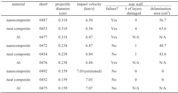
Table 1.Experiments for evaluation of the composites as rear wall
material shot# projectile
diameter (cm)
impact velocity
(km/s) failure? rear wall # of layers delamination. damaged area (cm2)
nanocomposite 0487 0.318 6.50 Yes 4 56.7
0453 0.318 6.54 Yes 4 63.6
Al 0477 0.318 6.47 Yes N/A N/A
nanocomposite 0472 0.238 6.87 No 1 40.7
neat composite 0454 0.238 6.84 No 1 43.0
Al 0476 0.238 6.84 Yes N/A N/A
nanocomposite 0492 0.159 7.01(estimated) No 0 0
neat composite 0452 0.159 7.03 No 0 0
Fig. 3. Ultra-high speed camera image of debris cloud development from hypervelocity impact by 0.238cm Al projectile on 0.05cm thick 6061 Al plate; Rice shot#0472. The image has two frames, 3μs apart. The debris cloud goes onto impact the nanocomposite rear wall.
Fig. 4. Post-mortem photographs of rear walls from set Aexperiments. All images are front-faces of the rear walls, except for the central image (#0454) which is the back-face of the rear wall illustrating nonff -failure (i.e. no perforations) of the neat composite. The front-face of that rear wall looks similar to that of #0472. The back-face of rear wall from #0472 looks similar to #0454 (i.e. it also has no perforations). Scale on the left of each photograph is in centimeters.
Spherical Al projectiles of diameters 0.318cm, 0.238cm and 0.159cm were launched onto Al bumpers to create debris clouds to impact the composites and the similar-areal-density Al sheets. Theset Aexperiments and their results are summarized in Table 1. Fig. 3 captures the development of a debris cloud during one such experiment (Rice shot#0472). In the figure, there are two frames, 3μs apart, illustrating the growth of debris cloud from one instant to the other, right before impacting the rear wall (a nanocomposite sample in this case). To summarize the set A experiments, with 0.318cm projectiles, all 3 samples (nanocomposite, neat composite and Al) failed (i.e. complete penetration) from the debris cloud impacts. With 0.238cm projectiles, the nanocomposite and the neat composite did not fail, whereas the Al sheet failed. With 0.159cm projectiles, all 3 samples did not fail from the debris cloud impacts. Figure 4 is the collage of post-impact photographs of the rear walls from set A experiments. These results show that both the nanocomposites and the neat composites make better rear wall materials than the similar-areal-density Al sheets. Comparatively, the nanocomposites and the neat composites have similar performance, with comparable delamination area upon impact by the debris clouds (Table 1). With 0.5 wt% of SWCNT, the HVI performance of the epoxy/UHMWPE composite as rear wall does not show noticeable change.
3.2. Set B: Evaluation of Composites as Bumper Shields
Table 2. Experiments for evaluation of the composites as bumper
material shot# projectile .
diameter impact (cm) velocity (km/s) bumper impact hole diameter (cm) rear wall failure? damage area (cm2) witness plate failure? damage area (cm2) nanocomposite 0473 0.318 6.45 6.11 Yes 12.6 No 50.3
neat composite 0455 0.318 6.46 6.21 Yes 9.6 No 44.2
Al 0486 0.318 6.49 4.97 Yes 28.3 No 15.6
nanocomposite 0489 0.238 6.87 5.60 Yes 15.9 No 19.6
neat composite 0456 0.238 7.03 5.72 Yes 19.6 No 23.8
Al 0488 0.238 6.85 4.23 No 41.3 No None
Fig. 5. Ultra-high speed ca
Fig. 6. Post-mortem photographs of rear walls from set B experiments. The scale in each photograph is in centimeters.
Spherical Al projectiles of diameters 0.318cm and 0.238cm were launched directly onto the composites and the similar-areal-density Al sheets. The set B experiments and their results are summarized in Table 2. Fig. 5 illustrates the debris cloud characteristics of the nanocomposite (A), the neat composite (B), and the Al sheet (C) from HVI by Al projectiles. From the figure, it is evident that the characteristics of the debris clouds from the HVI on the nanocomposite and the neat composite are noticeably different from that of Al sheet. In comparison to HVIs of Al projectiles onto the composites, HVIs of Al projectiles onto Al sheets inflict smaller impact holes on the bumpers and produce debris clouds that are more expansive (larger in surface area) and have a characteristic shape with a defined dense leading front. This difference is important because a larger debris cloud deposits its energy over a larger area on the rear wall, thus increasing the likelihood of the rear wall resisting the impact without failure. The post-impact photographs of the rear walls (Fig. 6) show that, in addition to having smaller damage area, the debris clouds from the composite bumpers inflict holes that are significantly larger than the damage craters by the debris clouds from Al bumpers. This means that the debris clouds from composite bumpers contain larger particulates than the debris clouds from Al bumpers. The small area and large particulates of these debris clouds from the composite bumpers are undesired of a bumper shield. In addition, it should be noted that total mass of debris clouds falls monotonically with increasing density of bumper material when equal bumper areal densities are maintained (after Hopkins and Swift [11]). This means that the mass of debris cloud from Al bumper is smaller than that from the composite bumpers owing to higher density of Al. To summarize the debris cloud properties, the debris clouds from the composites have smaller area and carry more mass with larger particulate sizes than the debris clouds from Al bumper. This is the reason for the non-failure of the rear wall in shot#0488 (Al sheet as bumper) from the debris cloud impact, and the failure of the rear walls in shot#0489 (nanocomposite as bumper) and shot#0456 (neat composite as bumper). Hence, the similar-areal-density Al sheet performs better than both types of composites as a bumper shield material. These results are consistent with the results obtained by Christiansen [12] and Schonberg [n 13] on graphite/epoxy composite bumpers.
Comparatively, the nanocomposites and the neat composites perform similarly to each other. For similar HVIff experiments, the impact-hole size on the bumper, the damage type and damage area on the rear wall and witness plates are all similar to one another. The debris cloud images have similar characteristics (Fig. 5). From the observations, it is
concluded that with 0.5 wt% of SWCNT in the nanocomposite, the presence of SWCNT does not change the HVI response of the epoxy/UHMWPE composite bumper.
4. Conclusion
Composites of UHMWPE fabrics with epoxy matrix and SWCNT (0.5 wt% of the fabric) were prepared to study their HVI characteristics at impact velocities in the 6.5 to 7 km/s range. In one set of experiments, these nanocomposites were impacted with debris clouds from HVI penetration of spherical Al projectiles on Al plates in order to assess their HVI response as a rear wall in a Whipple shield configuration. In another set of experiments, the nanocomposites were impacted directly with spherical Al projectiles at hypervelocities to assess their HVI response as a bumper shield. Similar experiments were carried out with epoxy/UHMWPE without nanotubes (or, neat composites) and with Al sheets having areal density similar to that of both the composites. The results show that nanocomposite and the neat composite perform better as rear walls than the Al sheets, but are lesser effective bumper shields. Comparatively, the two composites perform similarly to one another as rear walls and as bumper shields. In this preliminary work, SWCNT were not functionalized and no special efforts were made to improve the dispersion of SWCNT in the polymer resin. For these epoxy/UHMWPE composite samples, the results show that reinforcement with 0.5 wt% of non-functionalized SWCNT has no noticeable effect on their HVI response.
Acknowledgements:
This project is supported by NASA-JSC Grant # NNX10AR05G. The authors are thankful to Jay Laughman (NASA-JSC; Jacobs Engineering) for his direct assistance in the operation of the two-stage light gas gun.
References
[1] Thakre, P.R., Lagoudas, D.C., Riddick, J.C., Gates, T.S., Sarah-Jane V. Frankland, S.V., Ratcliffe, J.G., Zhu, J. and Barrera, E.V. fiber
Journal of Composite Materials 45(10), (2011) 1091 1107.
[2] Chakravarthi, D.K., Khabashesku, V.N., Vaidyanathan, R., Blaine, J., Yarlagadda, S., Roseman. D., Zeng, Q., and Barrera, E.V. Carbon Fiber Bismaleimide Composites Filled with Nickel-Coated Single-Walled Carbon Nanotubes for Lightning- Advanced Funcional Materials 21, (2011) 2527 2533.
[3]
International Journal of Impact Engineering35 (2008) 1606 1611.
[4] Clark, Protecting Earth-orbiting spacecraft against micro-meteoroid/orbital debris impact damage using composite structural systems and materials: An overview Advances in Space Research 45 (2010) 709 720.
[5] International Journal of Impact
Engineering17 (1995) 751 762.
[6] Journal of Reinforced Plastics and
Composites25 (11), (2006) 1215 1221.
[7] Lamontange, C., Manuelpillai, G.N., Taylor, E.A., Tennyson, R.C. Normal and oblique hypervelocity impacts on carbon fiber/peek
International Journal of Impact Engineering23 (1999) 519 532.
[8] Lamontange, C., Manuelpillai, G.N., Kerr, J.H., Taylor, E.A., Tennyson, on
hyperveloc International Journal of Impact Engineering 26 (2001) 381 398. [9] May, C.A., Epoxy Resins: Chemistry and Technology, 2nd ed., Marcel Dekker Inc., New York (1987).
[10] Prevorsek, D. C. Structural Aspects of the Damage Tolerance of Spectra Fibres and Composites, in Oriented Polymer Materials (ed S. Fakirov), Wiley-VCH Verlag GmbH, Weinheim, Germany. (2008) doi: 10.1002/9783527615056.ch15.
[11]
Technical Report AFML-TR-68-257. (1968).
[12] -163, Eagle Engineering Inc.,
Houston, Texas, 1987.