Contents lists available at ScienceDirect
International
Journal
of
Solids
and
Structures
journal homepage: www.elsevier.com/locate/ijsolstr
Numerical
analysis
on
the
elastic
deformation
of
the
tools
in
sheet
metal
forming
processes
D.M. Neto
a,∗, J. Coër
a,b, M.C. Oliveira
a, J.L. Alves
c, P.Y. Manach
b, L.F. Menezes
aaCEMUC,DepartmentofMechanicalEngineering,UniversityofCoimbra,PoloII,RuaLuísReisSantos,PinhaldeMarrocos,3030-788Coimbra,Portugal bUniv.BretagneSud,FRECNRS3744,IRDL,F-56100Lorient,France
cCMEMS,MicroelectromechanicalSystemsResearchUnit,UniversityofMinho,CampusdeAzurém,4800-058Guimarães,Portugal
a
r
t
i
c
l
e
i
n
f
o
Articlehistory: Received 1 April 2016 Revised 13 July 2016
Available online 28 August 2016 Keywords:
Reverse deep drawing Tools deformation Finite element analysis Material flow DD3IMP
a
b
s
t
r
a
c
t
Theformingtoolsarecommonlyassumedasrigidinthefiniteelementsimulationofsheetmetal form-ingprocesses. Thisassumptionallows tosimplify the numericalmodel and, subsequently,reducethe requiredcomputational cost.Nevertheless,the elasticdeformation ofthetools caninfluence consider-ablythematerialflow,specificallythedistributionoftheblank-holderpressureovertheflangearea.This study presentsthefiniteelementanalysisofthereversedeepdrawingofacylindricalcup,wherethe formingtoolsaremodelledeither asrigidorasdeformablebodies.Additionally,thenumericalresults arecomparedwiththeexperimentalones,inordertoassesstheaccuracyoftheproposedfiniteelement model.Consideringthe elasticdeformation ofthetools,thenumericalresults areinbetteragreement withtheexperimentalmeasurements,namelythecupwallthicknessdistribution.Ontheotherhand,the computationaltimeofthesimulationincreasessignificantlyincomparisonwiththe classicalapproach (rigidtools).
© 2016ElsevierLtd.Allrightsreserved.
1. Introduction
The sheetmetal forming processesare commonlyused inthe automotiveindustrytoproduceseveralbodypanels.Nevertheless, thehigh competitively in the currentworld market hasled to a strong reduction of the development periods in the car manu-facturing industry (OECD, 2011). Thus, the empirical tool design methods based on trial-and-error procedures has been gradually replacedbythevirtual productconceptionusingnumerical simu-lation(Dilleretal.,1997;Marioetal.,2013).Indeed,thefinite ele-mentsimulationofsheetmetalformingprocessesiscurrentlyused inmanycompaniestopredictformingdefects,suchasnecking(or fracture)(Mattiassonet al., 2014; Msolli etal., 2015), springback (Chalaletal., 2012;Ghaei,2012)orwrinkling(Netoetal.,2015b). Thecontinuousdevelopmentofthesenumericaltoolsoverthelast 40yearsreachedanincontestablelevelofmaturity,providing reli-ableresults(Chenotetal.,2014).Nevertheless,inordertodecrease thediscrepancybetweenexperimentalandnumericalresults, sev-eraleffortshavebeenmadetoimprovetheaccuracyofthe
numer-∗ Corresponding author. Fax: +351239790701.
E-mail addresses: [email protected] (D.M. Neto), [email protected] (J. Coër), [email protected] (M.C. Oliveira), [email protected] (J.L. Alves), [email protected] (P.Y. Manach), [email protected] (L.F. Menezes).
icalmodels,namelythedevelopmentofnewmaterialconstitutive modelsaccountingforboththeanisotropyandthekinematic hard-eningeffects(Chenetal.,2016;Leeetal.,2016;Taherizadehetal., 2015;Yoonetal.,2014).
Typically, the forming tools are assumed as rigid in the fi-niteelementsimulationofsheetmetal formingprocesses.This al-lows simplifying the mechanical problem under analysis, specif-ically the numerical treatment of the frictional contact between the deformable sheet and the tools. However, the actual trend in the automotive industry of increasing application of advanced highstrengthsteelsin thebodies-in-white,dictatesthat the con-tactforcesarisingintheformingtoolsaresignificantlyhigher(Xu et al., 2012). Thus, this newparadigm can requirethe update of the numericalmodels toincorporatethe elasticproperties ofthe tools (Choi et al., 2013; Del Pozo et al., 2007). The adoption of the penalty method with a surface stiffness variable across the surfaceof the toolsprovides an approximation for its elastic de-formation (Hallquist, 2007). However, the elastic deformation of thetoolsisgovernedboth bythemagnitudeofthecontactforces arising onits surface,the completegeometryofthe toolsandits mechanical properties. Therefore, the accurate prediction of the tools deformation requires the modelling of the entire tool ge-ometry (volume instead of surface). Nevertheless, the discretiza-tion of the tools with finite elements implies a considerable in-creaseof the computational cost.In order toreduce the number http://dx.doi.org/10.1016/j.ijsolstr.2016.08.023
of the degrees of freedom (DOF) involved, and hence the com-putational cost, the classical static condensation method can be adopted(Hoffmann,2005),whichcanbeonlyapplicabletolinear andsmallstrain problems.Accordingly,onlythesurfacegeometry ofthetoolsisdiscretized(theonlyofinterestforcontactanalysis), whileallinternalDOFareeliminatedbycondensation.An alterna-tiveapproachisthemodalreductiontechnique,whichisbasedon the calculation ofthe eigenvalues, where the linear combination ofpre-calculateddeformationmodesleadstothedesiredfinal de-formation(LingbeekandMeinders,2007).Thisisanapproximated method,wheretheaccuracyisdefinedbythenumberof deforma-tionmodesused(Strucketal.,2008).
Großmannetal.(2009)proposedaniterativemethodtoadjust theshapeoftheformingtoolstocompensate itselastic deforma-tion.Theresultsshowasignificantinfluenceofthetooldeflection inthedraw-in,mostlyduetothedistributionoftheblank-holder force,whichishigheronthediecorners(Chenetal.,2012).Onthe other hand,since the elasticdeformation ofthe toolsaffects the contact conditionsbetween the sheetand the forming tools,the resultspresentedbyKeumetal.(2005)show thatthespringback predictionisimprovedwhenconsidering thetoolsdeformationin thenumericalmodel.Inthestudyconductedby DoegeandElend (2001), theytake advantageoftheelasticdeflectionofthe blank-holdertoenlargethesafeworkingareaandimprovethequalityof theproduceddeepdrawingparts.Thepliableblank-holderisable to adjust to the changes in sheet thicknessoccurring duringthe forming process,providing a uniformpressuredistribution inthe flange,whichimprovesthematerialflow.
This studyintends to analyse the influenceof the tools mod-elling (rigid or deformable) in the accuracy of the numerical re-sults, namely the contact forces and the thickness distributions. The reversedeep drawingofa cylindricalcup istheexample se-lected, which was proposed as benchmark at the Numisheet’99 conference(GelinandPicart,1999).Thisformingprocesshasbeen selected due to the process conditions adopted, i.e. the clear-ance between the die and the blank-holder is kept constant us-ingscrews andadjustablewashersin-between.Furthermore, typi-cally themulti-stage drawingprocessesare moredifficultto sim-ulateaccuratelybecausethestress andstraindistributions result-ing from the first stage will influence the subsequent behaviour (Thuillieretal.,2002).Theorganizationofthepaperisthe follow-ing:theequationsdefiningtheconstitutivemodelofthesheetare recalledin Section2, whilethefrictional contactproblemis pre-sentedinSection3,considering boththeassumptionofrigidand deformableformingtools.Boththeexperimentalsetupandthe de-velopedfiniteelementmodelofthereversedeepdrawingprocess aredescribedinSection 4,includingthecomparisonbetween nu-mericalandexperimentalresults,highlightingtheinfluenceofthe toolsdeformationintheaccuracyofthenumericalpredictions.The mainconclusionsofthisstudyarediscussedinSection5. 2. Constitutivemodel
The constitutive material model establishes the relationships betweenthemostrelevant statevariables characterizingthe con-tinuum medium. In the present study, the deformation of the metallic sheet is described by a rate-independent elastoplastic material model. The material mechanical behaviour is assumed linear and isotropic in the elastic domain and non-linear and anisotropicintheplasticdomain(orthotropicplasticity).According toBelytschko etal.(2000),forhypoelastic materialstheenergyis not conservedin aclosedelastic deformation cycle.Nevertheless, assuming thatelastic strainsare smallcomparedtoplasticstains, the adoptionof ahypoelastic-plastic modelprovides an adequate elastic response, with negligible errorin the conservation of en-ergy. In thistype ofconstitutive models,the strain ratetensoris
decomposedadditivelyby:
D=De+Dp, (1)
whereDeandDp denotetheelasticandplasticstrainratetensors,
respectively.Thus,theelasticresponsespecifiedinthedifferential formisgivenby:
˙
σ
=Ce:De, (2)where
σ
˙ is the Cauchy stress rate (objective derivativesmust be used,e.g.Jaumann’sderivative)andCedenotesthecorrespondingfourth-ordertensor ofelasticmoduli. Thedifferential formofthe constitutive Eq. (2) must satisfy the objectivity condition, which isguaranteed writingthe equationsinan appropriate orthogonal rotatingframe(Dafalias,1985).TherateofvariationoftheCauchy stresstensoraccordingwiththeJaumannderivativeisdefinedby:
˙
σ
J=σ
˙ +σ
W−Wσ,
(3)whereWisthetotalspintensor(antisymmetricpartofthe veloc-itygradient tensorL). Assuminglinearisotropicelasticbehaviour, thefourth-ordertensorofelasticconstantsisgivenby:
Ce=
λ
II+2μ
I4, (4)
where
λ
andμ
are the Lamé parameters, I is the second-order identitytensorandI4 isthefourth-orderidentitytensor.In order to describe the plastic response of the material it is necessary to define: (i) a yield function; (ii) a flow rule and (iii) a hardening law. The yield criterion accounts for the plas-ticanisotropy ofthemetallic sheet, boundingtheelastic domain. The evolution ofthe yield surfacedepends ofthe hardening law adopted.Indeed,itsexpansionisdictatedbyanisotropichardening law,whileitscentretranslationisdictatedbyakinematic harden-inglaw.Thus,theyieldconditionisdefinedbytheyieldcriterion andthehardeninglawthroughtheyieldfunction:
F
(
σ,
¯ Y)
=σ
¯−Y =0, (5)where
σ
¯ istheequivalentstressandYdenotes theflowstress in simpletension,whichdependsontheeffectiveplasticstrain.The equivalentstressdependsoftheyieldcriterionadopted,whilethe flowstressYdependsofthehardeninglawadopted.Nevertheless, theequivalentstressisfullydefinedbythedeviatorcomponentof theCauchystresstensorσ
,theback-stresstensorXandthesetof internalvariablesoftheconsideredyieldcriterionα
:¯
σ
=σ
¯(
σ
−X,α
)
, (6)where
σ
−X denotes the effective deviatoric stress tensor. The back-stresstensor X isa deviatoric,symmetric second-order ten-sor,which dependsofthe kinematichardening lawadopted.The adopted constitutive model considers an associated inviscid flow rule,whichdefinesthedirectionoftheplasticstrainratethrough thegradientoftheyieldfunction:Dp=
λ
˙V=λ
˙∂
F∂
(
σ
−X)
, (7)where
λ
˙ denotes the plastic multiplier and V is the first deriva-tiveoftheyieldconditioninordertotheeffectivedeviatoricstress tensor(MenezesandTeodosiu,2000).Theplasticmultiplieris de-terminedbyenforcingtheconsistencycondition:˙
F=
∂
∂
Fσ
:σ
˙ +∂
∂
Fα
:α
˙ =0, (8)whereF˙ is thetime derivative of theyield condition (5). In the presentstudy,theisotropicwork hardeningbehaviour,which de-scribestheevolutionoftheflowstresswithplasticwork,is mod-elledbytheSwiftlaw:
Y=K
(
ε
0+ε
¯p)
n withε
0= Y 0 K 1/n , (9)whereK,ɛ0 andnare thematerial parameters, while
ε
¯p denotestheequivalentplasticstrainandY0 denotestheinitialvalueofthe
yield stress. The slope of the hardening curve is defined by the plasticmodulus:
H=
∂
Y/∂
ε
¯p, (10)whichdependsontheadoptedhardeninglaw(9).Theconsistency condition(8) canberewrittenconsideringgenericexpressions for theisotropichardeninglawandoftheyieldcriterion:
˙
F=V:
(
σ
˙ −X˙)
−Hε
¯˙p=0, (11)where
ε
¯˙pdenotestheequivalentplasticstrainrate,suchthatε
¯˙p=˙
λ
.The amount of springback predicted by the numerical simu-lationis strongly affected by the Bauschinger effect(Chun etal., 2002),whichisnumericallydescribedbymeans ofthekinematic hardeningconceptintroducedbyPrager(1949).Thekinematicpart ofthe work hardening, i.e. thenon-linear evolution of the back-stresstensorX,isdescribedbythenon-linearlawwithsaturation proposedbyFrederickandArmstrong(2007),givenby:
˙ X=CX
Xsat ¯σ
(
σ
−X)
−X ˙ ¯ε
p with X(
0)
=0, (12)whereXsatcharacterizesthesaturationvalueofX,whilethe
mate-rialparameterCXcharacterizestherateofapproachingthe
satura-tion.Thisevolutionlawiswidelyusedtodescribethebackstress’s evolution,sinceitprovidesaccuratepredictionsoftheBauschinger effect(Griloetal.,2016).
2.1.Anisotropicyieldfunction
Therollingoperationusedinthemanufactureofmetallicsheets inducesanisotropyinthemechanicalproperties.Inordertomodel thisbehaviourofthemetallicsheet,theHill’squadraticyield func-tionhavebeenconsidered(Hill,1948),whichiswidelyusedinthe sheetmetalformingsimulationofsteels(Dasappaetal.,2012).The extension ofthe isotropicvon Mises yieldcriterion to anisotropy proposedbyHill(1948)isgivenby:
¯
σ
2=(
σ
−X)
:M:(
σ
−X)
, (13)where
σ
¯ isthe equivalentstressandM denotes thefourth-order symmetrictensor, whichtakesinto account theorthotropic sym-metryofthematerial.Duetotheincompressiblecharacterof plas-ticity,the yield criterion depends onlyof the effective deviatoric stresstensorσ
−X,whereσ
isthedeviatoroftheCauchystress tensor and X is the back-stress tensor. The parameters that de-scribetheanisotropyofthematerial,i.e.thevariationintheyield stressandther-valueswiththein-planeorientation,arecontained inthedefinitionofthistensor.Accordingly,theHill’48yield crite-rion,definedintheappropriateorthogonalrotatingframe,isgiven by: ¯σ
2=F(
σ
22−X22−σ
33+X33)
2+G(
σ
33−X33−σ
11+X11)
2 +H(
σ
11−X11−σ
22+X22)
2+ +2L(
σ
23−X23)
2+2M(
σ
13−X13)
2+2N(
σ
12−X12)
2, (14)where F, G,H, L, M and N are the parameters that describe the anisotropy of the material.
σ
11,σ
22 andσ
33 denote the devia-toricCauchystresscomponentsintherolling,transverseand thick-nessdirections,respectively,whileσ
12,σ
23 andσ
13aretheshearstressesinthethree orthogonal directionsrespectively.According with(7),theassociatedflowrulefortheHill’48yieldfunction(13) canbewrittenas:
Dp=
λ
˙ M:(
σ
−X)
¯σ
, (15)whichdefinesthedirectionoftheplasticstrain rate.The second-orderderivativeofthequadraticanisotropicyieldcriterion(Hill’48) inordertotheeffectivedeviatoricstresstensor,isgivenby:
Q=
∂
2σ
¯∂
(
σ
−X)
2 = Mσ
¯−(
M:(
σ
−X))
V ¯σ
2 . (16) 2.2. TimeintegrationThe implementation of the combined isotropic and kinematic hardeninglawspreviouslydescribedintoanimplicitfiniteelement code is briefly outlined. The time integration of the constitutive lawallowstoevaluate,ineach point,theequivalentplasticstrain increment, the newstress state tensorandall state variables de-pendentonthesetwoquantities.Thehypoelastic-plastic constitu-tive modelforlarge straincan be writteninthe formofalinear relationbetweentheobjectivemeasuresofthestressrateandthe strainrate:
˙
σ
J=Cep:D, (17)where Cep is a fourth-order tensor that defines the elastoplastic
modulus.Theexpressionforthistensordependsofthealgorithms adopted in the integration of the constitutive model and on the type of relation considered between the states at the beginning andattheendoftheloadingincrement.Thus,itispossibleto con-sider the tangent elastoplastic modulus or the consistent elasto-plasticmodulus(Alves,2003).
The tangent elastoplastic modulus establishes the relationship betweenthe Cauchy stress ratetensorandthe strain ratetensor, definedas:
Ceptan=Ce−
α
f0VV, (18)
where
α
takes the value 0 in the elastic domain, while for an elastoplasticincrementitsvalueisequalto1.Theparameterf0de-pendsontheisotropicandkinematichardeninglawsadopted.For theFrederick-Armstronglawisgivenby:
f0= 4
μ
2 2μ
V:V+CXV: Xsat ¯ σ(
σ
−X)
−X+H , (19)whereVandH aregivenexplicitlyby(15) and(10),respectively (Alvesetal.,2007).
The consistent elastoplastic modulus establishes the relation-shipbetweentheincrementalCauchy stresstensorandthe incre-mentalstraintensorforagiventimeincrement.Thebackward Eu-lertime integrationalgorithm is commonlyadopted (Grilo et al., 2016),whichusesthetimederivativesattheendoftheincrement (SimoandTaylor,1985).Thetemporalintegrationoftheelastic re-sponse(differentialformspecifiedin(2))overtheabovementioned timeinterval
tallowstoevaluatethestressincrementas:
σ
f−σ
0=Ce:ε
e=Ce:(
ε
−ε
p)
, (20)where the subscripts f and0 are used to refer the quantities at theendandatthebeginningoftimeincrement, respectively.The total strain tensorincrement
ɛ andthe plasticstrain increment
ɛp are calculatedby means ofintegrationofthetotal and
plas-ticstrainratetensors,overthetimeincrement
t.Integratingthe adoptedkinematichardeninglaw(12)inthesametimeincrement andsubtractingtheresultto(20),itcanbewritten:
σ
f−Xf=σ
0−X0+2μ
ε
−2μ
ε
p−
Xσ
sat¯(
σ
f−Xf
)
−X0(
1−e−CXε¯p)
, (21)where the plastic strain increment is given by the middle point rule using a fully implicit approximation (Hughes and Winget, 1980):
ε
p=λ
V-300 -200 -100 0 100 200 300 400 500 -0.5 -0.4 -0.3 -0.2 -0.1 0 0.1 0.2 0.3 0.4 0.5 ] a P M[ s s ert s r a e h s , s s ert s e ur T
True strain, amount of shear Uniaxial tensile
Simple shear Bauschinger shear Numerical
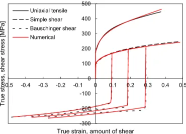
Fig.1. Comparison of the stress–strain curves predicted by the constitutive model with the experimental ones for uniaxial tensile test, monotonic simple shear and reversed simple shear tests after 10%, 20% and 30% forward shearing.
Thelinearizationof(21)inthevicinityofthefinalconfiguration allowstodefinetheconsistentelastoplasticmodulusforthe kine-matichardeninglawadoptedas(foranarbitraryisotropic harden-inglawandyieldcriterion):
Cepcon=Ce−4
μ
2(
1−β
)
V fVf Hf +¯
ε
pQ f, (23)
wheretheparameter
β
isusedtodecomposethestrainincrement into theelastic andelastoplastic components that occurover the timeincrementt.Thetensor
dependsonthekinematic hard-eninglawadoptedintheconstitutivemodel,beingdefinedforthe Frederick-Armstronglawby:
−1=
σ
¯ +Xsat 1−e−CXε¯p ¯σ
I4+2μ
V fVf Hf +¯
ε
pQ f + +CXe−CXε¯ p Hf Xsat ¯σ
(
σ
f−Xf)
−X0 Vf, (24)whereQrepresentsthesecond-orderderivative oftheyield crite-rioninordertotheeffectivedeviatoricstress tensor,givenin(16) fortheHill’48yieldcriterion(Alvesetal.,2007).
2.3. Materialparametersidentification
The deepdrawingquality (DDQ)mild steelisthematerial se-lectedfortheblank.Theelasticbehaviourisassumedisotropicand constant,whichisdescribedbytheHooke’slawwithYoung’s mod-ulusof210GPaandPoissonratioof0.30.Regardingtheplastic re-sponse,theconstitutiveparametersofthehardeninglaw(isotropic andkinematic)andyieldcriterion(associatedflowrule)are calcu-latedfromexperimentaltests(Thuillieretal., 2010). Thematerial parameters are identifiedby the bestfit totheexperimental val-ues,minimizingacostfunctionusingleastsquaresestimation.
The identificationprocedureadopted forthematerial parame-tersinvolvedinthehardeninglawshasbeendetailedbyHaddadi et al. (2006). The set of experimental tests used is: (i) uniaxial tensiletestalongtherollingdirectionuptolocalizednecking;(ii) monotonicsimplesheartestsalongtherollingdirectionupto50% amountofshearand(iii)Bauschingersimplesheartestsalongthe rolling direction, after 10%, 20% and 30% amount of monotonic shear. The experimental stress–strain curve of each above men-tionedtest is presentedin Fig.1. Theprocedure used toidentify thebest setofconstitutiveparametersisbased onthe minimiza-tionofanerrorfunctionthatevaluatesthedifferencebetweenthe
Table1
Material parameters for the isotropic–kinematic hardening described by Swift law.
Y0[MPa] K[MPa] n CX Xsat[MPa] 172 .0 500 .8 0 .20 2 .2 68 .2 Table2
Anisotropy parameters for the Hill’48 yield criterion.
F G H L M N
0 .314 0 .366 0 .634 1 .500 1 .500 1 .176
predictedandtheexperimentalstressvalues(Dasappaetal.,2012). Accordingly,theoptimizationproblemconsistsindeterminingthe setofmaterialparameters A,whichminimizesthefollowingcost function: F
(
A)
= nt i=1 1 mi mi j=1 wi jσ
i jsimσ
i jexp −1 2 , (25)where nt is the number of different tests, mi is the number of
measured points of the ith test,
σ
denotes the tensile or shear stressandwistheweightassociatedwitheachstresspoint.Inthe presentstudytheweightingfactorsareconsideredequalto1.The superscripts “sim” and “exp” denote the simulation and experi-mentaldata,respectively.Theobtainedmaterialparametersforthe isotropic hardening describedby the Swift law(9) and the non-linearkinematichardeningdefinedbytheFrederick-Armstronglaw (12)arelistedinTable1.Theinclusionofthenon-linearkinematic hardeningimprovestheaccuracyofthesheetmetalforming simu-lation,whentheplasticdeformationoccursincyclicloadingpaths (Taherizadeh etal., 2015). The comparisonbetweenexperimental andnumericalstress–straincurvesisalsopresentedinFig.1.The adopted constitutive model allows describing accurately the me-chanical behaviour ofthe mild steel.Indeed,both themonotonic andcyclic stress–strain curves obtained by the numerical model are ingood agreementwiththe experimental ones, although the modeldoesnot allow to describe thework hardening stagnation (YoshidaandUemori,2002).Theorthotropicbehaviourofthemildsteel(DDQ)isdescribed in the present study by the classical Hill’48 yield criterion. The most common method of determining the parameters of Hill’48 yield criterion is based on the Lankford coefficients (Dasappa etal., 2012).Accordingly,theanisotropy parametersareevaluated throughthefollowingrelations:
H G =r0; F G = r0 r90 ; N G =
r45+ 1 2 r 0 r90 +1, (26)wherer0,r45 andr90 arether-valuesobtain‘edexperimentallyby
uniaxialtensiletestscarriedoutalong0º,45ºand90ºtotherolling direction(Thuillieretal.,2010).Sincetheidentificationofthe ma-terialparameters forthehardeninglaw(see Table1) wascarried outusingthestress–straincurvesobtainedforspecimensoriented alongthe rollingdirection(RD),the yield stressvalue considered intheidentificationoftheyieldcriterion parameterscorresponds to the one obtained forthe uniaxial tensiletest performedwith thespecimenorientedalongRD(Netoetal.,2014a).Therefore,the conditionG+H=1is introducedinorder toevaluatethe param-eters F, G, H andN. The identified anisotropy parameters of the Hill’48 yield criterion are presented in Table 2. The sheet is as-sumedisotropicthroughthethickness, leadingtoL=M=1.5. The in-planeevolutionofther-valuepredictedbytheHill’48yield cri-terion ispresented in Fig.2, which iscompared with the exper-imental values.Furthermore,the uniaxial yield stress values
pre-0 0.5 1 1.5 2 2.5 0 20 40 60 80 100 120 140 160 180 200 0 15 30 45 60 75 90 r -value ] a P M[ s s ert s dl ei y eli s n e T
Angle from rolling direction [º] Experimental (yield stress) Hill'48 (yield stress) Experimental (r-value) Hill'48 (r-value)
Fig.2. Tensile yield stress and r-value in the sheet’s plane for the DDQ mild steel: comparison between the experimental values and the ones obtained considering the Hill’48 yield criterion.
Fig.3. Notation adopted in the definition of the two-body frictional contact prob- lem undergoing finite deformation.
dicted for different orientations with RD are also presented and comparedwiththeexperimentalvalues.
3. Contactmechanics
The numericalsimulationofsheetmetal formingprocesses re-quiresthe definition ofthe frictional contactconditions between theformingtoolsandthemetallicsheet.Sincethestiffnessofthe formingtoolsissignificantlylargerthantheoneoftheblank,they areusually assumedasrigidinthenumerical model,allowingto simplifytheproblemformulation(Heege andAlart, 1996). Never-theless, all contact problems are inherently non-linear since the contacting surface on which the loads are transferred from one bodytoanotherisunknownapriori.
3.1.Contactconstraints
The formulationfor3Dcontactproblemsundergoingfinite de-formation andlarge sliding is briefly summarized. Considering a two-body frictional contact problem, as illustrated in Fig. 3, the currentconfigurationofeachbody iisobtainedbyapplyingthe
deformationmapping
ϕ
itothereferenceconfiguration i0.The
su-perscripti=1andi=2indicatesbody1andbody2,respectively. Theboundariesofthetwo bodiesinthecurrentconfigurationare dividedintothreedisjointsets:
γ
iu,
γ
σi andγ
cidenotingtheDirich-letboundary(prescribeddisplacements),Neumannboundary (pre-scribedtraction)andthepotentialcontactboundary,respectively.
In order to define the fundamental kinematic andstatic vari-ablesof thecontact problem, thebody 1 isreferred as theslave body(slavesurface
γ
1c) andthebody 2isreferred asthe master
body(master surface
γ
2c). The normalgapfunctionexpressed for
anymaterial point onthe slave surfacexs∈
γ
1c is definedas
fol-lows:
gn=
(
xs−¯xm)
·¯n, (27)where ¯ndenotes thecurrentoutwardnormalvector onthe mas-ter surfaceattheprojection point ¯xm,evaluated accordingtothe
closestpointprojectionoftheslavepointontothemastersurface (KonyukhovandSchweizerhof,2008).Accordingly,thevalueofthe normalgapfunction isnegativewhentheslavepointis penetrat-ingthemasterbody,whichisphysicallyinadmissible(Pietrzakand Curnier,1999).Forsakeofsimplicity,allquantitiesevaluatedatthe projection point are denoted by a bar overit. The change ofthe closest point projection definestherelative tangentialsliding be-tweencontactsurfaces.Thus,thetangentialslipvectorisgivenas follows:
gt=
τ
¯αξ
α, (28)where
τ
α denotes the covariant tangential basis vectors on the parameterized master surface, evaluated at the projection point, whileξ
=(
ξ
1,ξ
2)
are the convective coordinates of theparame-terizedmastersurface(LaursenandSimo,1993).
Consideringthelocallinearmomentumbalanceacrossthe con-tact interface, the action–reaction principle must be satisfied in each contact point, i.e. the contact force exercised by the slave body onthe mastersurfaceis equalandopposite to theone ap-pliedbythemasterbodyontheslave surface.Analogouslytothe kinematicvariables,thecontacttractionactingonthemaster sur-faceisdecomposedintonormalandtangentialcomponents:
t=pnn+tt, (29)
wherepn denotesthenormalcontactpressure.
The contact constraints in the normal direction are imposed through theunilateralcontactconditions, whichdefine the phys-ical requirements of impenetrability and compressive interaction between the bodies. Thesecontact constraints are known as the Hertz–Signorini–Moreauconditions:
gn≥0; pn≤0; pngn=0, (30)
wherethefirstindicatestheimpenetrabilityconstraint,thesecond imposes that the normal contacttraction is compressive andthe lastisthecomplementarityconditionbetweenthefirsttwo condi-tions.Assumingtheclassicalnon-associatedCoulomb’sfrictionlaw atthecontactinterface,thecontactconstraintsassociatedwiththe frictionlawaregivenasfollows:
tt−μ
|
pn|
≤0; tt−μ
|
pn|
gt
gt=0;
gt(
tt−μ
|
pn|
)
=0, (31)where
μ
denotesthecoefficientoffriction.Thefirstcondition indi-catesthestick/slipcontactstatus,i.e.imposesthatthemagnitude of thefriction force doesnot exceed the contactpressure multi-pliedbythefrictioncoefficient.Thesecondconditionindicatesthe slip rule,which defines that the friction force vector is collinear withthe tangentialslip vector. The last conditionis the comple-mentarity conditionbetween the first two conditions (Mijar and Arora,2000).Thenonlinear boundaryvalue problem(BVP) forthefrictional contactsystemundergoing finitedeformation, showninFig. 3,is statedasfollows:
div(
σ
i)
+bi=0, in i ti=σ
ini=¯ti, onγ
i σ ui= ¯ui, onγ
i u , (32)where
σ
i denotesthe Cauchy stress tensor(inertiaterms arene-glected). Furthermore,the bodiesare only subjectto body forces bi andprescribed boundary conditions,namelyapplied boundary
tractions ¯ti on the Neumann boundary and prescribed
displace-ments ¯ui onthe Dirichletboundary. Accordingly,the strongform
ofthetwo-bodyfrictionalcontactproblemisdefinedin(32), con-sideringthe contactconstraintsgivenin (30) and(31).The weak formulation of theBVP is obtainedusing the principle of virtual velocitiesproposedbyMcMeekingandRice(1975).
3.2. Augmentedlagrangianmethod
The frictional contact problem is regularized with the aug-mented Lagrangian method, originally proposed by Alart and Curnier (1991) to deal with frictional contact problems. This methodallowsanexactenforcementofthecontactconstraints de-fined through relations (30) and (31), while providing a smooth functional (Pietrzak andCurnier, 1999). Therefore, the minimiza-tion problemwithinequality constraintsis convertedinto afully unconstrained one, where the solution is the saddle point of a functional (minimize primal variables and maximize dual vari-ables).Inthepresentimplementation,theLagrangemultipliersare retainedasindependentvariablesinthecoupledproblem,i.e.both variables are updated simultaneously in a singleloop. This strat-egy has alsobeen adoptedby other authorsase.g. Cavalieri and Cardona(2015).
The augmented Lagrangian functional only related with fric-tionalcontactcontributioncanbewrittenas:
Lc
(
u,λ
)
=g nλ
n+ε
2|
gn|
2− 1 2ε
dist 2(
λ
ˆ n,−)
+gt·λ
t +ε
2gt 2 − 1 2ε
dist 2(
λ
ˆ t,Caugm)
, (33)where ɛ denotes the penalty parameter anddist(x, C) is the dis-tance betweenx andC. The Lagrange multipliers
λ
n andλ
trep-resentthenormalcontactforceandthefrictionforce,respectively. Hence,theaugmentedLagrangemultiplier,denotedbyahat,is de-finedas:
ˆ
λ
=λ
ˆnn+λ
ˆt=(
λ
n+ε
gn)
n+(
λ
t+ε
gt)
, (34)whichisdecomposedintothenormalandtangentialcomponents. TheextendedconeCaugmistheconvexsetdefinedbyextensionof
the friction cone to the positive half-line+, i.e.the set of
pos-itive values of the normal augmented Lagrange multiplier (Alart andCurnier,1991).
The solution of the frictional contact problem is obtained throughthevariationoftheaugmentedLagrangianfunctional.This leads to a mixed system of nonlinear equations involving both nodal displacements andcontactforces asunknowns.The exten-sion of the Newton–Raphson method to non-differentiable prob-lems arising from contact mechanics was investigated by Alart (1997) andHeegaard andCurnier (1993), developingthe general-izedNewtonmethod.Themainideaofthismethodistosplitthe system ofnonlinear equationsinto twoparts, i.e.a differentiable structural partFs anda non-differentiable contactpart Fc such
that:
F
(
u,λ
)
=Fs(
u)
+Fc(
u,λ
)
=0, (35)whereFs representsthevirtual work ofthetwo-bodysystemin
absenceofcontactandFcdenotesthevirtualworkduetothe
fric-tionalcontactforces,i.e.thevariationoftheaugmentedLagrangian functionaldefinedin(33).Accordingly,theapplicationofthe gen-eralizedNewtonmethodisstatedas:
∇
uF s(
ui)
+∇
uF c ui,λ
i∇
λFcui,λ
iui
λ
i =−F s(
u i)
+F c ui,λ
i , (36)wherei istheiterationindexand
∇
uFs denotesthetangent ma-trixof thecontacting bodies.The sub-gradients∇
uFc and∇
λFcare components of the generalized Jacobian matrices for primal anddualvariables.Thus,adifferentJacobianmatrixisderived ac-cordingtothecontactstatus(gap,stickorslip)ofthenode(Heege andAlart,1996;Netoetal.,2016).
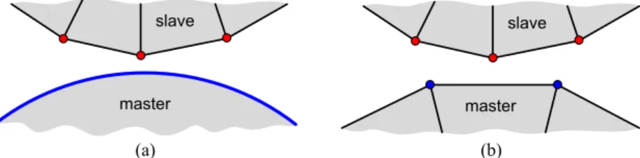
3.3.Node-to-segmentcontactelements
The node-to-segment discretization technique, widely used in contactproblemsundergoing finite deformation andlarge sliding (ZavariseandDeLorenzis,2009),isadoptedinthepresentstudy. It is associated with the master–slave approach (Hallquist et al., 1985), dictating the enforcement of the contactconstraints (uni-lateralcontactconditionandfrictionlaw)onlyintheslavenodes. Consequently,each contactelement iscomposed by aslave node andthe corresponding segment onthe master surface, asshown inFig. 4.Since the frictionalcontact constraintsare treatedwith theaugmentedLagrangian method,each contactelement is com-plementedbyanartificialnodetostorethecontactforce(Lagrange multipliers). Nevertheless, the transmission of the contact forces throughthecontactinterfaceonlyoccursforcontactbetween de-formablebodies(Netoetal.,2015).Theapproximationofthestiffer contactingbodybyarigidsurfacedoesnotrequiresthespatial dis-cretizationofthebody,thus noadditionaldegreesoffreedomare involved.Inorder toimprovethe accuracyandrobustnessof the numericalsimulation, in the present studythe master surface is smoothedwithNagatapatches(Netoetal.,2016,2014b).
In analogy to the internal forces of a classical finite element, theinternalforcevectorforasinglecontactelementderivedfrom the augmented Lagrangian method (Cavalieri and Cardona, 2015; HeegeandAlart,1996)isdefinedby:
Fc
u,λ
=⎧
⎪
⎪
⎪
⎨
⎪
⎪
⎪
⎩
projR− ˆλ
n n+projCaugmλt
−projR− ˆλ
n n+projCaugmλt
−1/ε
λ
n−projR− ˆλ
n n−1/ε
λ
t−projCaugmλt
⎫
⎪
⎪
⎪
⎬
⎪
⎪
⎪
⎭
, (37)wherethefirstlineis connectedwiththeslavenode, thesecond onerepresentsallnodescomposingthemastersegment,whilethe last one presents the additional equations necessary to evaluate thefrictionalcontactforces(intheslavenode).Incaseofcontact witharigidobstacle,thecontactforcesarisingintheslavenodes arenottransferredtothemastersurface,leadingtoasimplerform oftheresidualvector,i.e.thesecondlineof(37)vanish(Heegeand Alart,1996).
Theelemental contributionofa contactelement to theglobal right-hand side vector of the equilibrium equations depends on thecontact status(gap, stick orslip). The gapstatus (absence of contact) is defined by the normal component of the augmented Lagrange multiplier through the condition ˆ
λ
n>0. In this case,proj−
(
ˆλ
n)
=0 and projCaugm(
ˆλ
t)
=0, where the contribution ofthiscontactelementtotheinternalcontactforcevectoryields:
Fcgap
(
u,λ
)
= 00
−
λ
/ε
. (38)The stick contact status is defined by the condition
λ
ˆt< −μ
λ
ˆn, leading to proj−
(
λ
ˆn)
=λ
ˆn and projCaugm(
λt
ˆ)
=λt
ˆ . There-fore,from(37)thecontributiontotheinternalcontactforcevector yields: Fc stick(
u,λ
)
=⎧
⎨
⎩
ˆλ
nn+λ
ˆt −(
λ
ˆnn+λ
ˆt)
gnn+gt⎫
⎬
⎭
. (39)Finally,theslipstatusisdefinedbythecondition
λ
ˆt≥ −μ
λ
ˆn,Fig.4. Graphical representation of the node-to-segment contact discretization considering the master body: (a) rigid; (b) deformable.
contributionofthis contactelement tothe internal contactforce vectorisgivenby:
Fc slip
(
u,λ
)
=⎧
⎨
⎩
ˆλ
n(
n−μ
t)
−(
λ
ˆn(
n−μ
t))
gnn−(
λ
t+μ
λ
ˆnt)
/ε
⎫
⎬
⎭
, (40)wherethetangentialslipdirectionunitvectorisdefinedby:
t=ˆ
λ
t/λ
ˆt. (41)
The Jacobian matrices associated to the internal force vector (37) were derived by Neto et al. (2016) for each contact status (gap, stick or slip). The pattern of nonzero entries in the global tangentmatrixissymmetric.Nevertheless,thepatternneedstobe updateinlargeslidingcontactproblems,whichiscomputationally expensive.Ontheotherhand,theglobaltangentmatrixpresentsa fixedpatternwhenthemastersurfaceisassumedrigid(Netoetal., 2015).
4. Reversedeepdrawing
In orderto accomplish highdrawing ratiosin thedeep draw-ingprocess, itisusually decomposedinto severalformingstages. The reverse deep drawing of a cylindrical cup, proposed at the Numisheet’99conference, is the forming process selected in this study(GelinandPicart, 1999).Thisdeepdrawingprocessis char-acterizedbythechangeofthedrawingdirectionfromthefirstto thesecondstage,i.e.thepunchtravelsinthereversedirection dur-ingthesecondstage.Thedeepdrawingquality(DDQ)mildsteelis the material selected for the blank,which has 170mm of initial diameterand0.98mminthickness.
4.1.Experimentalsetup
The experimental drawing device was developed by Thuillier et al. (2002) in order to be attached at the connecting ends of a classical tensile test machine. The apparatus of the first stage is composed by a hollow punch of 100mm external diameter, a die with an internal diameter of 104.5mm and a blank-holder (seeFig.5(a)). Inorderto imposea fixedinitial gapbetweenthe blank-holder and the die, the tools are connected by means of eightscrewsandadjustablewashers putin-between,asshownin Fig. 5(a). An identical procedure is adopted in the second stage, wheretheblank-holderisconnectedtothediebymeansofa hat-shapedpart,asshowninFig.5(b).Notethatthepunchofthefirst stagebecomesthedieofthesecondformingstage,ashighlighted inFig. 5.The main dimensionsof theforming toolsare given in Table3.
The punch involved in each forming stage was builtin hard-ened tool steel while the other tools and connection parts were madeofhighstrengthsteel.Allsurfacesoftheformingtoolswith thepossibilitytoestablishcontactwiththeblankareheattreated and ground to obtain a high value of hardness (Thuillier et al., 2010). The gap between the die and the blank-holder was held fixedinbothstagesby meansofapileofadjustablewashers put
Table3
Main dimensions of the forming tools for both stages (mm) ( GelinandPicart,1999).
Tool geometry Stage 1 Stage 2
Die opening diameter 104 .5 78 .0
Die radius 8 .0 5 .5
Die height 21 .0 16 .0
Punch diameter 100 .0 73 .4
Punch radius 5 .5 8 .5
Blank-holder opening diameter 104 .5 105 .0
Blank-holder radius – 7 .0
Blank-holder height 10 .0 30 .0
in-between.Thetotalheightofthesewasherswasdetermined ex-perimentallyaslargeaspossibleinordertodrawacylindricalcup withoutwrinkles.Forthestudiedmaterial,themeasuredgap val-uesare1.0mmforthefirststageand1.4mmforthesecondstage (Thuillier et al., 2002). The blank is lubricated on both sides at the beginningof theprocess, aswell asbefore thesecond form-ing stage, reducing the friction forces arising between the blank andtheformingtools.Thedepthofthecylindricalcupsis50mm inthefirststageand70mminthesecondstage.
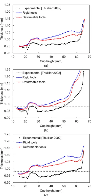
Thepunchspeedduringtheformingoperation(bothstages)is 3.3mm/s.Theaccuracyreachedinthemeasurementofthepunch displacementis±0.02mm,whiletheloadisrecordedwith0.4%of accuracy(Thuillieretal., 2010).Five formingtestsunderidentical process conditions were performed in order to check the repro-ducibility oftheobtainedexperimental data.After thefirst stage, some cylindrical cups are extracted for thickness measurement, whileothersare deformedinthereversedirection. Thethickness of the cup wall is measured using a three-dimensional coordi-natemeasuringmachine(DEASwiftA001).Threestraightlinesare marked onthe sheetbeforeforming (0º,45ºand90º) toperform the thickness measurement in three directions to the rolling di-rection,usingan incrementof 1mmbetweenconsecutive points. Furthermore,aholeistrimmedinthe bottomofthecuptofixit onthetableofthemeasuringmachine.Thepoint coordinatesare evaluatedonbothsidesofthecylindricalcups(insideandoutside) atthesameheight,allowingthedefinitionofahorizontaldistance measured intheradial direction(Thuillieretal.,2010),asshown inFig.6.
4.2. Finiteelementmodel
Thenumericalsimulations were carriedoutwiththein-house static implicitfinite element code DD3IMP (Menezes and Teodo-siu,2000),specificallydevelopedtosimulatesheetmetal forming processes(Oliveiraetal.,2008).Inordertoimprovethe computa-tionalperformance,somehigh-performancecomputingtechniques havebeenincorporatedtotakeadvantageofmulti-coreprocessors, namelyOpenMP directives inthe mosttime-consumingbranches ofthecode(Menezesetal.,2011).Allnumericalsimulationswere performedonacomputermachineequippedwithanIntel®CoreTM
i7–4770KQuad-Coreprocessor(3.5GHz)andtheWindows7 Pro-fessional(64-bitplatform)operatingsystem.
Fig.5. Schemes of the forming tools used in the reverse deep drawing of a cylindrical cup: (a) first stage; (b) second stage.
t
t t
Fig.6. Measurement of the wall thickness in the cylindrical cup.
Fig. 7. Discretization of the blank using 15,408 solid finite elements (2 layers through the thickness).
4.2.1. Blankmodelling
Duetogeometricandmaterialsymmetryconditions,only one-quarteroftheblankismodelled,whichisdiscretizedwith8-node hexahedralfiniteelements,associatedwithaselectivereduced in-tegrationtechnique(Hughes,1980).Usingsolidelementstomodel the blank it is possibleto evaluate accurately the gradients over the thickness, aswell asthecontactforces (Menezesand Teodo-siu,2000;Teodosiuetal., 1995).The totalnumberofelementsis 15,408(see Fig. 7),using 2layers ofelementsthrough the
thick-Table4
Number of Nagata patches used to de- scribe each rigid forming tool involved in the reverse deep drawing process.
Tool Stage 1 Stage 2
Die 180 260
Punch 260 210
Blank-holder 80 180
Total 520 650
ness.Thefrictionbetweentheblankandtheformingtoolis mod-elledthroughtheclassicalCoulomb’slaw.Thevalueofthefriction coefficient suggestedinthebenchmark specificationsis
μ
=0.15, whichisinaccordance withthe value measuredby Trzepieci´nski etal.(2015),usingthree differenttribologicaltests:stripdrawing test,drawbeadtestandpin-on-disctribometer,considering lubri-cationconditionsandsteady-stateregions.4.2.2. Rigidtools
Currently,themodellingoftheformingtoolsiscarriedoutwith rigidsurfaces,neglectingtheir elasticdeformation. Thus,only the outer surface ofthe forming tools is modelled, which is directly usedin thedefinition ofthe frictional contactconstraints.In the present study, the surface of the tools is described with Nagata patches (Netoet al.,2014b, 2013),providing an accurate geomet-ricaldescription(Netoetal.,2015a).Thediscretizationofthetools involved in the reverse deep drawing process (one-quarter due to symmetry conditions) is presented in Fig.8, for both forming stages.Inordertoobtainanegligibleshapeerror,eachcirculararc isdescribedby4Nagatapatchesintheradialdirectionwhileeach toolisdiscretizedwith20patchesinthecircumferentialdirection (see Fig.8). The totalnumber ofNagata patches composingeach formingtoolforbothstagesispresentedinTable4.Theclearance betweenthedieandtheblank-holderusedinthenumericalmodel is1.10mminthefirststage and1.4mminthesecondstage.Note that the clearance adopted in the numerical model for the first forming stage is slightly larger than the experimental value (see Section4.1).
Thecuprimresultingfromthefirstformingstageneedtopass betweenthedieandtheblank-holderduringthesecondstage,as shownin Fig. 5(b). Therefore, in order to avoid the convergence problemsrelatedtothecontactbetweenthecuprimandthesharp edge of the blank-holder, a fillet radius of 1.0mm is introduced in the free boundary of the vertical wall, asshown in Fig. 8(b). Thisstrategy overcomes the flip–flopeffect arising fromthe con-tactconstraintsenforcement,i.e.constantswitchingbetween
con-Die Punch Blank-holder Blank x y z Die Blank Punch Blank-holder
Fig.8. Discretization of the (rigid) forming tools using Nagata patches: (a) first stage; (b) second stage.
Fig.9. Discretization of the (deformable) forming tools using solid finite elements: (a) first stage; (b) second stage.
tactandgapstatuses(Netoetal.,2015).Anidenticalprocedureis adoptedinthemodelthatconsidersdeformabletools.
4.2.3. Deformabletools
Duetogeometricandmaterialsymmetryconditions,only one-quarteroftheformingtoolsismodelled.Theyarediscretizedwith solid finiteelements, allowing take into account its elastic defor-mation.Typically,thesurfacedetailsinvolved inthetoolsrequire afinemeshinthesezones,leadingtoasignificantincreaseinthe totalnumberoffiniteelements.Thisissuecanbeovercomeby ap-plying a surface smoothing method on the coarse mesh, provid-ing an accurate description of the curved surfaces usinga small amountof finite elements. Several surfacesmoothing procedures havebeenproposed in thelast decade (Neto etal., 2015). In the presentstudy,eachtoolsurfaceissmoothedwithNagatapatches, following the procedure proposed by Neto et al. (2016) for fric-tionalcontactproblemsbetweendeformablebodies.
The discretizationofeachforming toolinvolvedinthereverse deepdrawingprocess is presentedinFig. 9. Thediscretization of thedeformabletoolsinthecurvedsurfacesisidenticaltothe pre-viouslyused forrigidtools(compareFig. 8andFig.9), providing asimilarshapeerrorresultingfromthesurfaceinterpolationwith
Table5
Number of finite elements used to de- scribe each deformable forming tool involved in the reverse deep drawing process.
Tool Stage 1 Stage 2
Die 2480 2880
Punch 2880 3003
Blank-holder 480 1320
Total 5840 7203
Nagatapatches.Consequently,thegeometricalaccuracyofthetool surfacesisthesameforbothfiniteelementmodels.Thenumberof finiteelementsusedtodefineeachdeformableformingtoolis pre-sentedinTable5.Thegeometryofthetoolswassimplifiedinthe region ofthe screws (see Fig. 5), where adequate boundary con-ditions are appliedto representthe physical connectionbetween thedieandtheblank-holder.Sincethescrewsarelocatedona di-ameter of 185mm (see Section 4.1), the tools are modelled only withinthisperimeter,whichisfixedinalldirections,establishing an initialclearanceof1.0mmbetweenthem.Besides,thevertical
0 10 20 30 40 50 60 70 80 90 0 10 20 30 40 50 ] N k[ e cr of h c n u P Punch displacement [mm] Experimental [Thuillier 2002] Rigid tools (gap=1.10 mm) Deformable tools
Fig.10. Comparison between experimental and numerical punch force evolution during the first forming stage.
displacement imposedto thepunch is appliedon itstop surface. Accordingly,an identicalprocedureisadoptedforthetoolsofthe secondstage.
Themechanicalbehaviouroftheformingtoolsisassumed elas-tic and isotropic (von Mises). Since the tools are made of steel, their elastic properties are identical to the ones adopted forthe blank, i.e.Young’s modulus of 210GPa andPoisson ratioof 0.30. Nevertheless, their yield strength is significantly higher, about 400MPa.
4.3. Resultsanddiscussion
The comparison between different numerical approaches to model the forming tools is presented. Furthermore, the numeri-cal resultsare comparedwiththeexperimental onesprovided by Thuillieretal.(2002),highlightingtheinfluenceofthetools mod-ellingintheaccuracyofthefiniteelementsolution.
4.3.1. Formingforces
The comparison between experimental and numerical punch force evolution is shown in Fig. 10, for the first forming stage. Globally,theexperimentalpunchforceisoverestimatedbythe nu-merical model that takes intoaccount theelastic deformation of thetools,whileitis underestimatedwhenconsidering rigidtools inthefiniteelement model.Nevertheless,note thattheclearance between the die and the blank-holder adopted in the finite ele-ment modelusingrigidtools(1.10mm)ishigherthan the exper-imental value (1.0mm). Sincethe deformation modeofthe sheet isclosetouniaxial compressionintheflange (Netoetal.,2014a), the increase ofthe sheetthickness inthis regionleads toan in-creaseofpunchforceduetothelargerestrainingforces.Therefore, theclearancebetweenthedieandtheblank-holderwasenlarged toavoidtheironingoftheflangeinthefiniteelementsimulation. However,theadoptedvalueofclearance(1.10mm)isnotsufficient tocompletelyeliminatetheironingeffect,whichishighlightedby theabruptincreaseofthepunch forceatapproximately35mmof punch displacement (see Fig. 10). Onthe other hand, the punch forceevolutionprovidedbythenumericalmodelusingdeformable tools(1.0mmofinitialgap)isinbetteragreementwiththe experi-mentalone,asshowninFig.10.Thesuddendecreaseofthepunch force ataround43mmofdisplacementoccursforbothnumerical models(rigidanddeformabletools),whichisrelatedtothelossof contactbetweenthesheetandtheblank-holder.Thepossible mis-alignmentofthesheetwiththeformingtoolsintheexperimental
proceduremayexplainthesmootherdecreaseoftheexperimental punchforce.
Although the mesh adopted in the discretization of the de-formableformingtools(Fig.9)canbe consideredcoarse,the evo-lutionof the punch force is smooth (see Fig. 10). Thisis related withtheappliedsurfacesmoothingprocedure (Netoetal., 2016), whicheliminatesthenonphysicaloscillations inthecontactforce induced by the discontinuity of the surface normal vector field. The nodal contactforces arising in the slave nodes belonging to thesymmetry plane are presented inFig.11,for theinstant cor-responding to 25mm ofpunch displacement. The contactoccurs mainlyinthecurvedzonesoftheformingtools,whereitis possi-bletoseethat thesurfacesmoothingmethodiseffective.Infact, thecontact forcesare properly distributed onthe smoothed sur-face,despite the apparent gapbetweenthe punch and thesheet (seeFig.11(a))andbetweenthedieandthesheet(seeFig.11(b)), inthecurvedcontactzones.
Concerningthesecondformingstage,Fig.12presentsthe com-parison betweenexperimental andnumerical punch force evolu-tion.Thenumericalresultsaresimilarforbothfiniteelement mod-els(rigidanddeformabletools),indicatingthatthetools deforma-tionis negligiblein thesecond stage. The numericalpunch force evolution is in very good agreement with the experimental one duringthe initial 35mm of punch displacement. In fact, the ini-tialslopepredictedbythenumericalsimulationiscoincidentwith theexperimental one.Ontheotherhand,theexperimentalpunch force exhibits a peak for a punch stroke around 40mm, which is underestimated by the numericalsimulation, both in terms of valueandtheinstantofoccurrence,asshowninFig.12.Sincethe cylindricalcup isnotcompletelyformed,thispeakoftheforce is associatedwith thepassage ofthe cuprim betweenthe dieand theblank-holder(seeFig.9(b)).Thedifference betweennumerical andexperimental force peakis connectedwiththe final value of the punch force in thefirst forming stage (see Fig. 10), which is underestimatedbythenumericalsimulation.Thus,theslight mis-alignmentofthesheetwiththeformingtoolsintheexperimental setup can lead to an increase ofthe restraining forces arising in thecuprim.
The evolution of the blank-holder force as a function of the punch displacement is presented in Fig. 13, for both forming stages,comparing the two numerical models developed. Regard-ing the first stage, the force value predicted by the model that takes into account the tools deformation is globallyhigher than theoneobtainedconsideringrigidtools.Notethatthefixed clear-ance betweenthedie andthe blank-holderislarger inthe finite elementmodelusingrigidtools(1.10mm). Theabruptincreaseof theblank-holderforceatapproximately35mmofpunch displace-ment (see Fig. 13) is a consequence of the ironing effect in the flange,whichonlyoccurswhenusingrigidtoolsinthefinite ele-mentmodel.The magnitudeofthe blank-holderforce duringthe secondformingstageisconsiderablylowerthaninthefirststage, asshowninFig.13,since theclearancebetweenthe dieandthe blank-holderis larger (see Section 2). Moreover,the small differ-encebetweenthetwofiniteelementmodelsintermsofpredicted forcesindicatesan insignificantdeflectionofthetoolsinthe sec-ondstage.
4.3.2. Toolsdeflection
Thedeflectionofthetoolsduringthefirstformingstageis as-sessedinthepresentstudythroughthenodaldisplacements eval-uatedinthetools,specificallytheblank-holderandthedie.Fig.14 presents the evolution of the vertical displacement of six nodes (three positioned in the blank-holder and three in the die) as a functionofthepunch displacement.Thedeformation ofthetools comesup fromthethickening oftheflange, whichis inducedby thecircumferential compressivestress state(uniaxialcompressive
Fig.11. Nodal contact forces in the slave nodes for 25 mm of punch displacement (magnitude denoted by arrow size and colour): (a) contact between sheet and punch; (b) contact between sheet and die as well as between sheet and blank-holder.
0 10 20 30 40 50 60 70 80 0 10 20 30 40 50 60 70 ] N k[ e cr of h c n u P Punch displacement [mm] Experimental [Thuillier 2002] Rigid tools Deformable tools
Fig.12. Comparison between experimental and numerical punch force evolution during the second forming stage.
0 10 20 30 40 50 60 70 80 90 100 0 10 20 30 40 50 60 70 k n al B -] N k[ e cr of r e dl o h Punch displacement [mm] Rigid tools (stage 1)
Rigid tools (stage 2) Def. tools (stage 1) Def. tools (stage 2)
Fig.13. Evolution of the predicted blank-holder force as a function of the punch displacement for both forming stages, comparing rigid and deformable forming tools.
strain).Inordertoquantifytheinfluenceoftheplasticanisotropy ofthe sheet(see Fig. 2) in the elastic deformation of the form-ing tools,the selected nodes are positioned along the circumfer-entialdirection, namelyintherolling direction(RD),diagonal di-rection(DD) andtransverse direction(TD).The nodes 1,2and 3 arelocatedintheopendiameteroftheblank-holder(contact sur-face), while the nodes 4, 5 and 6 are located in the die radius
Fig.14. Vertical displacement of three nodes (node 1, 2 and 3) located in the open diameter of the blank-holder and three nodes (node 4, 5 and 6) located in the die radius (first forming stage).
Fig.15. Contour plot of the nodal displacements (mm) in the die and blank-holder for 25 mm of punch displacement.
(transitionwithhorizontalcontactsurface).Adoptingthefinite ele-mentmodelwithdeformabletools,theeffectiveclearancebetween the die andthe blank-holder increases gradually and then drops quicklytotheinitial valuewhenthe sheetloses contactwiththe blank-holder,asshowninFig.14.Themaximumvalueofclearance achieved(about1.11mm)occursfor40mmofpunchdisplacement, whichistheinstantwhereironingoftheflangeoccursusingrigid tools(seeFig.10).Hence,theclearanceof1.10mmadoptedinthe modelwithrigidtoolsisinsufficienttoaccommodatetheincrease in thickness. Since the die is roughly 3 times thicker than the blank-holder (Fig. 9(a)), the nodalvertical displacements are sig-nificantlylargerintheblank-holder,ashighlightedinFig.14.
The contour plot of the nodal displacements in the die and blank-holderispresentedinFig.15,fortheinstant corresponding to25mmofpunchdisplacement.Duetotheboundaryconditions applied in the outer perimeter of the die and blank-holder, the nodal displacements are zero in thisregion. The largest value of
1 1.01 1.02 1.03 1.04 1.05 1.06 1.07 50 55 60 65 70 75 80 85 90 ] m m[ et a ni dr o o c z Radial coordinate [mm] RD DD TD
Fig.16. Profile of the blank-holder surface (first forming stage) measured in three directions, for 25 mm of punch displacement.
Fig. 17. von Mises stress distribution (MPa) in the forming tools for 25 mm of punch displacement.
displacement occursintheblank-holderopeningdiameter,which is predominantlyinthe verticaldirection. Onthe other hand,for the same radial distance, the deflection of the die is at least 5 times lower than the one ofblank-holder. Indeed, themaximum valueofthenodaldisplacementsisinferiorto0.014mminthedie (seeFig.15).
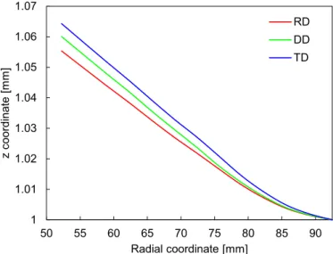
Thedeformedconfigurationoftheblank-holderinvolvedinthe first forming stage is presented in Fig. 16, for the instant corre-sponding to 25mm of punch displacement. In order to analyse the influence of the sheetanisotropy in the blank-holder deflec-tion,threedifferentcrosssectionsareassessed,namelyintheRD, DD andTD. Theprofile ofthe deformedblank-holderisdifferent foreachanalysedcrosssection(seeFig.16),becausethepredicted thicknessdistributionisnon-uniforminthecircumferential direc-tion andthe draw-inis asymmetric.Indeed, thethickness ofthe flangeanditsdraw-inaredirectlyconnectedthroughthe assump-tionoftheincompressibilitycondition(Netoetal.,2014a), present-ing opposite effects on the blank-holder deflection. Accordingly, theclearancebetweenthedieandtheblank-holderislargerinthe TDandsmallerintheRD,asshowninFig.16.However, the rela-tivetrendbetweenthethreesectionspresentschangesduringthe formingprocessevolution,specificallyintheDD(seeFig.14).
The von Misesstress distributioninthe formingtools (punch, blank-holder anddie) ispresented inFig. 17, forthe instant cor-respondingto25mmofpunchdisplacement.Themaximumvalue ofthestressarisesclosetotheperimeteroftheblank-holderdue totheappliedboundaryconditions(prescribeddisplacements)and small stiffness of the blank-holder in comparison with the die. Sincethemaximumvalueofequivalentstresspredictedbythe nu-mericalsimulationisabout112MPa,theformingtoolsonlyexhibit
Rigid tools
Deformable tools
RD
Fig.18. Equivalent plastic strain distribution plotted in the deformed configuration of the cylindrical cup after the first forming stage. Finite element model using rigid tools (left) and using deformable tools (right).
Fig.19. Experimental geometry of the cylindrical cup obtained by reverse deep drawing: (a) first stage; (b) second stage.
elasticdeformationduringthecupforming.Additionally,thestress distributionisasymmetricinthe tools(Fig.17),whichisinduced bytheplasticanisotropyofthesheet.Nevertheless,thestress dis-tributioninthepunch islessinfluenced bytheplasticanisotropy ofthesheet,since thecontactzoneisalmost insensitivetosheet thicknessvariations.
4.3.3. Cupgeometry
The significant deflection of the blank-holder during the first formingstageaffectsthematerialflow,asthedistributionof con-tactpressureontheflange isdifferentfromtheone obtained us-ing rigidtools(Shulkinetal., 1996). The equivalentplasticstrain distributionpredictedbyfiniteelementsimulationispresentedin Fig.18, at the endof the first formingstage, comparing the nu-mericalmodelsanalysed(rigidanddeformabletools).Althoughthe elasticdeformationofthe blank-holderis non-negligible(Fig.15), thefinal configurationofthe cylindricalcup is identicalforboth numericalmodels.Sincethepunchforce isnonzeroattheendof thefirst stage (seeFig. 10),the cupis not fullydrawn,asshown intheexperimentalgeometryofthecupafterthefirststage pre-sented in Fig. 19(a). The maximum value of plastic strain pre-dictedbythenumericalmodelisreachedinthecuprim.Thevalue of equivalentplastic strain is lower in the DD for the same cup height,whichisinaccordancewiththeearingprofile(fourears).
The final configurationof the cylindricalcup afterthe second forming stage is presented in Fig. 20, comparing the two finite element models proposed in Section 3. The main difference oc-curs in the DD, where the numerical model that takes into ac-counttheelasticdeformationoftheformingtoolspredictsthe oc-currenceofwrinkling.Thelargecircumferentialcompressivestress andtheearingeffectinducedby theplasticanisotropy yields the