Separation Logic for High-Level Synthesis
Felix Winterstein
14th April 2016
Supervised by George A. Constantinides
Submitted in part fulfilment of the requirements for the degree of
Doctor of Philosophy in Electrical and Electronic Engineering of Imperial College London and the Diploma of Imperial College London
searchers are free to copy, distribute or transmit the thesis on the condition that they attribute it, that they do not use it for commercial purposes and that they do not alter, transform or build upon it. For any reuse or redistribution, researchers must make clear to others the licence terms of this work.
High-level synthesis (HLS) promises a significant shortening of the digital hardware de-sign cycle by raising the abstraction level of the dede-sign entry to high-level languages such as C/C++. However, applications using dynamic, pointer-based data structures remain
difficult to implement well, yet such constructs are widely used in software. Automated
optimisations that leverage the memory bandwidth of dedicated hardware implementa-tions by distributing the application data over separate on-chip memories and parallelise the implementation are often ine↵ective in the presence of dynamic data structures, due
to the lack of an automated analysis that disambiguates pointer-based memory accesses. This thesis takes a step towards closing this gap. We explore recent advances inseparation logic, a rigorous mathematical framework that enables formal reasoning about the memory access of heap-manipulating programs. We develop a static analysis that automatically splits heap-allocated data structures into provably disjoint regions. Our algorithm fo-cuses on dynamic data structures accessed in loops and is accompanied by automated source-to-source transformations which enable loop parallelisation and physical memory partitioning by o↵-the-shelf HLS tools.
We then extend the scope of our technique to pointer-based memory-intensive implemen-tations that require access to an o↵-chip memory. The extended HLS design aid generates
parallel on-chip multi-cache architectures. It uses the disjointness property of memory accesses to support non-overlapping memory regions by private caches. It also identifies regions which are shared after parallelisation and which are supported by parallel caches with a coherency mechanism and synchronisation, resulting in automatically specialised memory systems. We show up to 15⇥acceleration from heap partitioning, parallelisation and the insertion of the custom cache system in demonstrably practical applications.
I would like to thank my PhD advisor Prof. George Constantinides for his encouragement, his excellent support and for sparking my interest in separation logic. George has given me the freedom to pursue my own research questions and helped guide my thoughts with sage advice, sharp insight and inspiring ideas. It is largely due to the research environment he has created that this work resulted in a thesis of which I am proud.
I thank my colleagues at Imperial, especially Shane Fleming, Andrea Suardi, John Wick-erson, Samuel Bayliss, Michalis Vavouras, Grigorios Mingas, Nadesh Ramanathan, David Boland and Ivan Beretta who have made the Circuits and Systems Group an inspiring and vibrant work environment. Special thanks go to Shane and his wife Iza who have become close friends and regularly hosted me during the many short visits to London.
I also thank the European Space Agency for funding my research and my former colleagues from ESA’s Ground Station Systems Division for being such pleasant company. In par-ticular, I would like to thank Gunther Sessler for being an excellent mentor and a friend. In addition to him, it was with the help of Marco Lanucara and Piermario Besso that my application for ESA’s contribution to my PhD funding was successful.
Outside of Imperial and ESA, I would like to thank Hsin-Jung Yang from MIT and Elliott Fleming from Intel for a very productive collaboration during the last two years.
I am grateful for the advice and support given by my parents Sabine and Bernhard Win-terstein and my brother Florian.
Finally, I thank my wonderful partner Stephanie for her love, patience and support. You made this thesis possible.
1. Introduction 16
1.1. Research Contributions . . . 22
1.2. Thesis Outline . . . 23
1.3. Statement of Originality . . . 24
2. High-level Synthesis of Dynamic Data Structures 27 2.1. Background . . . 30
2.2. Analysis of the Filtering Algorithm . . . 35
2.3. RTL Implementations . . . 37 2.3.1. Lloyd’s Algorithm . . . 38 2.3.2. Filtering Algorithm . . . 38 2.4. HLS Implementations . . . 42 2.4.1. Lloyd’s Algorithm . . . 43 2.4.2. Filtering Algorithm . . . 43 2.5. Performance Comparison . . . 46 2.5.1. RTL Designs . . . 47 2.5.2. HLS Designs . . . 49 2.6. Summary . . . 51 3. Background 54 3.1. Profiling and User Annotation-Based Approaches . . . 55
3.2. Automated Static Analyses for Static Control Parts . . . 58
3.4. HLS Support for Pointers and Dynamic Memory Allocation . . . 63
3.5. Static Analysis Based on Separation Logic . . . 66
3.5.1. Modelling Program State in Separation Logic . . . 67
3.5.2. Programming Language . . . 70
3.5.3. Symbolic Execution of Programs . . . 71
3.5.4. Theorem Proving . . . 74
3.5.5. Application to HLS . . . 77
4. Heap Partitioning and Parallelisation 79 4.1. Motivating Example . . . 81
4.2. Program Analysis . . . 85
4.2.1. Inserting Cut-points . . . 87
4.2.2. Proving Communication-free Parallelism . . . 89
4.2.3. Assigning Heap Partition Information to Statements . . . 91
4.3. Implementation . . . 93
4.3.1. Heap Analyser . . . 95
4.3.2. Memory Access . . . 97
4.3.3. Dynamic Memory Allocation . . . 97
4.3.4. Control and Data Flow . . . 98
4.3.5. Source-to-Source Compiler . . . 100
4.4. Experiments . . . 102
4.5. Performance and Robustness of the Heap Analysis . . . 107
4.6. Summary . . . 110
5. Custom Multi-Cache Architectures 112 5.1. Motivating Example . . . 114
5.1.1. Memory Partitioning and Parallelisation . . . 115
5.1.2. Parallel Access to Shared Resources . . . 118
5.2. Extended Static Program Analysis . . . 120
5.2.1. Detecting Private and Shared Resources . . . 122
5.2.2. Commutativity Analysis . . . 123
5.3. Code Generation . . . 126
5.4. Custom Cache Sizing . . . 129
5.4.1. On-chip Memory Utilisation Estimation . . . 132
5.4.2. Cache Performance Estimation . . . 133
5.4.3. Optimisation Strategy . . . 136
5.5. Experiments . . . 137
5.5.1. Hybrid Multi-Cache Architectures . . . 138
5.5.2. Validating the BRAM Estimation for Automated Cache Scaling . . . 141
5.5.3. Validating Cache Performance Estimation . . . 143
5.5.4. Latency and Resource Utilisation after Custom Cache Scaling . . . . 143
5.5.5. Energy Consumption . . . 146 5.6. Summary . . . 148 6. Conclusion 150 6.1. Outlook . . . 154 6.2. Final Remarks . . . 157 Bibliography 158 Appendices 173 A. Context-Aware Heap Analysis 173 A.1. Overlaid Sub-Analyses . . . 176
2.1. Computational complexity of the filtering algorithm broken down into
clus-tering and pre-processing phases. . . 36
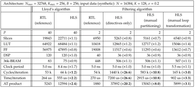
2.2. Resource comparison for a 270µs-latency constraint (input parameters:N= 16384,K=128, =0.2). . . 49
2.3. Performance comparison using the hand-written RTL designs as reference. 50 4.1. Implementation results and comparison. . . 104
4.2. Comparison with hand-written HLS/RTL designs. . . 105
4.3. Tool execution time. . . 106
5.1. Parallelisation and caching (cache size 1 kB). . . 139
5.2. Cost increase of all-coherent default compared to application-specific hybrid scratchpad architectures. . . 141
5.3. High-level BRAM estimation accuracy (results in 36k-RAM blocks). . . 142
5.4. Cache hit/miss count estimation for two private caches inReflect tree. . . . 143
5.5. Latency and resource utilisation after custom cache scaling. . . 145
2.1. Design flow of the case study . . . 29 2.2. Left: Frequency of candidate centre set sizes for synthetic input data. Right:
Computational complexity of the filtering algorithm in terms of node-centre pairs (Lloyd’s algorithm has a constant complexity of 209.7⇥104point-centre
pairs for this data set). . . 37 2.3. Left: FPGA implementation of the filtering algorithm. Right: Read-write
accesses to the scratchpad memory for centre sets during tree traversal. . . . 39 2.4. Trade-o↵between heap size and run-time of the filtering algorithm (profiling). 42
2.5. Left: Average cycle count per iteration for the manual RTL implementation of the filtering algorithm (P=1). Right: Speed-up over an RTL
implemen-tation of Lloyd’s algorithm (P=1 in both cases). . . 47
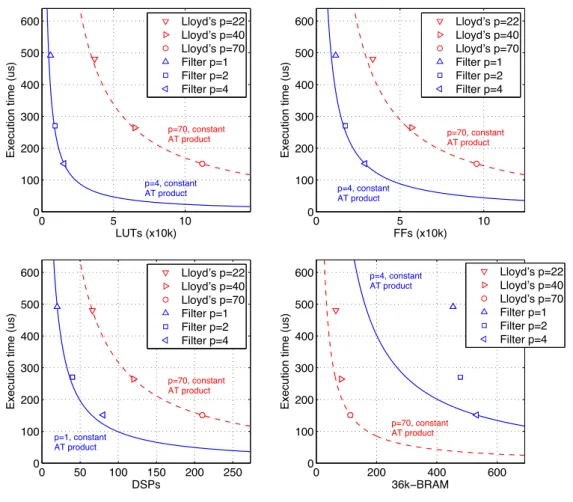
2.6. Mean execution time per iteration over FPGA resources for N = 16384,
K=128, =0.2 (Xilinx Virtex7 7vx485t↵g-2). . . 48
4.1. High-level compilation tool flow. . . 80 4.2. Snapshot of the linked data structures accessed by the loop in Listing 4.1. . 83 4.3. Synthesised hardware from the transformed code in Listing 4.2. . . 84 4.4. Pre-state before execution of the first (left) and the second loop iteration (right). 87 4.5. LLVM-based CAD flow including the heap analyser, source translator and
third party tools for HLS and RTL implementation. . . 95 4.6. Analysis complexity for Filter. Left: number of disjunctive clauses (total
and removed). Right: tool execution time per fix-point iteration. . . 107 4.7. Punctured linked list. . . 108
5.1. Summary of the extended tool flow presented in this chapter. . . 113 5.2. Snapshot of the pointer-linked dynamic data structures accessed by the loop
in Listing 5.1. . . 117 5.3. Parallelised HLS implementation of the filtering algorithm with a hybrid
cache architecture. . . 127 5.4. Aggregate hit rate estimate for a two-cache system with an 2200 kB on-chip
memory constraint. . . 131 A.1. Heap layout and pointer assignment during the first four iterations of the
loop in Listing A. . . 175 A.2. Program state described by the two sub-analyses Land Cin (A.4). . . 178
AC All-Coherent.
ASIC Application-Specific Integrated Circuit.
ASIP Application-Specific Instruction Set Processor.
AT Area-Time.
BRAM Block Random Access Memory.
CAD Computer Aided Design.
CFG Control Flow Graph.
CI Centroid Information.
CPU Central Processing Unit.
CS Centre Sets.
DCE Distance Computation Equivalent.
DEF-USE Definition-Usage.
DRAM Dynamic Random Access Memory.
DSP Digital Signal Processing.
FF Flip-Flop.
FIFO First-In First Out.
FPGA Field-Programmable Gate Array.
GPU Graphics Processing Unit.
HDL Hardware Description Language.
HLS High-Level Synthesis.
HY Hybrid.
ILP Integer Linear Programming.
IR Intermediate Representation.
LEAP Latency-Insensitive Environment for Application Programming.
LLVM Low-Level Virtual Machine.
LLVM IR LLVM Intermediate Representation.
LUT Look-up Table.
MIT Massachusetts Institute of Technology.
PAR Placement-And-Routing.
QoR Quality of Results.
RAM Random Access Memory.
RTL Register Transfer Level.
SD Stack Distance.
SDRAM Synchronous Dynamic Random Access Memory.
SP Scratchpad.
SSA Single Static Assignment.
ST Stack Records.
With the increasing demand for performance and efficiency of computing devices, cus-tom computing is a growing area in digital computation today, which represents a class of processing devices that are dedicated to an application or a range of similar appli-cations. Custom computing devices can achieve higher energy or power efficiency and
performance with respect to general-purpose microprocessors, which can execute any task on the same underlying hardware [1, 2, 3, 4, 5, 6, 7, 8]. Efficiency and performance are
gained by avoiding unnecessary circuitry for a specific computing task, and the design of custom data paths and memory systems. The trade-o↵between flexibility and
perfor-mance/efficiency varies across di↵erent classes of specialised computing machines: Digital
signal processors and application-specific instruction set processors (ASIPs) are software-programmable and provide extended hardware support for domain-specific features. On the other hand, digital application-specific integrated circuits (ASICs) are fully customised processors that implement computation based on a digital circuit which is usually dedi-cated to a single application; once produced, the functionality of an ASIC is hard-wired and cannot be changed. Field-programmable gate arrays (FPGAs) have a particular role in the flexibility/performance trade-o↵in that they combine programmability with an efficient
dedicated circuit implementation for a particular application. An FPGA consists of con-figurable logic cells and interconnects and typically can be reprogrammed to implement di↵erent computing tasks post-fabrication.
The traditional design entries of ASIC and FPGA implementations are largely similar in the first phases of the design flow. A hardware model is written in a hardware
descrip-tion language (HDL) such as VHDL [9] or Verilog [10] at the level of abstracdescrip-tion referred to as register transfer level (RTL). The specification at RTL allows the user to have full control over the low-level details of the data path and memory system implementations on the chip and to navigate the implementation through a large design space. However, producing a manual RTL specification requires significant design and verification e↵ort,
including several iterations of design optimisation and verification phases. The develop-ment times for complex ASIC impledevelop-mentations may amount to several years until tape-out, while RTL design and verification dominate the overall development cycle. The design cycle for FPGA implementations is typically shorter, but the design e↵ort at RTL is
sim-ilar. Long implementation cycles are a hindrance for an adoption of FPGAs as efficient
yet flexible processing devices: reprogrammability encourages their use in a similar way as microprocessors are used in that the same hardware can execute di↵erent ‘programs’.
However, prohibitively long development times compared to software implementations fundamentally limit this versatility. Furthermore, the RTL design entry inevitably requires familiarity with the low-level details of digital hardware design. The conceptual di↵
er-ence between the application development for FPGAs and for instruction set architectures hinders the wide adoption of FPGA technology by software developers and application engineers without experience in circuit design [11].
The low productivity of application development at RTL has encouraged the electronic design automation (EDA) community to raise the abstraction level of application descrip-tions from RTL to high-level languages such as C/C++. High-level synthesis (HLS) tools
take these descriptions as input and automatically generate RTL specifications which can be synthesised and mapped into hardware by standard back-end RTL tool flows. High-level design entry can significantly shorten the development cycle when compared with RTL-based specification. Remarkable e↵ort in academia and industry has led to various
HLS tools targeting ASIC and FPGA technology. With C/C++being one of the most
preva-lent programming languages used to date and with large bases of legacy codes written in it, RTL compilation from C/C++and derivatives thereof has a long-standing tradition in
industrial [12, 13, 14, 15, 16, 17, 18, 19, 20, 21] and academic [22, 23, 24, 25, 26] development. The admissible source code entry to these tools is restricted to synthesisable subsets of the C language.
HLS has experienced an increased interest in the last decade, which we believe is due to two main reasons. Firstly, state-of-the-art tools have increased performance compared to previous generations of tools developed in the mid 1990s [27]. The performance of an HLS tool can be measured in the quality of results (QoR) of the resulting RTL description in terms of execution time and hardware resource utilisation. Recent evaluations [28, 29, 30] show that state-of-the-art tools, such as Xilinx Vivado HLS [19], can achieve a QoR com-parable to hand-written HDL code. Secondly, technology scaling has brought the number of transistors on a chip to point where the RTL design e↵ort required to make efficient use
this resource is becoming an increasingly severe limitation [11]. On the other hand, the abundance of hardware resources makes the trade-o↵between the QoR of hand-written
HDL and generated HLS designs and design times appealing to more and more users, a fact that is especially true for FPGA implementations whose end-to-end development time is usually significantly shorter than that of ASIC designs [31, 11].
Despite the encouraging QoR results of FPGA-targeted HLS evaluations for particular benchmarks [28, 29, 32, 31, 30], there are types of programs that either cannot be syn-thesised at all, or result in a poor QoR. Applications using dynamic, pointer-based data structures and dynamic memory allocation are examples of such programs. The objective of this thesis is to extend the scope of current HLS to suchpointer-based programs. Our work is motivated by the fact that pointer-based memory references and dynamic memory allocation are well established and widely used features of high-level languages such as C++. However, their analysis and automated program optimisations resulting from it are
beyond the scope of the overwhelming majority of HLS techniques to date. Although dynamic memory allocation, an unsupported feature in common HLS flows, can be made synthesisable with manual source code modifications, pointer-based programs often do
not result in efficient hardware implementations. As we shall see in Chapter 2, the HLS
implementation of such a program can be degraded by a factor larger than 26⇥in terms of execution time compared to a hand-crafted RTL design if the source code is not further optimised prior to HLS. The reward for extensive manual code optimisations is shown to be an 8⇥improvement of the execution time.
We identify two aspects that are crucial for improving the QoR. The first is the extraction of parallelism from a pointer-based application while preserving the program semantics, which is usually based on a dependence analysis. Secondly, computational parallelism requires that the memory system is not a sequential bottleneck to performance. We aim to make efficient use of the customisable memory architecture in FPGAs, which is a key
fea-ture distinguishing FPGAs from microprocessors. Instead of a monolithic memory space, the application data can be distributed over many small blocks of on-chip memory leading to a high aggregate memory bandwidth. Consequently, multiple computational units can be fed in parallel which results in a very efficient parallelisation if expensive dynamic
interconnects between any memory and any worker in a parallel computational unit can be reduced to single peer-to-peer connections,i.e. the parallelism is communication-free. The C model, however, assumes the presence of aheap, a large monolithic memory space in which a program allocates and frees up portions at run time. The difficulty of
parallelisa-tion and memory partiparallelisa-tioning lies in the disambiguaparallelisa-tion of memory references: regardless of scope, every two heap-directed pointers potentially alias,i.e. reference the same mem-ory cell, which leads to dependencies between expressions that are syntactically unrelated. The difficulty of analysing these programs is exacerbated by linked data structures which
contain pointers in their link fields.
Expanding on the encouraging results in Chapter 2, the scope of this thesis is to auto-mate source code transformations that enable parallelisation and memory partitioning in HLS flows. We present a static program analysis which breaks the monolithic heap mem-ory into several disjoint portions, which we refer to asheapletsin this thesis, and rules out
dependencies between code fragments that a standard HLS tool must assume potentially exist. The dependence/disjointness analysis enables automated source-to-source
transfor-mations for parallelisation and data distribution which can be exploited by a back-end HLS tool. Our departure point from previous work is the use of recent advances in sep-aration logic[33], a mathematical framework that allows a rigorous formal description of the program state and reasoning about the resources accessed by a program. Separation logic extends the classical propositional logic by an operator that explicitly expresses the separation of resources,i.e. the non-aliasing property of two pointers. This paves the way for an automated program analysis and can straightforwardly handle dynamic memory allocation in disjoint heaplets. Separation logic has predominantly been leveraged in mod-ern software verification tools. To the best of our knowledge, its application in the context of automated code optimisations for HLS remains largely unexplored. Experiments in Chapter 4, comparing the automatically parallelised to the direct HLS implementations, show an average reduction of execution time by a factor of 2.4⇥across several benchmarks.
Besides the on-chip memory partitioning and parallelisation, our source-to-source trans-formations ensure the synthesisability of heap-manipulating programs including dynamic memory allocation by standard HLS tools. The implementations in Chapter 4 are con-structed under the assumption that the application data fits in the physical on-chip mem-ory. However, the chances of exhausting the memory resources in an FPGA application with a large memory footprint are high since the maximum capacity of on-chip memory in state-of-the-art FPGAs is only in the order of tens of megabytes. We remove the limitation of being restricted to on-chip memory implementations in Chapter 5 by embedding HLS kernels in a framework that provides access to an external memory hierarchy consisting of board-level dynamic random access memory (DRAM) and host machine-level main memory. Accessing external memory, however, can substantially slow down the FPGA accelerator due to memory bandwidth limitations and, in the worst case, the contention on the external memory bus eliminates the gain of parallelisation. The starting point for our work in Chapter 5 is the insertion of on-chip caches to bu↵er frequently reused data
and to reduce the number of expensive accesses to the external memory.
Our main contribution in Chapter 5 is the application of an extended version of the base-line analysis in Chapter 4 to the automatic generation of an application-specific on-chip multi-cache architecture. Firstly, we extend the analysis such that, at compile time, it pro-vides precise information about which regions in heap memory will be shared after the implementation has been parallelised. This extends its scope to programs whose memory access pattern does not allow a partitioning into fully independent computational units and therefore broadens the applicability of our technique. Secondly, we use the disjoint-ness/sharing information to instantiate an application-specific, hybrid multi-cache system
that containsprivatecaches for heap regions known to be private for a computational unit and caches with an additional (and inherently more expensive)coherence mechanismand synchronisation service for shared heap regions. In the remainder of this thesis, we distin-guish between these two modes by referring toprivateandcoherentcaches, while the latter case corresponds to inter-cache coherency. We also extend the multi-cache construction with a technique for custom sizing so as to maximise the aggregate hit rate in private caches under a memory resource constraint. We demonstrate a speed-up of up to 15.2⇥after par-allelisation and generation of a multi-cache architecture compared to the unparallelised application and uncached access to the o↵-chip memory. Furthermore, the hybrid system
outperforms a default all-coherent version by 69.3% on average in terms of the area-time product across our benchmarks.
This thesis moves us towards the goal of supporting full-featured C/C++code in future
HLS flows by providing a framework that enables efficient FPGA acceleration of irregular
computation over pointer-based data structures. In Section 4.3, we propose an approach to integrate this framework into future HLS tools. The overall vision is that ‘standard’ soft-ware codes, including those from legacy code bases which have not been developed with HLS in mind, can be equally seamlessly mapped to FPGA accelerators while leaving the platform-specific optimisations to the compiler. This further raises the level of abstraction
in digital hardware design and may lead to a wider adoption of FPGA technology in an extended scope of applications.
1.1. Research Contributions
This thesis makes the following main contributions:
• A separation logic-based parallelisation algorithm for pointer-based programs which access dynamic data structures. Our static program analysis handles straight-line code as well as arbitrarywhile-loops and determines whether communication-free parallelism can be exposed in the loop execution with respect to the accessed dynamic data structures. Starting from the C memory model of a global monolithic heap memory, it determines how to partition the heap and dynamic data structures into disjoint partitions that can be implemented in separate on-chip memory blocks. • The implementation of an automated source-to-source transformation infrastructure:
The source translator ensures synthesisability of code containing unsupported con-structs related to dynamic memory allocation. In a second pass, the disjointness information provided by our analysis is used to split the synthesised heap memory into separate blocks and to split a loop into multiple loops so as to obtain a se-mantically equivalent parallel implementation. The property of communication-free parallelism ensures that each functional unit only requires access to its own private memory block.
• In addition to the identification of disjoint heap regions, we extend the baseline heap analysis by an identification of heaplets that would be shared by the parallel loop ker-nels after parallelisation. Our analysis inserts additional synchronisation primitives for program fragments that access shared resources. Even if coherency is ensured, updates to the shared resource may happen in a di↵erent order after
parallelisa-tion compared to the sequential program. We present acommutativity analysisfor the shared heap update in order to prove that the parallelisation is semantics-preserving.
• The extended framework targets FPGA accelerators with access to an o↵-chip
mem-ory. The disjointness and sharing information provided by our analyses are used to break the heap (residing in o↵-chip memory by default) into heaplets, to generate an
application-specific parallel multi-scratchpad architecture containing on-chip caches and (if needed) coherency mechanisms: we synthesise parallel private scratchpads for disjoint heap regions and (inherently more expensive) coherent parallel scratch-pads for shared regions.
• We further extend this framework by automated size scaling of private on-chip caches that uses spare on-chip memory resources. We generate individual sizing information for the multi-cache system and find the best size distribution for a user-provided memory access pattern of a particular application.
1.2. Thesis Outline
Before discussing the background and related work on program analyses, parallelisation and memory system optimisations in an HLS context in Chapter 3, this thesis begins with the presentation of a case study in the next chapter. The case study compares RTL and HLS implementations of two alternative algorithms for the same compute-intensive machine learning application (clustering) with significantly di↵erent computational properties: a
data-flow centric implementation and a recursive tree traversal implementation that incor-porates data-dependent control flow and makes use of pointer-linked data structures and dynamic memory allocation. The reason for this order of Chapters 2 and 3 is two-fold: 1) It introduces the type of problems this work addresses and provides a motivating example for mapping an efficient pointer-based algorithm to an FPGA rather than its pointer-less
brute-force counterpart. 2) It shows the capabilities and limitations of an exemplary state-of-the-art C-to-FPGA tool when synthesising pointer-based programs and proposes a set of manual source code alterations that result in a significantly more efficient HLS design.
framework that provides the foundation of our program analyses in Chapter 4 and 5. The analysis in Chapter 4 automates an important part of the code transformations of Chapter 2 that enables memory partitioning and parallelisation. Chapter 5 extends the scope of this work to the construction of multi-cache systems and shared memory accesses. Chapter 6 concludes this thesis and summarises the key ideas and concepts developed in this work. It also outlines directions of future research that build on the research contributions made in this thesis.
1.3. Statement of Originality
This thesis is my own work and all related work is appropriately referenced. The original contributions made in this thesis have been published in the following peer-reviewed conference papers and journal articles:
1. F. Winterstein, S. Bayliss and G.A. Constantinides, “Separation Logic for High-Level Synthesis,”ACM Transactions on Reconfigurable Technology and Systems (TRETS), vol. 9, no. 2, pp. 10:1–10:23, Dec. 2015. [34]
2. F. Winterstein, K. Fleming, H.-J. Yang, J. Wickerson, G. Constantinides, “Custom-Sized Caches in Application-Specific Memory Hierarchies,” Proceedings of the IEEE International Conference on Field-Programmable Technology (ICFPT), pp. 144-151, 2015. [35]
3. F. Winterstein, K. Fleming, H.-J. Yang, S. Bayliss, G. Constantinides, “MATCHUP: Memory Abstractions for Heap Manipulating Programs,”Proceedings of the ACM/SIGDA
International Symposium on Field-Programmable Gate Arrays (FPGA), pp. 136-145, 2015. [36]
4. F. Winterstein, S. Bayliss, G. Constantinides: “Separation Logic-Assisted Code Trans-formations for Efficient High-Level Synthesis,”Proceedings of the IEEE International Symposium on Field-Programmable Custom Computing Machines (FCCM), pp. 1-8, 2014 (best paper nominee). [37]
5. F. Winterstein, S. Bayliss, G. Constantinides: “High-Level Synthesis of Dynamic Data Structures: A Case Study Using Vivado HLS,” Proceedings of the IEEE International Conference on Field-Programmable Technology (ICFPT), pp. 362-365, 2013. [30]
6. F. Winterstein, S. Bayliss, G. Constantinides: “FPGA-based K-means Clustering Us-ing Tree-Based Data Structures,” Proceedings of the International Conference on Field Programmable Logic and Applications (FPL), pp. 1-6, 2013. [38]
The C-based HLS and RTL source code developed for the case study in Chapter 2 were made publicly available in an open source repository1[39].
Our work on cache architecture specialisation uses the open-source LEAP (Latency-insensitive Environment for Application Programming) framework [40] to embed the C/C++-based
HLS kernels in an environment that constructs on-chip caches and an interface to external DRAM and host system main memory. LEAP is developed jointly at the Massachusetts Institute of Technology (MIT, Computer Science and Artificial Intelligence Laboratory) and the Intel Software and Services Group. The work in Chapter 5 and the corresponding publications [36, 34] were done in collaboration with the LEAP developers Kermin Elliott Fleming from Intel and Hsin-Jung Yang from MIT. Their main contribution was support for integrating our HLS kernels in the LEAP environment. Furthermore, following discus-sions about automatic cache scaling (also presented in Chapter 5), they implemented a new cache micro-architecture in LEAP that uses bu↵ered banks of on-chip memory to support
higher clock rates in large caches, an implementation that is used by our technique. In turn, our HLS benchmarks have been used to support the cache architecture design space explorations, which has led to my co-authorship in the following joint publications:
1. H.-J. Yang, K. Fleming, M. Adler, F. Winterstein, J. Emer, “LMC: Automatic Resource-Aware Program-Optimized Memory Partitioning,” Proceedings of the ACM/SIGDA
International Symposium on Field-Programmable Gate Arrays (FPGA), pp. 128-137, 2016. [41]
2. H.-J. Yang, K. Fleming, M. Adler, F. Winterstein, J. Emer, “Scavenger: Automating the Construction of Application-Optimized Memory Hierarchies,”Proceedings of the IEEE International Conference on Field Programmable Logic and Applications (FPL), pp. 1-8, 2015. [42]
The collaboration with Intel/MIT also resulted in a tutorial session jointly held at the
In-ternational Conference on Field Programmable Logic and Applications (FPL) in 2015 [43]. Some of the HLS, RTL and Bluespec System Verilog source code developed within the scope of Chapter 5 was also made publicly available in an open source repository2[44].
Finally, the RTL and HLS implementations developed in the scope of Chapter 2 have been included in other research projects (a case study for dynamic load balancing on FPGAs, fault mitigation in an FPGA-based space processor, and a hardware compiler for higher order functional programs). My contribution to these projects resulted in a co-authorship of the following publications:
1. N. Ramanathan, J. Wickerson, F. Winterstein, G. A. Constantinides, “A Case for Work-stealing on FPGAs with OpenCL Atomics,” Proceedings of the ACM/SIGDA
International Symposium on Field-Programmable Gate Arrays (FPGA), pp. 48-53, 2016. [45]
2. S. T. Fleming, D. B. Thomas, F. Winterstein, FPGAs and Parallel Architectures for Aerospace Applications: Soft Errors and Fault-Tolerant Design. Springer International Publishing, 2016, ch. “A Power-Aware Adaptive FDIR Framework Using Heteroge-neous System-on-Chip Modules”, pp. 75–90. [46]
3. E. A. Pelaez, S. Bayliss, A. Smith, F. Winterstein, D. R. Ghica, D. Thomas, G. A. Con-stantinides: “Compiling Higher Order Functional Programs to Composable Digital Hardware,” Proceedings of the IEEE International Symposium on Field-Programmable Custom Computing Machines (FCCM), pp. 234-234, 2014. [47]
Structures
HLS promises significant shortening of the design cycle compared to a design entry at RTL. However, many HLS implementations require extensive code alterations to ensure synthesisability and to achieve latency, throughput and resource utilisation comparable to handwritten RTL designs. These are especially important for programs with ‘irregular control flow’ and ‘complicated data dependencies’. In this chapter, we describe these terms in detail and elaborate on their implications for efficient HLS. To this end, we present a case
study comparing the implementations of two algorithms for a compute-intensive machine learning application (K-means clustering). Algorithmically, both implementations solve the same problem, but they di↵er significantly in their computational properties: the first is
a data flow-centric, ‘regular’ implementation with simple control flow, whereas the second is based on a recursive traversal of a pointer-linked tree data structure and uses dynamic memory allocation. The latter application thus exhibits highly ‘irregular control flow’ and ‘complicated data dependencies’. Despite this irregularity, software implementations of this algorithm have been shown to be significantly faster than their data flow-centric coun-terparts because it e↵ectively reduces the algorithmic complexity of the problem [48].
Our evaluation fits in the line of works that present designer’s experiences with HLS tools. For example, a broad selection of 12 state-of-the-art HLS tools, academic and commercial, is evaluated by Meeuset al.[28]. Their overview, attesting Vivado HLS excellent test results, targets FPGA as well as ASIC flows and is based on a large set of criteria grouped into
language support, ease of use, QoR and the capability of a rapid design space exploration. The goal is to perform a broad comparison across di↵erent tools mainly using aSobeledge
detector [49] as a test case. Sarkaret al.[32] present a more refined designer’s experience with three HLS tools for ASICs using stream-based video processing applications. Their conclusion highlights the importance of fine-grained re-architecturing their test cases to optimise area and power consumption, and an evaluation by experienced users to obtain solid comparisons. BDTI present an explicit evaluation of AutoPilot (later renamed into Vivado HLS after the acquisition by Xilinx) [29]. Their evaluation uses video processing and stream-based wireless communications benchmarks, reporting QoR comparable with manual RTL implementations. The evaluations above share the commonality that the cho-sen benchmark cases are data flow-centric stream-based applications with simple control flow. A recent survey in [31] compares three academic tools and one commercial HLS tool using and four data-flow centric benchmarks in addition to the CHStone [50] bench-mark suite, which covers a broader spectrum of applications. Heap-manipulating code, however, is not included. In contrast to the above evaluations, with our pointer-based benchmark, we aim to operate the HLS flow on test cases outside its ‘comfort zone’.
The outcome of our case study is three-fold: Firstly, we can show that the performance result obtained for software implementations can be repeated with hand-optimised RTL implementations of both algorithms. This result is interesting in that irregular algorithms are often believed to be inefficient once mapped into hardware. Furthermore, it shows
that the use of dynamic, pointer-linked data structures, which are central to the second algorithm, can result in very efficient FPGA applications if implemented well. Secondly,
we repeat the case study with an HLS implementation using a state-of-the-art HLS tool and show that our previous result is reversed if the source code is not substantially altered prior to HLS. Thirdly, we analyse the efficiency with which the HLS tool maps specific program
features into RTL and propose source-to-source transformations that improve the QoR of the irregular algorithm by a factor of eight in terms of latency, significantly narrowing the gap between HLS and hand-written RTL implementations. This chapter describes:
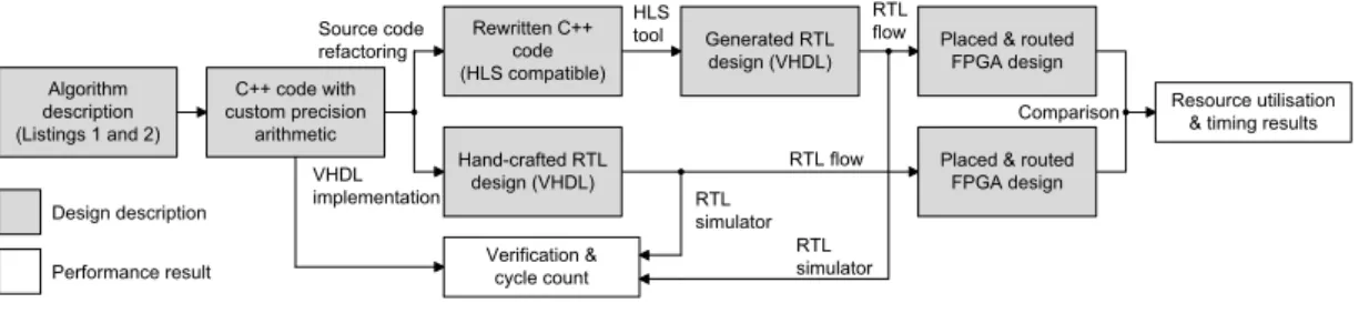
Algorithm description (Listings 1 and 2) C++ code with custom precision arithmetic Verification & cycle count RTL flow Rewritten C++ code (HLS compatible) Hand-crafted RTL design (VHDL) Generated RTL design (VHDL)
Placed & routed FPGA design
Placed & routed FPGA design
Resource utilisation & timing results HLS tool RTL flow Design description Performance result Source code refactoring VHDL implementation RTL simulator RTL simulator Comparison
Figure 2.1.: Design flow of the case study
• An efficient RTL implementation of the irregular tree-basedK-means clustering
al-gorithm which preserves the alal-gorithmic advantage over the conventional regular implementation. We show how the implementation can efficiently exploit the
dis-tributed memory architecture in FPGAs.
• A comparative case study using a data-flow centric clustering implementation and an implementation based on recursive traversal of a pointer-linked tree structure which incorporates data-dependent control flow. The case study comprises hand-written RTL and HLS implementations. Code transformations necessary to enable HLS of unsupported program features are highlighted.
• The use of on-chip dynamic memory allocation which allows us to allocate the aver-age amount of memory required during runtime instead of statically pre-allocating the worst-case amount resulting in a 57⇥reduction of on-chip memory resources. • An end-to-end QoR comparison between the automatically generated RTL code for
both variants and both functionally equivalent, hand-written RTL implementations. • An analysis of how efficiently specific program features are synthesised into RTL.
We propose source-to-source transformations that improve QoR by a factor of eight in terms of latency.
The two algorithms forK-means clustering form the basis of our case study. Fig. 2.1 shows our design flow. The initial C++model is modified in order to include custom precision
hand-written RTL design hand-written in VHDL (bottom branch, Section 2.3) and a C++-based HLS
design (top branch). The HLS implementation requires further code refactoring which we discuss in Section 2.4. The generated and hand-crafted RTL design entries are verified using standard RTL simulation tools. Finally, QoR is compared in terms of latency and resource usage taken from the placed and routed FPGA designs (Section 2.5). The evaluation flow in Fig. 2.1 is repeated for both clustering algorithms. The following section discusses both algorithms.
2.1. Background
The test cases we chose for this case study are two implementations of a clustering ap-plication, a technique for unsupervised partitioning of a data set commonly used in a wide range of applications, such as machine learning, data mining, radar tracking, image colour or spectrum quantisation. A popular technique for finding clusters in a data set is
K-means clustering, which partitions theD-dimensional point setX={xj},j=1, ...,Ninto
clusters{Si},i=1, ...,K, whereKis provided as a parameter. The goal is to find the optimal
partitioning which minimises the total sum of squared Euclidean distances (squared-error distortion) given in (2.1) whereµiis the geometric centre (centroid) ofSi.
J({Si})= K X i=1 X xj2Si xj µi 2 (2.1)
Finding optimum solutions to this problem is NP-hard [51]. A popular heuristic version uses an iterative refinement scheme. The standard algorithm begins by choosingKinitial centresZ= {µ1, ..., µK}sampled randomly from the point set. The setZis iteratively
re-fined until it no longer changes. On each iteration, it splitsXintoKpartitions, according to which is the nearest mean of each partition. These means (geometrical centres) form the next generation ofZ(Z0). Using one algorithm for this problem, which we refer to asLloyd’s
algorithm,N·K·Ldistances inD-dimensional space are computed whereNis the number of data points andL, the number of required iterations. Listing 1 shows pseudo code of
Listing 1Main kernel of Lloyd’s algorithm (one clustering iteration).
1: Parameters:
2: N,K 3: Input:
4: point setX={x1,x2, . . . ,xN}
5: initial centre setZ={µ1, µ2, ..., µK}
6: Output:
7: new centre setZ0={µ0
1, µ02, ..., µ0K}
8: Variables:
9: centroid informationC={c1,c2, ...,cK}
10: functionlloyds
11: for allxj2{x1,x2, ...,xN}do .iterate over all data points
12: i argmini0,µi02Z(||xj µi0||2) .find closest centre toxjamongKcandidates
13: ci selectith element inC
14: ci.wgtCent ci.wgtCent+xj
15: ci.count ci.count+1
16: updateciinC
17: end for
18: for allci2Cdo .update centre positions
19: µ0i ci.wgtCent/ci.count;
20: end for 21: end function
the main processing loop for one iteration of Lloyd’s algorithm. Line 12 searches amongK
candidate centres for the closest centre to a data pointxi. The indexiof this centre is used
to update the correct entry in the centroid information tableC(Lines 13-16). Ccontains
Kvector sums of data points which we refer to as ‘weighted centroids’ (wgtCent). After all data points have been processed, the final output centre set{µ01, µ02, ..., µ0K}is computed from the weighted centroids inC(Lines 18-20).
In contrast to massively parallel hardware implementations, sophisticated software im-plementations have been proposed which gain speed-up from search space reductions. Kanungoet al.[48] present one possible implementation. Theirfiltering algorithmorganises the data points in a multi-dimensional binary search tree, called a ‘kd-tree’, and finds near-est centres at each iteration using a tree traversal. To this end, the point set is recursively divided into two subsets. In each step, the axis-aligned bounding box of the subset is computed and subdivided. This leads to a (generally not perfectly balanced) binary
kd-tree structure whose root node represents the bounding box of all data points and whose children nodes represent recursively refined, non-empty disjoint bounding boxes. Each tree node stores the bounding box (bndBox) information as well as the number (count) and the vector sum of its associated points (the weighted centroid,wgtCent) which is used to update the cluster centres when each iteration completes. The weighted centroid of leaf nodes is the data point itself.
Listing 2 shows a simplified version of the recursive kernel function of the filtering al-gorithm for one iteration. During clustering, the tree is traversed starting from the root node. The set of input centres in Lloyd’s algorithm is replaced by sets of candidates for the closest centre to a subset of data points. The algorithm propagates multiple candidate sets down the tree. These are of variable size and are created and disposed at run-time. At each non-terminal visited tree node, the closest candidate centre to the mid point (midPoint) of the bounding box is found. Some of the remaining candidates are pruned if no part of the bounding box is closer to them than the closest centre (Line 22). The pruning greatly re-duces the number of computed distances since the average number of ‘close’ cluster-centre candidates is significantly smaller thanK. Additionally, entire sub-trees can be pruned if only one candidate remains. As the point set does not change during clustering, the kd-tree needs to be built up only once and the additional overhead is amortised over all iterations. In fact, our profiling results show that, on average, the tree construction demands less than 2% of the total computation required. Therefore, we perform the pre-processing in software and the FPGA accelerator discussed in the following focuses only on the tree traversal phase.
In light of this case study, we identify the most important features of both applications. Because the min-search in Listing 1 (Line 12) is implemented as afor-loop over K cen-tres, the main kernel of Lloyd’s algorithm consists of two nestedfor-loops with constant bounds. The simple control flow and inherent parallelism at the granularity of distance computations makes the computationally expensive algorithm suitable for hardware
im-Listing 2Main kernel of the filtering algorithm (one clustering iteration) [48].
1: Parameters: 2: N,K
3: Input: 4: kd-tree
5: initial centre set{µ1, µ2, ..., µK}
6: Output:
7: new centre setZ0={µ0
1, µ02, ..., µ0K}
8: Variables:
9: node in the kd-treeu
10: multiple sets of candidates for the closest centre to a point cloud (Z)
11: centroid informationC={c1,c2, ...,cK}
12: functionfilter(u,Z)
13: ifuis leafthen
14: i⇤ argmin
i0,µi02Z(||u.wgtCent µi0||2) .find closest centre tou.wgtCent
15: ci⇤ selecti⇤-th element inC
16: ci⇤.wgtCent ci⇤.wgtCent+u.wgtCent
17: ci⇤.count ci⇤.count+1
18: updateci⇤ inC
19: else
20: i⇤ argmini0,µi02Z(||u.midPoint µi0||2) .find closest centre tou.midPoint
21: Znew newcentre set .allocate new centre set (empty)
22: for allµj 2Zdo .prune candidate centres
23: if pruningTest(i⇤,µj,u.bndBox) is falsethen
24: Znew Znew[{µj}; .insert surviving candidates intoZnew
25: end if 26: end for
27: if|Znew|=1then
28: ci⇤ selecti⇤-th element inC
29: ci⇤.wgtCent ci⇤.wgtCent+u.wgtCent
30: ci⇤.count ci⇤.count+u.count
31: updateci⇤inC
32: deleteZnew .immediately delete allocatedZnew
33: else .recurse on children
34: FILTER(u.le f t,Znew);
35: FILTER(u.right,Znew);
36: deleteZnew .delete allocatedZnewon the way back
37: end if
38: end if 39: end function
40: for allci 2Cdo .update centre positions
41: µ0i ci.wgtCent/ci.count;
plementations so as to accelerateK-means clustering for real-time implementations ifN
andKare large. Computational parts of the filtering algorithm in Listing 2 are the closest centre searches (Lines 14, 20) and the candidate pruning (Line 22, containing two dis-tance calculations), and the centroid bu↵er update. The loops in the min-searches and
candidate pruning have variable bounds 2 k K. The implementation uses dynamic memory allocation (Line 21) and de-allocation (Lines 32, 36) enclosed in data-dependent conditionals. Memory space is freed upon backward traversal,i.e. after an allocated cen-tre set has been read twice. The implementation uses recursive function calls (beyond tail recursion) which requires the presence of astack. The stack is implicitly handled in the soft-ware program, but it needs to be explicitly implemented in an FPGA application. The data passed between recursive instances are the tree nodeuand the set of candidate centre setZ.
Previous hardware implementations of Lloyd’s algorithm are proposed in [52, 53, 54, 55, 56]. Pioneering work by Leeser et al.[52] implemented FPGA-clustering for the analysis of hyperspectral images. Their approach trades clustering quality for hardware resource consumption by replacing the Euclidean distance norm with multiplier-less Manhattan and Max metrics. This trade-o↵is extended to bit width truncations on the input data by
Estlicket al. [53] who report a speed-up of up to 200⇥over the software implementation. More recent work in [54] builds on the same framework and extends it by incorporating a hybrid fixed- and floating-point arithmetic architecture. These approaches aim to gain acceleration from an increased amount of parallel hardware resources for distance com-putations and nearest centre search. Contrary to these works, the first contribution in this thesis chapter is an efficient implementation of the filtering algorithm, which gains
accel-eration largely from search space pruning. Chenet al.[57] present a VLSI implementations forK-means clustering which is notable in that it, in line with our approach, recursively splits the data point set into two subspaces using conventional 2-means clustering. Logi-cally, this creates a binary tree which is traversed in a breadth-first fashion and results in computational complexity proportional to log2K. This approach, however, does not allow
implementation forK-means image clustering. The data structure stores the best candidate centre (or generally a few ‘best’ candidates) at its leaf nodes and is looked up for each data point. The tree is built independently of the data points,i.e. the pixel space is subdivided into regular partitions which leads to ‘empty’ pixels being recursively processed. Other disadvantages are that the tree needs to be rebuilt at the beginning of each iteration and that the centre lists are not pruned during tree traversal in the build phase, which are essential features of the filtering algorithm.
2.2. Analysis of the Filtering Algorithm
We analyse several properties of the filtering algorithm that provide insight into the ad-vantage over Lloyd’s algorithm. To this end, we profile a software implementation of the algorithm. The input data sets that we use throughout this chapter are point sets of
N=16384 three-dimensional real-valued samples. The data points are distributed among
128 centres following a normal distribution with varying standard deviation , whereas the centre coordinates are uniformly distributed over the interval [ 1,1]. Finally, the data points are converted to 16bit fixed-point numbers. We chooseK=128 initial centres
sam-pled randomly from the data set and run the algorithm either until convergence of the objective function or until a maximum of 30 iterations are reached. In addition to synthetic input data, we include a working set withN =16384 randomly sampled pixels from the
well-known Lena benchmark image and quantise the colour space intoK=128 clusters.
Note that the clustering output is exactly the same for both the implementation of Lloyd’s and the filtering algorithm.
The filtering algorithm can be divided into two phases: building the tree from the point set (pre-processing), and the repeated tree traversal and centre update (clustering phase). In order to obtain information about the computational complexity of both parts, we profile the software implementation of the algorithm using synthetic input data. Here, we chose the number of Euclidean distance computations performed as our metric for computational
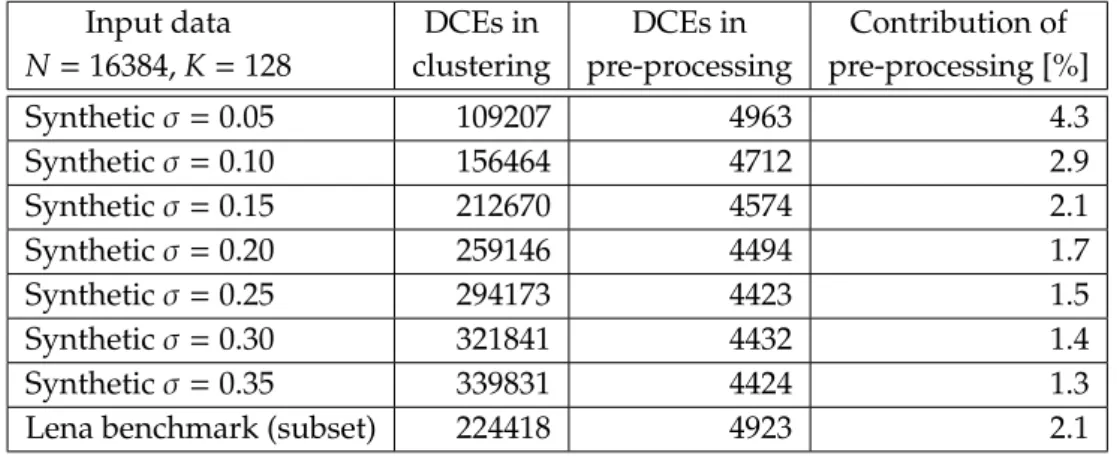
Table 2.1.: Computational complexity of the filtering algorithm broken down into cluster-ing and pre-processcluster-ing phases.
Input data N=16384,K=128 DCEs in clustering DCEs in pre-processing Contribution of pre-processing [%] Synthetic =0.05 109207 4963 4.3 Synthetic =0.10 156464 4712 2.9 Synthetic =0.15 212670 4574 2.1 Synthetic =0.20 259146 4494 1.7 Synthetic =0.25 294173 4423 1.5 Synthetic =0.30 321841 4432 1.4 Synthetic =0.35 339831 4424 1.3
Lena benchmark (subset) 224418 4923 2.1
complexity. Since the tree creation phase does not compute any distances but performs mainly dot product computations and comparisons, we introduce distance computation equivalents (DCEs) to obtain a unified metric for both parts which combines several op-erations which are computationally equivalent. Table 2.1 shows the profiling results of the computational complexity of the filtering algorithm broken down into clustering and pre-processing phases for di↵erent working sets. The parameter is varied such that the
synthetic input data ranges from well-distinguished clusters ( = 0.05) to a nearly
un-clustered point set ( = 0.35). For all cases, the number of DCEs performed during tree
creation is only a fraction of the total number of DCEs (2% geometric mean). Because of the small contribution of the pre-processing, we perform this part in software and the FPGA implementation described in the following section focuses on the tree traversal phase only.
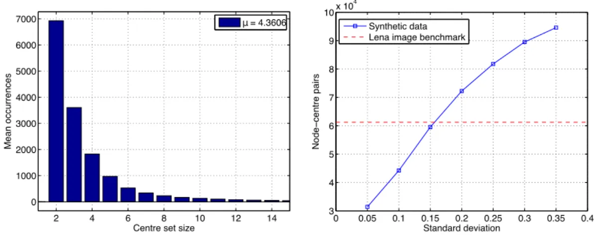
We also evaluate the search space pruning. The major complexity reduction is due to the fact that the repeated searches for the closest centre need to consider significantly fewer centres than Lloyd’s algorithm for which this number is alwaysK. Fig. 2.2 (left) shows the frequency of candidate centre set sizes averaged over all synthetic cases above. During tree processing, most sets contain only 2 or 3 centres and the average centre set size is 4.36 (3.78 for the Lena image benchmark), which shows the e↵ectiveness of the search space
2 4 6 8 10 12 14 0 1000 2000 3000 4000 5000 6000 7000
Centre set size
Mean occurrences µ= 4.3606 0 0.05 0.1 0.15 0.2 0.25 0.3 0.35 0.4 3 4 5 6 7 8 9 10x 10 4 Standard deviation Node − cent re pairs Synthetic data Lena image benchmark .
Figure 2.2.: Left: Frequency of candidate centre set sizes for synthetic input data. Right: Computational complexity of the filtering algorithm in terms of node-centre pairs (Lloyd’s algorithm has a constant complexity of 209.7⇥104point-centre
pairs for this data set).
the aggregate number ofnode-centre pairs,i.e. the cumulative number of candidate centres processed at the visited tree nodes per clustering iteration. This number is sensitive to the input data. Fig. 2.2 (right) shows the number of node-centre pairs over di↵erent values of
in the synthetic data sets. The complexity ranges from 31399 to 94590. We also include the Lena benchmark with 61230 node-centre pairs for a comparison with real-world data. For Loyd’s algorithm, an equivalent metric of data point-centre pairs can be defined which isN·K=2097152 for all input sets in Fig. 2.2. Even for unfavourable input data ( =0.35),
the filtering algorithm thus achieves a 22⇥reduction of search complexity. In a sequential software implementation [48], this reduction translates directly into a run-time advantage of the filtering algorithm. The next sections investigate if, how, and to what extent this result can be reproduced in hardware implementations.
2.3. RTL Implementations
This section describes efficient hand-crafted FPGA implementations of Lloyd’s and
Ka-nungo’s filtering algorithm implementations, which will be compared in Section 2.5.1. Both RTL implementations are fully pipelined designs and their computational parts
mainly consist of the same basic elements, Euclidean distance and dot product compu-tations, but their control structures and memory architectures are substantially di↵erent.
We made the source code of the RTL implementations discussed below available in an open source repository1. The following description motivates later discussion of how we
direct the HLS flow to produce competitive designs from a C description. Specific features discussed here and implemented later in the HLS flow (Section 2.4) will disclose particular limitations.
2.3.1. Lloyd’s Algorithm
The implementation consecutively fetches data points from memory, computes the Eu-clidean distance to each centreµi, 1 i K, and selects the closest centre before fetching
the next data point. The distance computation is fully parallelised for a parametric data point dimensionalityD. Parallelism is further increased by performingPdistance compu-tations concurrently which reduces the number of sequential steps per iteration fromN·K
to (N·K)/P. A centroid bu↵er stores the centroid informationCand maintains the
inter-mediate results during one iteration which are continuously updated. The accumulated weighted centroids (wgtCent) are then divided by thecountvalue at each index to obtain the centre positions for the next iteration. The data set memory and centroid bu↵er are
implemented as on-chip block random access memory (BRAM) and distributed look-up table (LUT) RAM, respectively. The position update uses a pipelined divider core.
2.3.2. Filtering Algorithm
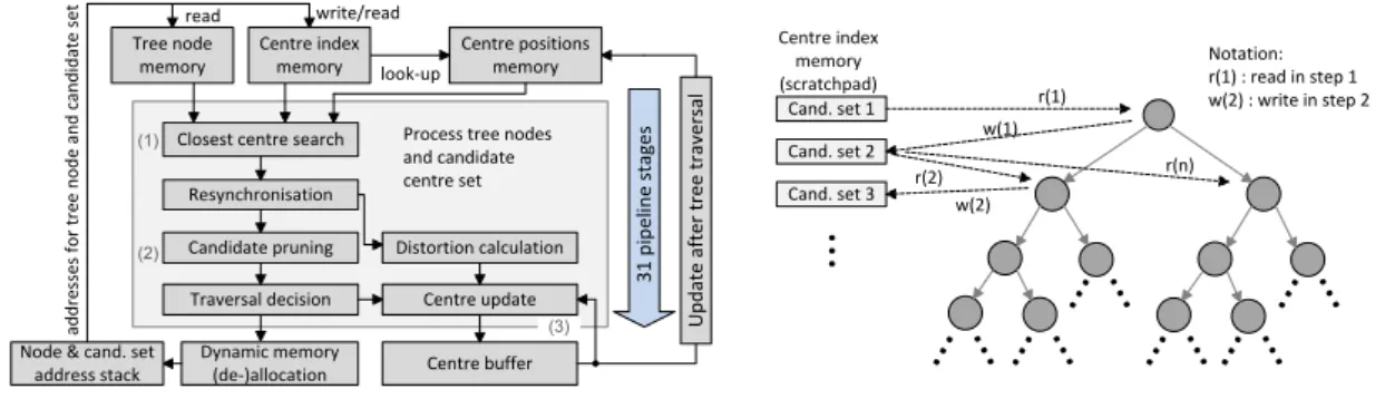
Fig. 2.3 (left) shows a high-level block diagram of our RTL design of the filtering algorithm. Our RTL implementation contains three computational kernels: 1) The closest centre search computes Euclidean distances to either the mid point of a bounding box or the tree node’s weighted centroid, followed by a min-search. 2) The pruning kernel performs two slightly modified distance computations to decide whether any part of the bounding box crosses the hyperplane bisecting the line between two centres. A more detailed description of the
Centre positions memory
Resynchronisation
Candidate pruning Distortion calculation Centre update Centre buffer Traversal decision Dynamic memory (de-)allocation ad d re ss es f o r tr ee n o d e an d c an d id at e se t write/read (1) (2) (3) 3 1 p ip el in e st ag es Cand. set 1 Cand. set 2 Cand. set 3 r(1) w(1) r(2) w(2) r(n) Notation: r(1) : read in step 1 w(2) : write in step 2 Process tree nodes
and candidate centre set Closest centre search
Centre index memory (scratchpad) look-up
Node & cand. set address stack Centre index memory read Tree node memory U p d at e af te r tr ee t ra ve rs al
..
.
... ..
.
... ..
.
... ..
.
... ..
.
... ..
.
... ..
.
Figure 2.3.: Left: FPGA implementation of the filtering algorithm. Right: Read-write accesses to the scratchpad memory for centre sets during tree traversal. pruning algorithm is given in [48]. Those centresµi for which the pruning test returns
false are flagged and no longer considered by subsequent processing units. 3) The centroid bu↵er is updated and used in the same way as for Lloyd’s algorithm. All three sub-kernels
are integrated in a pipelined, stream-based processing core. This core has a hardware la-tency of 31 clock cycles and can accept a node-centre pair on every other clock cycle. Thus, if fully utilised, the pipeline is usually filled with several tree nodes and their associated candidate centre sets.
The heart of the filtering algorithm is the traversal of the kd-tree which is implemented us-ing the recursive calls shown in Listus-ing 2. Our implementation controls this tree traversal using a stack which contains pointers to a tree node and to its associated set of candidate centres as well as the current set size. After fetching the pointers from stack, the data referenced by them is processed. At the output of the pipeline, we obtain a new traversal decision which is based on whether we have not yet reached a leaf node and whether there is more than one centre in the pruned candidate set left. If so, new pointers (left and right child and a new centre set) and the new set size are pushed onto the stack. Otherwise, nothing is pushed onto the stack. In the latter case, a pointer to a non-visited node further up in the tree will be fetched for processing in the next cycle. This process is repeated until the stack and pipeline are empty which terminates the tree traversal. Because all memories (tree nodes, centre indices, centre positions, centroid bu↵er, and stacks) are mapped to
physically disjoint memories, all accesses can be made simultaneously in each clock cycle.
Pipelining and Parallelisation
The profiling results in Section 2.2 show that a candidate set (associated with a tree node and processed item by item) has an average size of 4.36 centres in the scenarios considered here, which is smaller than the pipeline depth of 31 stages. In order to hide pipeline latency, we need to overlap the processing of multiple node-centre set pairs in the pipeline, which is possible in the absence of feedback dependencies. Fig. 2.3 (right) illustrates the read and write accesses. Memory accesses are indicated by dashed lines, pointer links are drawn as solid lines. The diagram shows that a read-write data dependency exists only between centre sets whose associated tree nodes have a direct parent-child relation. In fact, all pointers residing on the stack point to data structures that has already been written to and hence can be processed independently. The scheduler in the stack management fetches new pointers as described above as soon as the pipeline is ready to accept new data. Independent centre sets are read and written simultaneously using dual-port memory. For parallelism beyond pipelining the processing units are duplicated. To process independent subsets of such pairs, we split the tree intoPdisjoint sub-trees and distribute them across several computational units for parallel processing. We note that for both pipelining and parallelisation, we exploit knowledge about dependencies carried by data structures accessed through pointers.
Dynamic Memory Allocation
The centre index memory (Fig. 2.3, left) serves as ascratchpadmemory for storing centre sets and retaining them for later usage during the tree traversal. A new set is written when child nodes are pushed onto the stack and must be retained until both left and right child nodes have been processed. The memory space then can be freed and reused. The duration for which a centre set must be retained in memory depends on the shape of the (generally unbalanced) tree. The results in Section 2.2 are obtained under the assumption that the application can allocate as much scratchpad memory as needed. However, the requested
amount may exceed the available on-chip memory resources. The worst-case number of candidate sets isN 1 which is required in the case of a degenerate kd-tree where every internal node’s right child is a leaf and its left child is another internal node. If we consider an FPGA application supportingNmax=16384 data points and a maximum ofKmax=256
centres, we require (Nmax 1)·Kmax·log2Kmax⇡33.6 Mbits worst-case memory space which
consumes 912 on-chip 36k-BRAM resources (⇠89% in a medium-size Virtex 7 FPGA) and does not leave enough resources for the other memories in the implementation. However, in the average case, the tree is unlikely to be degenerate as described above and therefore the lifetime of a centre set is much shorter and the instantaneous memory requirement is significantly lower.
As a result of this resource advantage, we implement a memory management unit which dynamically allocates space and frees it once the candidate set has been read for the sec-ond time, rather than a static allocation. The implementation of the fixed-size allocator uses afree-list that keeps track of occupied memory space. In our implementation, the scratchpad memory and free-list are sized to accommodate an ‘average-case’ number of centre-candidate sets. Our approach is to limit the memory to a size ofB ⌧ N 1 sets. When inadequate memory is available to service an allocation request, the algorithm al-lows us to abandon the pruning approach and instead consider all candidate centres. This modification does not compromise the functionality of the algorithm, but it increases its run-time (the number of node-centre interactions). Fig. 2.4 shows the result of profiling the software implementation clusteringN=16384 pixels (RGB vectors) sampled from the
Lena image benchmark and the two extreme cases for synthetic data in Table 2.1. If we allow the algorithm to allocate memory for only a single centre, the search complexity degrades to the worst case of (2·N 1)·Knode-centre pairs to be examined. The search complexity, however, greatly decreases forB>10 in all test scenarios. We select a bound ofB=256 centre sets (16 36k-BRAMs) which practically causes no run-time degradation
100 101 102 103 104 105 0 10 20 30 40
Bound on memory size [number of allocated centre sets]
Node − cent re pairs (x10 5) Lena benchmark . Syntheticσ=0.05 Syntheticσ=0.35 selected bound B=256, 16 BRAMs worst−case bound B=16383, 912 BRAMs
Figure 2.4.: Trade-o↵between heap size and run-time of the filtering algorithm (profiling).
The next section describes the re-implementations of both algorithms using a C-based HLS tool, which finally allows us to compare the FPGA resource usage and speed of all four designs.
2.4. HLS Implementations
We choose Vivado HLS for this case study as an exemplary state-of-the-art tool which shares many similarities with other modern C-to-FPGA flows such as LegUp [22], ROCCC [24], Dwarv [25] and GAUT [26]. RTL generation is guided by synthesis directives which are manually invoked and configured. Exploring design options and optimisations using directives ideally does not require the source code to be altered. The most important directives we use to control the RTL generation are loop pipelining and loop unrolling directives. Loop pipelining overlaps loop iterations in the pipeline. The interval between the start of two iterations is given by the initiation interval (II). Loop unrolling is used to force parallel instantiations of the loop body. In order to remove the bottleneck of an insufficient number of memory ports in a parallelised application, on-chip memories can
be split into multiple banks using anarray partitioningdirective. As for LegUp, ROCCC, Dwarv and GAUT, the C-based input is restricted to a synthesisable subset. Vivado HLS allows pointers to be used as references to statically allocated arrays. However, it does not synthesise dynamic memory allocation (new,delete) and heap memory. In this thesis,
we refer to pointer variables which obtain their value from a call to thenew function as
heap-directedpointers. Other disallowed features are system calls, arbitrary pointer casting and arbitrary recursive functions.
Our goal is to bring the generated RTL designs produced by the HLS flow as close as pos-sible to the highly optimised manual RTL designs in the previous section. We distinguish between optimisations using synthesis directives and manual source code modifications.
2.4.1. Lloyd’s Algorithm
The C code for Lloyd’s algorithm corresponding to Listing 1 is directly synthesisable and does not contain any unsupported language features. We unroll allfor-loops over the three dimensions of the input data points which results in a parallel implementation of the distance computation||xj µi0||2. Most of the computation is contained within the
innerfor-loop which implements the min-search in Line 12 (boundK). Pipelining this loop (II=1) leads to performance comparable to hand-coded RTL. For acceleration beyond
pipelining, we control the degree of parallelism just as in the case of the manual RTL design by partially unrolling the outer loop to degreeP(replicating pipelines). In order to match the parallelism of computational units and memory ports, we partition the centre positions and centroid bu↵er arrays into Pbanks using the array partitioning directive.
Overall, using synthesis directives and a minor source code modification to ensure correct indexing of the parallel instances of the centroid bu↵er, we are able to produce an RTL
design which is architecturally similar to its hand-written counterpart.
2.4.2. Filtering Algorithm
The synthesisability of the main kernel as in Listing 2 requires the removal of the recursive function calls and the calls tonew(Line 21) anddelete(Lines 32, 36), and code transforma-tions to improve QoR of the synthesis of the pointer-linked data structures and the circuits operating on these.