An E-Model Implementation for
VoIP QoS across a Hybrid UMTS Network
A thesis submitted in fulfilment
of the requirements for the degree of
Master of Engineering in Computer Engineering
Jianguo Cao
BSc, BEng
School of Electrical and Computer Engineering
RMIT University
Melbourne, Australia
March 2009
Preface
Abstract
Voice over Internet Protocol (VoIP) provides a new telephony approach where the voice traffic passes over Internet Protocol shared traffic networks. VoIP is a significant application of the converged network principle. The research aim is to model VoIP over a hybrid Universal Mobile Telecommunications System (UMTS) network and to identify an improved approach to applying the ITU-T Recommendation G.107 (E-Model) to understand possible Quality of Service (QoS) outcomes for the hybrid UMTS network.
This research included Modeling the hybrid UMTS network and carrying out simulations of different traffic types transmitted over the network. The traffic characteristics were analysed and compared with results from the literature. VoIP traffic was modelled over the hybrid UMTS network and the VoIP traffic was generated to represent different loads on the network from light to medium and heavy VoIP traffic.
The VoIP over hybrid UMTS network traffic results were characterized and used in conjunction with the E-Model to identify VoIP QoS outcomes. The E-Model technique was implemented and results achieved were compared with results for other network types highlighted in the literature.
The research identified an approach that permits accurate Modeling of VoIP QoS over a hybrid UMTS network. Accurate results should allow network design to facilitate new approaches to achieving an optimal network implementation for VoIP.
Declaration
I certify that except where due acknowledgement has been made, the work is that of the author alone; the work has not been submitted previously, in whole or in part, to qualify for any other academic award; the content of the thesis is the result of work which has been carried out since the official commencement date of the approved research program; and, any editorial work, paid or unpaid, carried out by a third party is acknowledged; and, ethics procedures and guidelines have been followed.
Jianguo Cao 30 March 2009
Acknowledgement
I wish to express my sincere gratitude to Dr. Mark Gregory, Program Director for Network Engineering from School of Electrical and Computer Engineering for his guidance, encouragement, suggestions and support during the progress of the research and realization of the research. This also extends to all the staff of School of Electrical and Computer Engineering and RMIT University.
Special thanks also go to my wife for all her support and patience through all the time it took to complete this thesis.
Table of Contents Preface ... i Abstract... i Declaration... ii Acknowledgement ...iii Table of Contents ... iv
Table of Figures... vii
Table of Tables ... x List of Abbreviations ... xi 1 Introduction ... 1 1.1 Scope ... 3 1.2 Purpose ... 4 2 Background... 6 2.1 UMTS ... 6
2.1.1 UMTS network architecture ... 7
2.1.2 Core net work ... 7
2.1.3 UMTS Terrestrial Radio Access Network (UTRAN) ... 8
2.1.4 UMTS User Equipment ... 9
2.1.5 UMTS protocol stack ... 10
2.2 IP network and real-time applications ... 11
2.2.1 IP networks for real-time applications... 11
2.2.2 IP networks to support voice ... 12
2.2.2.1 Bandwidth requirement ... 13 2.2.2.2 Delay... 15 2.2.2.3 Jitter ... 16 2.2.2.4 Reliability ... 17 2.2.2.5 Interoperability ... 17 2.2.2.6 Integration with PSTN... 17 2.3 An overview of VoIP... 18
2.3.3 VoIP architectures ... 20
2.3.3.1 Infrastructure for Cisco’s AVVID ... 21
2.3.3.2 Applications for Cisco’s AVVID ... 22
2.3.4 VoIP standards and protocols ... 22
2.3.4.1 H.323 standard... 23
2.3.4.2 Session Initiated Protocol (SIP) standard ... 27
2.3.4.3 RTP and RTCP ... 30
2.4 Quality of Service (QoS) in VoIP... 33
2.4.1 Mean Opinion Score (MOS) ... 33
2.4.2 Delay... 33
2.4.3 Jitter ... 34
2.4.4 Packet loss ... 35
2.5 E-Model ... 37
2.5.1 E-Model algorithm ... 37
2.5.2 E-Model and MOS ... 38
2.5.3 E-Model parameters ... 38
2.6 Chapter summary... 40
3 Objectives ... 41
3.1 Assumptions ... 42
3.2 Research limitations ... 43
4 Experimental and Theoretic Work Completed... 44
4.1 VoIP over hybrid UMTS modeling ... 44
4.1.1 Opnet Modeler simulation environment... 44
4.1.2 Hybrid UMTS network Modeling ... 49
4.2 VoIP over Hybrid UMTS simulation ... 57
4.2.1 Configure the simulation ... 57
4.2.2 Profiles configuration ... 61
4.2.3 Application deployment ... 64
4.2.4 Running the simulation... 67
4.3 E-model implementation ... 68
4.3.1 Basic signal-to-noise ratio (SNR)... 70
4.3.3 Delay impairment factor, Id... 73
4.3.4 Effective Equipment Impairment Factor, Ie-eff ... 73
5 Results and Analysis... 76
5.1 End-to-end delay results ... 76
5.2 E-Model R factor results... 79
5.3 Results Analysis ... 81
6 Conclusions ... 85
6.1 Research review... 85
6.2 Thesis Summary ... 86
6.3 Research work summary... 87
6.4 Conclusion... 88
7 Future Research Work ... 89
8 Reference ... 91
Table of Figures
Figure 2-1: UMTS Architecture ... 7
Figure 2-2: UTRAN architecture... 8
Figure 2-3: UMTS protocol stack (PS domain)... 11
Figure 2-4: VoIP Network Connectivity ... 19
Figure 2-5: Typical IP Telephony Solution ... 21
Figure 2-6: Basic H.323 Architecture... 23
Figure 2-7: The H.323 suite in relation to the OSI model ... 24
Figure 2-8: A typical H.323 call setup life cycle ... 26
Figure 2-9: Basic SIP Architecture... 27
Figure 2-10: SIP protocol stack ... 28
Figure 2-11: A typical SIP call ... 29
Figure 2-12: RTP packet structure... 31
Figure 2-13: MOS rating with packet loss... 36
Figure 2-14: Effects of Random and Burst Packet Loss... 36
Figure 4-1: New Project - Project and Scenario names... 45
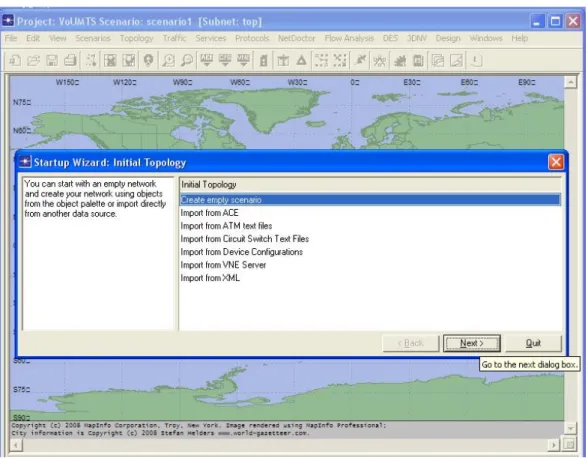
Figure 4-2: Start-up Wizard – Initial Topology... 46
Figure 4-3: Startup Wizard - campus network size ... 47
Figure 4-4: Start-up Wizard - Select Technology... 47
Figure 4-5: Start-up Wizard – Summarise... 48
Figure 4-6: Start-up Wizard - Object Palette... 49
Figure 4-7: VoIP over hybrid UMTS sketch topology ... 50
Figure 4-8: Hybrid UMTS Modeling - IP Backbone... 51
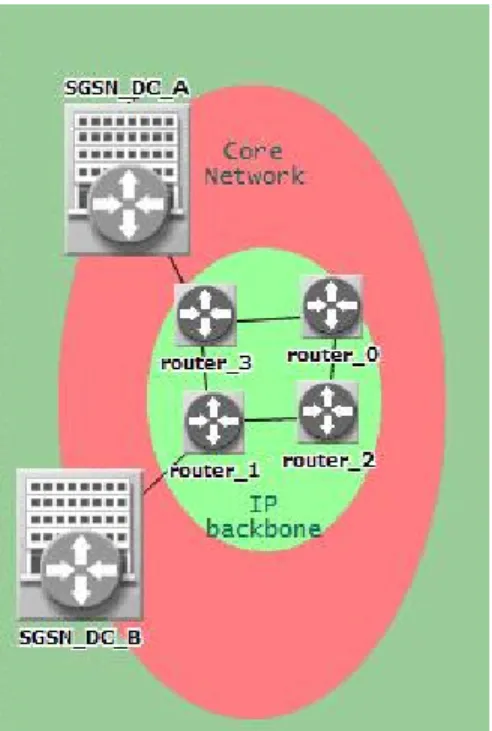
Figure 4-9: Hybrid UMTS Modeling - Core Network ... 51
Figure 4-11: Hybrid UMTS Modeling - End users added ... 53
Figure 4-12: Hybrid UMTS Modeling - UMTS parameters configuration for SGSN . 54 Figure 4-13: Hybrid UMTS Modeling - UMTS parameters configuration for UE ... 54
Figure 4-14: Hybrid UMTS Modeling - connecting to Internet ... 55
Figure 4-15: Hybrid UMTS Modeling - With IP network connected ... 56
Figure 4-16: Hybrid UMTS Modeling – Final simulation topology ... 57
Figure 4-17: Application Definitions - Number of Applications ... 58
Figure 4-18: Application Definitions - Predefined Applications ... 59
Figure 4-19: Application Definitions - Voice Application Options ... 59
Figure 4-20: Application Definitions - Voice settings Table ... 60
Figure 4-21: Application Definitions ... 60
Figure 4-22: Profile Definitions - Adding a new profile ... 61
Figure 4-23: Profile Definitions - Profile time-related attributes ... 62
Figure 4-24: Profile Definitions - Adding an application into a profile ... 63
Figure 4-25: Profile Definitions - Choosing the application to be added... 63
Figure 4-26: Profile Definitions - Application time-related attributes ... 64
Figure 4-27: Serve supported service configuration... 65
Figure 4-28: UE1 supported services ... 65
Figure 4-29: Enabling the SIP Server ... 66
Figure 4-30: UE0 supported profile... 66
Figure 4-31: Choose DES Results ... 67
Figure 5-1: Packet loss for G.711 ... 77
Figure 5-2: GSM-FR End-to-end delays ... 78
Figure 5-3: G729A End-to-end delays ... 78
Table of Tables
Table 2-1: Algorithms for voice compression and decompression ... 14
Table 2-2: IP bandwidth requirements for the most common coding algorithms ... 15
Table 2-3: Codec delay... 16
Table 2-4: MOS for common CODECs ... 33
Table 2-5: Definition of categories of speech transmission quality ... 38
Table 2-6: E-Model parameters... 39
Table 4-1: E-Model Inputs (G.107 Default) ... 70
Table 4-2: Provisional planning values for the equipment impairment factor, Ie ... 74
Table 4-3: Provisional planning values for the equipment impairment factor, Ie, and for packet-loss robustness factor, Bpl... 75
Table 5-1: End-to-end delays... 79
Table 5-2: R factor values ... 80
List of Abbreviations
3DES Triple Data Encryption Algorithm ACF Admission Confirm
ADPCM Adaptive Differential PCM AES Advanced Encryption Standard
ARJ Admission Reject
ATNAC Australasian Telecommunications Networking and Application Conference
AVVID Architecture for Voice, Video and Integrated Data
CC CSRC count
CELP Code-Excited Linear Prediction
CN Core Network
CODEC Compression and decompression
CS Circuit Switched
Diffserv Differentiated Services GGSN Gateway GPRS Support Node
GK Gatekeeper
GSM Global System for Mobile Communications
GW Gateway
IETF Internet Engineering Task Force Intserv Integrated Services
IP Internet Protocol
IPsec Internet Protocol Security
JTAPI Java Telephony Application Programming Interface LPC Linear Predictive Coding
M Marker
MCU Multipoint Control Unit MOS Mean Opinion Score
MPLS Multi Protocol Label Switching MP-MLQ MultiPulse-MultiLevel Quantization MSC Mobile services Switching Centre
P Padding
PCM Pulse Code Modulation PDN Packet Data Network
PoE Power over Ethernet
PS Packet Switched
PT Payload Type
QoS Quality of Service
RAQ RAS Admission Request RAS Registration Admission Status RCF Registration Confirm message RNC Radio Network Controller RRJ Registration Reject message RRQ RAS registration request
RTCP Real-time Transport Control Protocol RTP Real-time Transport Protocol
RTP/RTCP Real Time Protocol/Real Time Control Protocol SDP Session Description Protocol
SGSN Serving GPRS Support Node SIP Session Initiated Protocol SNR Signal-to-Noise Ratio
TAPI Telephony Application Programming Interface
TE Terminal Equipment
UA User Agents
UAC User-agent client UAS User-agent server UDP User Datagram Protocol
UMTS Universal Mobile Telecommunications System USIM UMTS subscriber identity module
UTRAN Radio Access Network
V Version
VLR Visitor Location Register VoIP Voice over Internet Protocol VPN virtual private network
W-CDMA Wideband Code Division Multiple Access
X Extension
1
Introduction
In the recent years, Voice over Internet Protocol (VoIP) has matured as a digital voice telephony technology. Uptake in the use of VoIP has increased as commercial solutions become available. Other factors include the decrease in quality differences between existing digital telephony and VoIP and the increase in bandwidth available to commercial and residential customers over which VoIP may be transported.
As a real-time digital application, VoIP requires a transmission system that includes low delay, jitter and packet loss rates to ensure that the Quality of Service (QoS) is acceptable. VoIP systems digitize and transmit analogue voice signals as a stream of packets over a digital data network. Internet Protocol (IP) (Information Sciences Institute, 1981) networks allow each packet to independently find the most efficient path to the intended destination. Packets associated with a single source may take many different paths to the destination when travelling over the network. With the different paths, arrivals will vary greatly due to delays and may be out of sequence or possibly not arrive at all. At the destination, the packets are re-assembled and converted back into the original voice signal.
However, most IP networks today were not designed for real-time, delay-sensitive voice or video traffic (Chandrasekharan et al., 2008). Kobayashi (Kobayashi et al., 2003) describes most IP networks as a best-effort transport system and subsequently there is no guarantee that VoIP speech quality will be equivalent to what is provided by the existing PSTN telephony services.
VoIP QoS mechanisms and application level controls have been developed to overcome some of the problems associated with best-effort IP networks and to maximize VoIP call quality including:
• Over-provisioning bandwidth to avoid congestion;
• Differentiated Services (Diffserv) (Seungchul, 2006), i.e. packet classification, marking and policing to give priority to certain classes of traffic;
• Integrated Services (Intserv) (Brewer et al., 2006), i.e. the use of signalled QoS to reserve network resources across the network.
• 802.1p (Hu et al., 2008); and
• Multi Protocol Label Switching (MPLS) (Ash et al., 2004)
VoIP services in wireless networks, such as UMTS (Oudelaar, 1994), are being progressively implemented. A benefit of VoIP over a wireless IP network is the mobility that is provided to users. Wireless networks have their own characteristics (Varshney and Malloy, 2001) which, together with a real-time applications transmission requirement, provide a challenge when a minimum QoS is required. To address this problem, firstly we need to develop tools to measure and monitor QoS. The ITU-T's E-Model (ITU-T, 2006) is a technique that provides a prediction of the expected voice call quality. The E-Model takes a wide range of telephony impairments into account, such as the impairment due to low bit-rate coding and one-way delay, and the telephony impairments associated with noise and echo. It can be used to assess the quality of voice calls over wired and wireless networks, based on circuit-switched and packet-switched technology. The E-Model is also useful for quality monitoring purposes, although currently there is no agreed-upon monitoring method for overall voice quality of VoIP (ITU-T, 2004).
The E-Model is based on a mathematical algorithm, with which the individual transmission parameters are transformed into different individual "impairment factors" that are assumed to be additive on a psychological scale. The E-Model algorithm also takes into account the combination effects for those impairments in the connection which occur simultaneously, as well as some masking effects (ITU-T, 2004). The E-Model estimates the relative impairments to voice quality when comparing different network equipment and network designs. It also provides a method to estimate the
subjective Mean Opinion Score (MOS) rating (ITU-T, 2003b) of the voice call quality over the different network environments.
The research presented in this thesis includes analysis of the E-Model as an effective means to measure QoS for VoIP over a hybrid UMTS network. As part of this research work, a paper has been presented in Australasian Telecommunications Networking and Application Conference (ATNAC 2008) (appendix A) which focuses on the relationship between CODEC scheme and end-to-end delay on VoIP calls over a hybrid UMTS network. To facilitate the analysis a simulated hybrid UMTS network was created. The simulation included a UMTS core network connected to a fixed IP network and end users at different points on the networks. The next goal was to analyse the initial simulation results and to modify the model with an implementation of the E-Model to permit QoS to be measured. The results from the modified model were analysed and compared with results from other studies identified during the literature review.
1.1 Scope
The research outcome was to implement the E-Model technique to provide an optimal approach to measure VoIP QoS over a hybrid UMTS network. The research was carried out in several steps:
• To implement the E-Model technique and analyse possible implementation variations,
• To analyse voice call quality over a hybrid UMTS network by simulating the network and applying an E-Model technique, and
• Finally, a discussion of possible future work.
The scope of this research included:
• Background investigation of the current research about VoIP and VoIP QoS over wireless networks
• An initial investigation of UMTS networks
• Detailed research and investigation of the E-Model including:
o Algorithms
o Parameters
o Approach to implementing the E-Model for different network types
• Implementation of a model using Opnet Modeler Version 14
o Hybrid UMTS network simulation
o VoIP application configuration
o Background traffic configuration o Data collection
o Data analysis
• Comparison of results with prior research and formulation of an E-Model implementation
o Comparison with results for other wireless network types
o Identification of approaches used for network specific E-Model
implementations
o Implementation of an E-Model to VoIP over a hybrid UMTS network
o Results analysis
1.2 Purpose
The purpose of this research was to investigate VoIP QoS over a hybrid UMTS network and to implement a VoIP QoS measurement approach in this particular
UMTS model for VoIP QoS study and the implementation of an E-Model technique to measure VoIP QoS across a hybrid UMTS network.
The research commenced with a literature investigation of key technologies, standards and concepts. The literature review is provided in Chapter 2. Chapter 3 includes a description of the simulation environment and details of the network configuration that was used for the study. The E-Model technique used during the research is described in Chapter 4. The simulation results and comparative analysis with VoIP QoS for other network types is provided in Chapter 5. The research results and conclusions are provided in Chapter 6. Finally, the opportunity for future research is discussed in Chapter 7.
2
Background
This Chapter provides a literature review in the areas of wireless networks, voice services and QoS. The key technologies, standards and concepts that form the basis for the research are reviewed and discussed.
This chapter begins with a description of UMTS wireless networks and discussion of the transmission of real-time connection oriented services over a UMTS network. A description of VoIP technologies and concepts are provided next, including VoIP over wireless networks such as UMTS. Combining UMTS networks and VoIP, the review moves on to considering QoS and how this is measured for wireless networks (Hernandez-Valencia and Chuah, 2000). The E-Model is introduced as a QoS measurement and prediction technique. Finally the use of a network simulation is discussed as a means to achieve an understanding of the operation of a real network.
2.1 UMTS
Universal Mobile Telecommunications System (UMTS) (Mason et al., 1996) is one of the third-generation (3G) cell phone technologies (Proctor, 2003). UMTS is broadly thought as the successor to Global System for Mobile Communications (GSM). It provides more capacity and bandwidth for voice and data services. Most UMTS networks use wideband code division multiple access (W-CDMA) as their underlying air interfaces, so UMTS is also referred as W-CDMA.
The UMTS provides support for both voice and data services (Liers and Mitschele-Thiel, 2005). The following data rates are targets for UMTS (Cisco, 2002):
• 144 kbps—Satellite and rural outdoor
• 384 kbps—Urban outdoor
2.1.1 UMTS network architecture
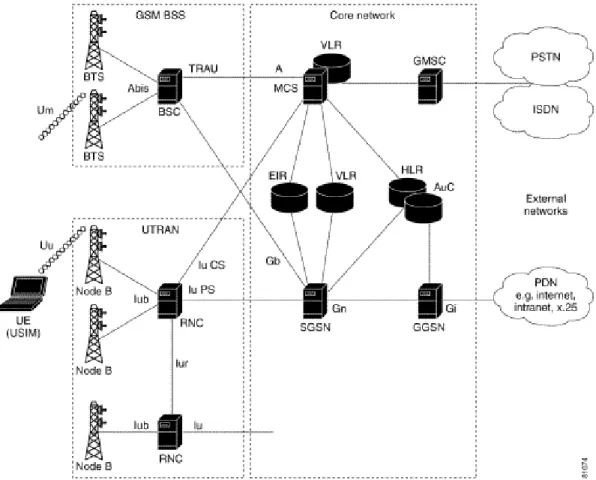
A UMTS network consists of three domains: Core Network (CN), UMTS Terrestrial Radio Access Network (UTRAN) and User Equipment (UE). Figure 2-1 (Cisco, 2002) illustrates the architecture of a UMTS network.
Figure 2-1: UMTS Architecture
2.1.2 Core net work
The UMTS Core Network is based on GSM/GPRS network. The main functions of the core network are to transport, switch and route user traffic (both circuit switched and packed switched traffic).
The UMTS core network is contains circuit switched and packet switched elements. Circuit switched elements include: Mobile services Switching Centre (MSC), Visitor
location register (VLR) and Gateway MSC. Packet switched elements include: Serving GPRS Support Node (SGSN) and Gateway GPRS Support Node (GGSN). Some network elements, like EIR, HLR, VLR and AUC are both circuit switched and packet switched elements (Cisco, 2002).
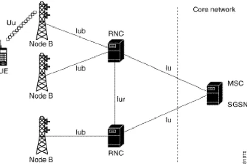
2.1.3 UMTS Terrestrial Radio Access Network (UTRAN)
The UMTS Terrestrial Radio Access Network (UTRAM) includes two new network elements: the Radio Network Controller (RNC) and Node B. The RNC connects to one or more Node B elements. Each Node B can provide service to multiple cells. Figure 2-2 (Cisco, 2002) illustrates the architecture of the UTRAM domain.
Figure 2-2: UTRAN architecture
The functions of Node-B are (Hawwar et al., 2006):
• Air interface Transmission / Reception
• Micro Diversity
• Error Handing
• Closed loop power control
The functions of RNC are (Matusz et al., 2004):
• Radio Resource Control
• Admission Control
• Channel Allocation
• Power Control Settings
• Handover Control
• Macro Diversity
• Ciphering
• Segmentation / Reassembly
• Broadcast Signalling
• Open Loop Power Control
2.1.4 UMTS User Equipment
The UMTS user equipment (UE) is the mobile equipment with the UMTS subscriber identity module (USIM). The USIM is a card that inserts into the mobile equipment and identifies the subscriber to the core network (Cisco, 2002).
The USIM card has provides the following functions (Cisco, 2002):
• Supports multiple user profiles on the USIM
• Provides security functions
• Provides user authentication
• Supports inclusion of payment methods
• Supports secure downloading of new applications
The UMTS UE can operate in one of three modes of operation (Cisco, 2002):
• PS/CS mode—The UE is attached to both the packet-switched (PS) and circuit-switched (CS) domain, and the UE can use both PS and CS services in the same time.
• PS mode—The MS is attached to the PS domain and uses only PS services (but allows CS-like services such as voice over IP).
• CS mode—The MS is attached to the CS domain and uses only CS services.
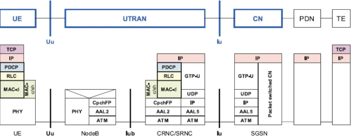
2.1.5 UMTS protocol stack
In this research project, the PS (packet switch) domain of the UMTS network has the full attention. Being looked at from the upper layer, the PS domain functions like normal IP network (Jin and Kriaras, 2000). Figure 2-3 (Loffelmann, 2000) illustrates a scenario that a UE that established a TCP connection to a Terminal Equipment (TE) connected to an external packet data network (PDN). As TCP and UDP are both running on top of IP, it will be shown the similar protocol stack if UDP was used instead of TCP (Koth et al., 1996). In addition to this, RTP can be implemented to transmit voice (MacKnight et al., 2004).
Figure 2-3: UMTS protocol stack (PS domain)
2.2 IP network and real-time applications
As a voice communication tool, VoIP is a real-time application which is very delay-sensitive. Let us have a look at the IP networks for real-time applications.
2.2.1 IP networks for real-time applications
IP networks are “best-effort networks”, which look like they are not suitable for Real-Time applications (Ghiasi and Po-Kuan, 2006). But IP networks have had some success in supporting real-time applications as benefit of the widely roll out of broadband Internet access (Upkar Varshney, 2002). Real-Time IP applications such as voice, video, and interactive gaming are becoming the wave of growth for IP networks. These bandwidth-intensive applications are referred to be as Real-Time applications because, unlike best-effort applications, they must be transported through a network with minimal delay or latency (Al-Mouhamed et al., 2005).
IP networks are highly dynamic. Any outage or change in the network will cause routing path re-calculating for the entire network (Yufei et al., 2001). This characteristic comes from the original design of the IP networks, which are designed for best-effort applications. It reduces the need for high reliability in the individual network elements (routers) or links, because after finding any outage or change, the network can simply re-converge and find an alternative route. This dynamic and self-rconverge network model is perfectly suited to best effort applications, such as
e-mail, web browsing and non-critical data transmitting, which are not time-sensitive and tolerant to some packet loss.
In contrast, real-time applications, such as voice/video calls, are very delay-sensitive and must be supported by a highly stable network (Jae-Chang, 1994). To support real-time applications, some improvements are required for the IP networks: reliability, stability and faster convergence (Fineberg, 2002). With the reliability of the network elements (routers and links) and the stability of the network, fewer interruptions would occur, and when interruptions occur, the faster convergence can reduce the impact. By addressing these three basic requirements, the IP networks can achieve the reliability and stability required to support new Real-Time services.
2.2.2 IP networks to support voice
In order for consumers to accept VoIP, the quality of VoIP calls should be equal to the traditional PSTN voice services. But since VoIP shares the same network with data transmitting either in the Internet or Intranet, it must compete with other applications for the limited network bandwidth. That brings up some requirements that VoIP needs to run over IP networks. VoIP, as a real-time, delay-sensitive application has special performance needs for bandwidth, delay, jitter and packet loss.
Bandwidth: A VoIP call needs a certain transmitting speed to continue the conversation. That means VoIP utilizes a certain bandwidth on the network when a continuous call is in progress. For example, a VoIP call using the high quality G.711 codec will utilize approximately 90 Kbps, while a standard video call can utilize 440 Kbps.
Delay: That is the time for the voice to travel from the speaker to the listener. The acceptable delay for a listener would fall into the range between 100 and 200 milliseconds.
Jitter: It is the variation in latency over time, and it must be small enough to provide with acceptable voice quality.
Packet loss: Packet loss begins to effect voice quality when its percentage reaches curtain value.
Most of the non-real-time applications can perform well without meeting these requirements. By using a buffer or re-transmitting the data, the up-layer protocols can convert all these shortcomings into a delay, which is not critical for a non-real-time application. People generally do not expect real-time response for normal data applications. However, for voice, the situation is dramatically different. The high voice quality provided by the PSTN service has led to high end user expectations for all the voice communications. VoIP with poor performance is unacceptable and virtually unusable. As previously mentioned, VoIP has some performance needs to make it workable. There are also some more issues in transmitting voice over IP networks. The followings are some detailed discussion about their requirements and issues.
2.2.2.1 Bandwidth requirement
Telco quality voice requires sampling at 8 KHz. The bandwidth then depends on the level of quantization. With Linear quantization at 8 bits/sample or at 16 bits/sample, the bandwidth is either 64 Kbps or 128 Kbps.
In order to get VoIP calls at a Telco quality, two different approaches can be attempted. One is to transmit voice in the highest quality, which needs unrestricted bandwidth. Another approach is to transmit voice at a certain quality, which is competitive with PSTN call quality. By using the second approach, the required bandwidth can be reduced to a reasonable low level. Some source data are highly redundant, for example, a digital signal contains many strings of zeroes (or ones), and it will be economical to transmit a code indicating that a string of zero (or one) follows along with the length of the string. Compression and decompression (CODEC) of digital signals is a means of reducing the required bandwidth or transmission bit rate. Many different algorithms for compression and decompression of digital codes have been constructed. Pulse code modulation (PCM) and adaptive differential PCM (ADPCM) are examples of "waveform" CODEC techniques. Waveform CODECs are compression techniques that exploit the redundant characteristics of the waveform itself. In addition to waveform CODECs, there are source CODECs that compress
speech by sending only simplified parametric information about voice transmission; these CODECs require less bandwidth. Source CODECs include linear predictive coding (LPC), code-excited linear prediction (CELP) and multipulse-multilevel quantization (MP-MLQ). Coding techniques for telephony and voice packet are standardized by the ITU-T in its G-series recommendations. Some algorithms for voice compression and decompression are given in the Table 2-1.
Input Range Transmission Rate Standard
Linear Predictive Coding Algorithm 64 Kbps LPC-10, G.711
Code Excited Linear Prediction (CELP) 8 Kbps G.729, G.729A
32 Kbps Adaptive Differential Pulse Code Modulation (ADPCM)
32 Kbps G.721
Table 2-1: Algorithms for voice compression and decompression
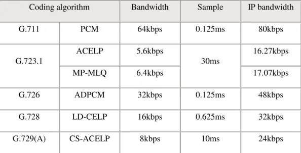
In order to transmit the voice information over IP networks, besides the actual bandwidth the voice data used, some extra bandwidth is required to cover adding the heads for each packet transmitted. These headers are IP, UDP and RTP. An IPv4 header is 20 octets; a UDP header is 8 octets and an RTP header is 12 octets. The total length of this header information is 40 octets (bytes), or 320 bits. These headers are sent each time a packet, containing voice samples, is transmitted. The additional bandwidth occupied by this header information is determined by the number of packets, which are sent each second. For example, if one packet carries the voice samples representing 20 milliseconds, the 50 such samples are required to be transmitted in every second. Each sample carries an IP/UDP/RTP header overhead of 320 bits (Perkins and Crowcroft, 2000). Therefore, in each second, 16,000 header bits are sent, which means an extra of 16 Kbps bandwidth is required. Islam (Islam et al., 2005) provides a detailed description of how to calculate the bandwidth requirements for VoIP over IP network transmission. Table 2-2 shows the IP bandwidth requirements for the most common coding algorithms.
Coding algorithm Bandwidth Sample IP bandwidth G.711 PCM 64kbps 0.125ms 80kbps ACELP 5.6kbps 16.27kbps G.723.1 MP-MLQ 6.4kbps 30ms 17.07kbps G.726 ADPCM 32kbps 0.125ms 48kbps G.728 LD-CELP 16kbps 0.625ms 32kbps G.729(A) CS-ACELP 8kbps 10ms 24kbps
Table 2-2: IP bandwidth requirements for the most common coding algorithms
2.2.2.2 Delay
Delay is a vital element for VoIP, because Voice traffic is real-time traffic and if there is too long of a delay in voice packet delivery, speech will be unrecognizable and unacceptable. An acceptable delay is less than 200 milliseconds. Delays are caused by a number of different factors. There are basically two kinds of delay in VoIP networks: Propagation delay and Handling delay.
Propagation delay is caused by the characteristics of the speed of light/electrical signal travelling via a fiber-optic or copper medium of the physical layer of the network. Much cannot be done about the propagation delay, but sometimes it is a big part of the whole delay. It takes light about 100 ms to travel around the Earth, so a call to someone on the other side of the Earth would cause propagation delay of about 50 ms, which is a quart of the maximum acceptable delay.
Handling delay is caused by the devices that handle voice information and have a significant impact on voice quality in a packet network.
One big part of the handling delay comes from the network. This delay is an accumulation of queuing delay in network routers and switches.
Handling delay also includes the time a system takes to generate a voice packet, it may take 5ms to 20ms to generate a frame depending on the system, and usually one or more frames are placed in one voice packet.
Another contribution to this delay is the time taken to move the packet to the output buffer and the time the packet waiting in the output buffer before being processed. Also, CODECs induce delay as well. There are various coding schemes available. Table 2-3 shows the best and worst case coding delays for the common CODECs. G711 is not listed in the table, because it does not compress the PCM sample and therefore, it does not experience a codec delay.
Codec Rate Minimum Sample block Worst Case Codec Delay
ADPCM, G.726 32 Kbps 10 ms 10 ms
CS-ACELP, G.729A 8.0 Kbps 10 ms 10 ms
MP-MLQ, G.723.1 6.3 Kbps 30 ms 20 ms
MP-ACELP, G.723.1 5.3 Kbps 30 ms 20 ms
Table 2-3: Codec delay
2.2.2.3 Jitter
Jitter is defined as a variation in delay of VoIP packets reaching the receiver. The VoIP receiver expects packet flows to arrive at equal intervals of time, so it can play out a continuous voice stream. Any variation in that arrival of a packet creates jitter. Normally jitter can be compensated by using a jitter buffer for playing out the audio smoothly, but this way introduces some extra delay.
2.2.2.4 Reliability
Although IP networks are best-effort networks, the traditional data communication provides reliable end-to-end communication between two users by using mechanisms in up-layer protocols (TCP is a good example of this). It uses checksum and sequence numbering for error control and some form of negative acknowledgement with a packet retransmission handshake for error recovery. The negative acknowledgement with subsequent re-transmission handshake, introduces more than a round trip delay to transmission. For real-time applications, especially for VoIP, retransmitted packets might be entirely useless, so VoIP networks should leave the proper error control and error recovery scheme to higher communication layers. They can, thus, provide the level of reliability required, taking into account the impact of the delay characteristics. Although TCP/IP provides reliable connection, it is at the cost of packet delay or higher network latency. On the other hand, UDP is faster compared to TCP. Therefore, VoIP uses UDP as the transport level protocol. Reliability is built into higher layers. RTP over UDP/IP is usually used for voice and video communication.
2.2.2.5 Interoperability
In order to communicate using different products from different vendors, standards have to be confirmed. Currently the main standards are the H.323 and SIP. H.323 from ITU-T was the first set of agreed-upon standards, so it is quite popular. However, SIP from IEFT is becoming more acceptable. It is relatively lightweight and easily scalable, so almost all the vendors are developing products on it.
2.2.2.6 Integration with PSTN
In the world that PSTN is still the most used telephony, VoIP needs to be integrated with PSTN to be more accepted and deployed. This will make PSTN and IP telephony networks appear as a single network to the end users and has been achieved through the use of gateways between the Internet on one hand and PSTN on the other.
2.3 An overview of VoIP
In modern society, it is considered to be essential for any business to have Internet access and Intranet. More and more communications are in digital forms and transported via packet networks such as IP, ATM, and Frame Relay. Since data traffic is growing dramatically, there comes a lot of interest in transporting voce over the data networks. Transporting voice communications using Internet Protocol (IP) is usually called “Voice over IP” or VoIP, and has became very attractive by giving the low cost.
2.3.1 An introduction of VoIP Systems
In the 1990s, a number of individuals in research environments, both in educational and corporate institutions, started researching the passing of voice over IP networks, especially corporate intranets and the Internet. This technology is commonly referred to today as VoIP. In simple terms, it digitizes the audio stream and breaks it into small chunks, then transmits those chunks over an IP network to the receiver. These chunks are collected and reassembled. This process converts a two people audio communication stream into a normal telephone call.
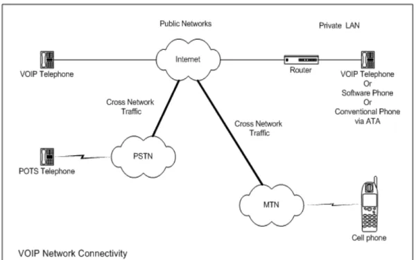
VoIP brings significant change in the way that people communicate. It gave users an option of using pure IP-based phones, including desktop computers, wireless phones and laptops, in addition to the telephones we have today. In Figure 2-4 (Net, 2008) shows how VoIP network can be connected and communicate with the normal PSTN network and Mobile network.
Figure 2-4: VoIP Network Connectivity
In the same concept, if we have sufficient bandwidth, we also have the ability to use videophone calls, much like those seen in science fiction movies. We can call home to see and talk to the family rather than just calling home to talk.
2.3.2 Importance and benefits of VoIP
First of all, VoIP offers significant cost savings relative to the PSTN. Remote branches and users can use VoIP to bypass the long-distance carriers, which charge them per minute. What they need to pay is a monthly Internet access fee.
Another aspect of VoIP is integration. VoIP gives us the ability to integrate a stand-alone telephone with the personal computer. People can use a computer for voice communications (softphones). VoIP also allows something else: the ability to use a single high-speed Internet connection for both voice and data communications. This idea is commonly referred to as convergence and is one of the primary drivers for corporate interest in the technology. The benefit of convergence should be fairly
obvious: by using a single data network for all communications, it is possible to reduce the overall maintenance and deployment costs.
In short, VoIP enables people to communicate in more ways and with more choices.
2.3.3 VoIP architectures
A whitepaper (Networks, 1998) suggested that to design and implement VoIP architectures, product developers are face challenges in 5 areas:
1. Voice quality should be comparable to what is available using the PSTN, even over networks having variable levels of QoS.
2. The underlying IP network must meet strict performance criteria including minimizing call refusals, network latency, packet loss, and disconnects. This is required even during congestion conditions or when multiple users must share network resources.
3. Call control (signalling) must make the telephone calling process transparent, so that the callers need not know what technology is actually implementing the service. 4. PSTN/VoIP service inter-networking (and equipment interoperability) involves gateways between the voice and data network environments.
5. System management, security, addressing (directories, dial plans) and accounting must be provided, preferably consolidated with the PSTN operation support systems. Among many industry solutions, AT&T’s Common VoIP Architecture and Cisco’s AVVID are becoming outstanding. Cisco’s AVVID (Architecture for Voice, Video and Integrated Data) is a well-known architecture and worthy to discuss. Cisco presents a typical IP telephony solution employing the Cisco AVVID network infrastructure (Cisco, 2003). The Cisco AVVID IP Telephony solution is the leading converged network telephony solution for organizations that want to increase productivity and reduce costs associated with managing and maintaining separate voice and data networks. The flexibility and sophisticated functionality of the Cisco
of emerging applications, such as desktop IP telephony, unified messaging, desktop collaboration, enterprise application integration with IP phone displays, and collaborative IP contact centres. These applications enhance productivity and increase enterprise revenues. Figure 2-5 (Cisco, 2003) illustrate a very typical VoIP solution.
Figure 2-5: Typical IP Telephony Solution
2.3.3.1 Infrastructure for Cisco’s AVVID
Cisco’s AVVID is built on the multiprotocol routers and multilayer switches that are used to build up enterprise networks. Many Cisco products have the ability to terminate both analogue and digital voice interfaces for integration with PBX or PSTN.
As we discussed, to be able to transmit voice traffic over IP network, some requirements (such as QoS and bandwidth) need to be provided. The Cisco multilayer LAN switches offer the required features and functionality to achieve this goal. Advanced traffic classification, interface queuing and bandwidth provisioning techniques are required to ensure voice and videos are effectively transported. Some switches provide the required functionality including the ability to support line power by using Power over Ethernet (PoE).
2.3.3.2 Applications for Cisco’s AVVID
There are lots of applications which can be enabled on a Cisco AVVID network, such as VoIP, unified messaging and the IP Contact Centres. Here, we focus on VoIP. A PBX can be eliminated and replaced with VoIP over a converged network. Cisco uses CallManager to enable VoIP on an AVVID network. The Cisco’s CallManager provides call-control functionality. When CallManager is used in conjunction with the IP telephones or soft telephone applications, it can provide the PBX functionality in a distributed and scalable way. Cisco CallManager severs can be networked via IP and provide fall back to the PSTN, if required.
Cisco Systems is promoting the use and adoption of open standards and is participating actively in the definition and approvals process for a number of standards and open protocols in this arena. Cisco CallManager contains a number of interfaces that enable communications with external applications. That includes, Telephony Application Programming Interface (TAPI), Java Telephony Application Programming Interface (JTAPI), EXtensible Markup Language (XML) through HyperText Transfer Protocol (HTTP) messages, and H.323 endpoints. Enterprises can combine these interfaces within a single application, to develop their own applications with more features.
2.3.4 VoIP standards and protocols
The most popular and accepted VoIP standards are H.323 from ITU-T and SIP from IETF.
2.3.4.1 H.323 standard
H.323 is an ITU recommendation for multimedia communications over connectionless networks that do not guarantee Quality of Service (QoS), such as IP networks. The standard covers point-to-point communications and multipoint conferences. It addresses call control, multimedia management, bandwidth management, and interfaces between LANs and other networks.
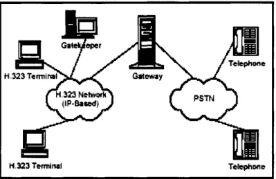
Figure 2-6 illustrates the elements of H.323 architecture and their connection. The elements are User Terminals, GateWays (GWs), Multipoint Control Units (MCUs,) and GateKeeper (GKs).
Figure 2-6: Basic H.323 Architecture
User terminals are normally IP phones or softphones. They provide real-time two-way communications. Gateways are used for integration with the PSTN network. They perform the translation of the signalling and media streaming exchanged between VoIP and PSTN networks. Multipoint control units are used for conferencing. All terminals participating in the conference establish a connection with the MCU. Gatekeepers are responsible for all authorization, address resolution and bandwidth management. Terminals, gateways and MCUs are generally called “Endpoints”.
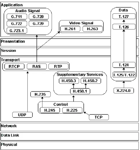
There are many protocols involved in a H.323 system. Figure 2-7 (Protocols, 2008) shows the H.323 protocols in relation to the OSI model.
Figure 2-7: The H.323 suite in relation to the OSI model
The Registration Admission Status (RAS) protocol is the key protocol for GKs. When an endpoint joins the network, it sends the GK a RAS registration request (RRQ), which contains information about itself such as the endpoint address and user alias. If the GK accepts the registration, it sends a Registration Confirm message (RFC). Otherwise, it sends a Registration Reject message (RRJ). RAS messages are carried in UDP packets.
permission by sending a RAS Admission Request (ARQ) message, which contains information of the destination endpoint. The GK may reject the request by sending back an Admission Reject (ARJ) message with a variety of reasons such as “not enough bandwidth” or “cannot find destination”. More commonly, the GK will grant permission for the call. The GK resolves the address (either locally, by consulting another GK, or by querying some other network service) and then sends back an Admission Confirm (ACF) message containing the actual destination address, alias, etc. Once the address of the remote endpoint is resolved, the endpoint will use H.225 Call Signalling, in order to establish communication with the remote endpoint. Many H.225 messages are used to establish the call, including Setup and Setup acknowledge, Call Proceeding, Connect, Alerting, Information, Release Complete, Facility, Progress, Status and Status Inquiry and Notify. Endpoints must notify their gatekeeper that they are in a call.
Once a call has concluded, a device will send a Release Complete message. Endpoints are then required to notify their gatekeeper that the call has ended. As soon as the call has initialised the two endpoints start using H.245 call control protocol. H.245 provides capabilities such as capability negotiation, master/slave determination, flow control, etc. The two endpoints agree on the nature of the information that will be exchanged through the media channel and its format (compression, encryption, etc.). After these procedures, the Real Time Protocol/Real Time Control Protocol (RTP/RTCP) starts to transfer the media data according to the endpoints’ capabilities. The actual media communication starts. Figure 2-8 (VoIPForo, 2006) shows the whole process of establishing and releasing an H.323 voice call. Some particular types of message are not discussed here.
2.3.4.2 Session Initiated Protocol (SIP) standard
The Session Initiation Protocol (SIP) is an Internet Engineering Task Force (IETF) standard protocol. SIP is a signalling protocol that can set up and tear down media communications such as voice/video calls over Internet. Although SIP was introduced later than H.323, it is playing a major role in VoIP.
Figure 2-9 (Cisco, 2007) shows the basic SIP architecture. The SIP architecture identifies two basic components: SIP users, normally called SIP User Agents (UA), and SIP Servers.
Figure 2-9: Basic SIP Architecture
A user agent can be a SIP enabled IP phone or just a softphone. It can function in one of the following roles:
User-agent client (UAC): A client application that initiates the SIP call request. User-agent server (UAS): A server application that contacts the user when a SIP request is received and that returns a response on behalf of the user.
A SIP endpoint normally can function as both a UAC and a UAS, but it only can function as one in a conversation. The endpoint that initiated the SIP call request becomes the UAC and the remote endpoint becomes the UAS.
In SIP architecture there are three different server groups:
SIP Registrar Server: A server receives and processes registration message from UACs regarding their current user location. Registrar servers are often co-located with a redirect or proxy server.
SIP Proxy Server: A server forwards the SIP messages to multiple proxy servers, in order for the SIP messages to reach their destinations. Proxy servers can provide functions such as authentication, network access control, routing, etc.
Redirect Server: A server helps endpoints to find the desired address by redirecting them to another server.
SIP uses Session Description Protocol (SDP) to describe the sessions that will be set up. A SIP INVITE message includes a SDP message as a payload, describing the capabilities of calling agent and then both parties negotiate on the capabilities of the session will be set up. Figure 2-10 (Fox and Uyar, 2001) indicates the protocols involved in a SIP voice call and their relationship.
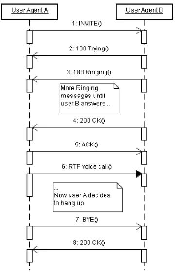
The procedures of establishing a SIP call under different circumstances are slightly different. In some scenarios, UA needs to contact with Servers to be able to find out and connect with remote endpoint. Figure 2-11 (Proulx, 2007) shows a typical SIP call process without involve of any servers.
Figure 2-11: A typical SIP call
User Agent A (UA A) sends a SIP request "INVITE" to User Agent B (UA B) to indicate its wish to talk to UA B. This request contains the details of the voice streaming protocol. The Session Description Protocol (SDP) is used in the payload for this purpose. The SDP message contains a list of all media CODECs supported by UA A. After UA B received the request, it confirms the receiving with UA A. While the
phone rings, UA B sends provisional messages (ringing) to UA A. When UA B accepts the call, it sends an OK response to UA A. In the payload of the response, there's another SDP message. It contains a set of media CODECs that are supported by both user agents. At this point both parties are officially in the call. All types of SIP requests are accepted using 200-type responses. UA A finally confirms with an ACK message. Both user agents are now connected using the method selected in the last SDP message. At the end of the communication session, one of the users hangs up. At this point this UA A sends a new request, BYE. The other user's user agent accepts the request and replies with an OK message. The call is disconnected.
2.3.4.3 RTP and RTCP
In both SIP and H.323 standards, Real-time Transport Protocol (RTP) and Real-time Transport Control Protocol (RTCP) are used to transport the voice over the Internet. RTP/RTCP were designed for providing end-to-end network transport functions suitable for applications transmitting real-time data, such as audio, video or simulation data, over multicast or unicast network services (Schulzrinne, 2003). RTP is the one to carry the real-time data, while RTCP is to monitor the transmission QoS and generate the statistic information for the participants in the session.
As called Real-time transport protocol, RTP itself even does not provide guaranteed timely delivery. Also, it does not have any mechanism to ensure the QoS, such as in-order delivery and packet re-delivery. Despite this, RTP, along with RTCP, is one of the foundational VoIP protocols.
RTP is build on top of the User Datagram Protocol (UDP), which is running in transport layer and also only provides unreliable best-effort data transmission. Every RTP packet has a fix-long header which contains the packet information. Figure 2-12 shows the structure of a RTP packet. As we can see in the figure, the header includes (Schulzrinne, 2003):
Figure 2-12: RTP packet structure
• Version (V): 2 bits, identifies the version of RTP.
• Padding (P): 1 bit, used to identify if there are any extra padding octets at the end RTP packets.
• Extension (X): 1 bit, identifies if a header extension is used after the fixed header.
• CSRC count (CC): 4 bits, contains the number of CSRC identifiers that follow the fixed header.
• Marker (M): 1 bit, defined by a profile. It is intended to allow significant events such as frame boundaries to be marked in the packet stream
• Payload type (PT): 7 bits, indicates the format of the payload and determines its interpretation by the application.
• Sequence number: 16 bits, increments by one for each RTP data packet sent, and may be used by the receiver to detect packet loss and to restore packet sequence. The initial value of the sequence number is random.
• Timestamp: 32 bits, reflects the sampling instant of the first octet in the RTP data packet.
• SSRC: 32 bits, indicates the synchronization source.
• CSRC list: 0 to 15 items, 32 bits each. The CSRC list identifies the contributing sources for the payload contained in this packet. The number of identifiers is given by the CC field.
• Extension header: Indicates the length of the extension in 32bit units, excluding the 32bits of the extension header.
RTP uses a fixed packet header, while RTCP has several different packet types. These different packets carry variety of control information (El-Marakby and Hutchison, 1998):
SR: Sender report, for transmission and reception statistics from participants that are active senders
RR: Receiver report, for reception statistics from participants that are not active senders and in combination with SR for active senders reporting on more than 31 sources
SDES: Source description items BYE: Indicates end of participation APP: Application-specific functions
RTCP is based on periodic transmission of control packets to all the participants of a particular session (Li, 2001). All participants in the session send RTCP packets. The control packets are distributed in the same way as the data packets. Each RTCP packet
packets sent, number of packets lost, inter arrival Jitter, delay since last sender report, time of last sender report, etc., useful to the application (Li, 2001).
2.4 Quality of Service (QoS) in VoIP
In PSTN network, quality of service for every phone call is guaranteed by the constant available bandwidth. While packet networks work the opposite way, when bandwidth availability drops, data can still be transmitted through but in a slows transmission speed. It would be critical to the real-time applications. The idea of QoS is to meet the requirements of the real-time applications by applying some mechanism to control and provide better service to them (Wenyu et al., 2003). It is commonly applied in the situations where VoIP is available. The parameters used for QoS of VoIP are end-to-end delay, jitter and packet loss. To deal with QoS, a way to measure the quality of voice calls has to be established first.
2.4.1 Mean Opinion Score (MOS)
A common benchmark used to determine the quality of speech is the Mean Opinion Score (MOS). To get a MOS of a speech, a group of listeners rate the quality of sample speech on a scale of 1 to 5, with 5 being the best quality. The averaged score is taken as the MOS of that speech (Zurek et al., 2002).
Each CODEC provides a certain quality of speech. Table 2-4 (Bakshi, 2006) lists the MOS for the common used CODECs.
CODEC G.711 G.723.1 G.726 G.728 G.729
MOS 4.5 3.6 4.2 4.2 4.2
Table 2-4: MOS for common CODECs
2.4.2 Delay
As we discussed in 2.2.2.2, the total end-to-end delay is the sum of a packet assembly at the source, a network delay and receiver delay.
ITU G.114 (ITU-T, 2003a) recommends:
• 0-150 ms, acceptable for most applications
• 150-400 ms, acceptable but has impact
• Above 400 ms, unacceptable
While a more common and used limit for delay in VoIP is that the acceptable delay should be less than 200 milliseconds.
Delay in transporting a voice packet over the IP network causes two main problems: Echo and Talker Overlap. When the round trip delay through the network becomes greater than 50 ms, echo becomes a problem. Echo cancellers are used to avoid the problem. Since the IP networks normally have higher end-to-end delay, echo cancellation becomes an essential requirement for VoIP. In addition, with the increasing of delay, the Talker Overlap becomes more serious and it can be extremely annoying. When the delay gets more than 250 ms, the connection sounds like half-duplex and cannot be claimed as an interactive session.
2.4.3 Jitter
Jitter is the variance of packet arrival time. It is defined to be the mean deviation of the packet spacing change between the sender and the receiver (Li, 2001). It is measured in milliseconds.
In an IP network, it is not guaranteed that the packets arrive at the receiver with the same and equal intervals as they are sent at the sender. That is where jitter comes from. In order to get high quality voice calls, in VoIP applications, Jitter buffers are used. The incoming packets are held for a specified amount of time to allow the slowest packets to arrive before they are used to produce the voice stream. Jitter buffers introduce additional delay.
To decrease the additional delay introduced by the Jitter buffer, the size of the Jitter buffer should be decreased also. However, a too small Jitter buffer increases the packet
buffer size. In a network, that provides a consistent Jitter performance over time, it is better to measure the variation of packet arrival in the Jitter buffer over a period of time and adapt the buffer size to match the calculated Jitter. On the contrast, for the network with high variable packet arrival intervals, it is better to count the number of packets that arrive late and calculate the ratio of these packets to the number of packet that are successfully processed. Then use this ratio to adjust the jitter buffer size.
2.4.4 Packet loss
Packet loss is a very important parameter of QoS. Generally speaking, a packet loss rate of 5% will annoy users. Packet loss usually occurs when there is congestion on the packets path, which causes the router buffers to overflow. The stability of the network heavily influences the packet loss rate (Li, 2001).
A lot of research have been done in relation to the packet loss and VoIP quality. Different CODECs can be affected by packet loss differently. G.711's highest MOS score is about 4.4, while G.729A has only got highest MOS of 3.6 (Wallingford, 2005). When packet loss occurs, G.711 can be less affected than G.729A, especially when the packet loss rate is more than 5%. Figure 2-13 (Wallingford, 2005) shows the different effect of packet loss for G.711 and G.729A. Also, different type of packet loss will introduce different results for VoIP quality (Dansereau et al., 2006). In (Clark, 2003), the effects of random and burst packet loss have been investigated. Figure 2-14 shows the different effects between the random and burst packet loss.
Figure 2-13: MOS rating with packet loss
2.5 E-Model
E-Model (ITU-T, 2006) is a technique that provides a prediction of the expected voice call quality. The E-Model takes a wide range of telephony impairments into account, such as, the impairment due to low bit-rate coding and one-way delay, and the telephony impairments associated with noise and echo.
2.5.1 E-Model algorithm
The primary output of the E-Model calculations is a quality rating value known as R (Transmission Rating Factor). The E-Model is based on a mathematical algorithm, with which the individual transmission parameters are transformed into different individual "impairment factors" that are assumed to be additive on a psychological scale. The algorithm of the E-Model also takes into account the combination effects for those impairments in the connection which occur simultaneously, as well as some masking effects. R is given by the equation (ITU-T, 2006):
R = Ro - Is - Id - Ie + A Where:
• Ro represents the basic signal-to-noise ratio (SNR);
• Is represents the combination of all impairments which occur more or less simultaneously with the voice signal;
• Id represents the impairments caused by delay;
• Ie represents impairments caused by low bit rate CODECs;
• A is the advantage factor, that corresponds to the user allowance due to the convenience in using a given technology.
The range of the value for R is 0 to 100, with higher values indicating higher speech quality. Table 2-5, taken from (ITU-T, 1999), shows how the E-Model Ratings R relative to categories of speech transmission quality and to user satisfaction.
Range of E-Model Rating R Speech transmission
quality category User satisfaction
90 ≤R < 100 Best Very satisfied
80 ≤R < 90 High Satisfied
70 ≤R < 80 Medium Some users dissatisfied
60 ≤R < 70 Low Many users dissatisfied
50 ≤R < 60 Poor Nearly all users dissatisfied
Table 2-5: Definition of categories of speech transmission quality
2.5.2 E-Model and MOS
The E-Model R factor can be converted to MOS rating which is in ranges from 1 to 5. In (Carvalho, 2005), the relation between R factor and MOS rating has been presented as follows:
• For R < 6.5: MOS = 1
• For 6.5 ≤ R ≤ 100: MOS = 1+0.035R + 7.10−6R(R − 60)(100 − R)
• For R > 100: MOS = 4.5
2.5.3 E-Model parameters
A lot of parameters are involved to calculate the R factor by using the formula: R = Ro - Is - Id - Ie + A
These parameters are used to calculate Ro, Is, Id and Ie. It involves some complicated mathematic calculations and will be discussed in detail in the next chapters. Table 2-6, taken from (ITU-T, 2004), lists all the parameters, their abbreviations and unit.
Parameter Abbr. Unit
Send Loudness Rating SLRS dB
Receive Loudness Rating RLRR dB
Sidetone Masking Rating STMR dB
Listener Sidetone Rating LSTR dB
D-value of telephone, send side Ds – D-value of telephone receive side Dr – Talker Echo Loudness Rating TELR dB
Weighted Echo Path Loss WEPL dB
Mean one-way delay of the echo path T ms Round trip delay in a 4-wire loop Tr ms Absolute delay in echo free connections Ta ms Number of Quantization distortion units qdu –
Equipment impairment factor Ie –
Packet-loss Robustness Factor Bpl – Random Packet-loss Probability Ppl % Circuit noise referred to 0 dBr-point Nc dBm0p Noise floor at the receive Side Nfor dBmp
Room noise at the send side Ps dB(A)
Room noise at the receive side Pr dB(A)
Advantage factor A –
2.6 Chapter summary
In this chapter, firstly, the conception of VoIP and its characters have been introduced, followed by the discussion of the requirements for IP networks to support the real-time applications including VoIP. After, the detailed architecture of VoIP is discussed with the most common protocols and standards. As the extension of the requirements of VoIP, QoS comes up and some QoS related parameters have been mentioned. To predict and measure QoS, the E-model has been introduced. Finally, this chapter also presents a brief overview of UMTS over which the QoS of VoIP will be investigated and discussed as the major part of this research work.
As a relatively new technology, UMTS network has some different characters from traditional IP networks. E-model can be used to predict and measure the quality of VoIP over UMTS network, if the proper parameters are chosen and the default value of the parameters can been determined, according to the specific network.
3
Objectives
The research objective is to implement a VoIP E-Model technique over a hybrid UMTS network and then to compare the research results with results presented in the literature for other network types and configurations. The research included development of a model and simulation environment that could be used to gain results suitable for analysis.
Initially, the research effort included a background review of VoIP, UMTS and the E-Model technique.
Research on VoIP services included: (1) IP networks, (2) real-time applications, (3) TCP/IP protocols, (4) RTP/RTCP protocols, (5) SIP, (6) H.323 and (7) voice over IP CODECs.
The E-model technique may be used to predict and measure voice service quality and performance (Carvalho et al., 2005). In this thesis, the E-Model technique will be discussed and associated parameters will be investigated.
The UMTS network technology is relatively new and there is scope for research regarding the implementation of VoIP over a UMTS network, interconnected with the broader digital network, forming a hybrid network for real-time services. In this thesis, UMTS is considered as a VoIP implementation network for high density voice services.
Research was first carried out to gain an understanding of UMTS networks and the suitability of UMTS networks for real-time services and associated network management and control protocols that would facilitate better management of time critical real-time services. The E-Model technique incorporates parameters that may be predicted or measured. Some of the parameter default values can be determined by analysing the network being used for VoIP services or part of that network, which may be the UMTS network. By doing this, the E-Model calculation formula can be simplified and tailored for use with a UMTS network.