Fast Floating Point Square Root
Thomas F. Hain, David B. Mercer
Abstract—Hain and Freire have proposed different floating
point square root algorithms that can be efficiently implemented in hardware. The algorithms are compared and evaluated on both performance and precision.
Index Terms—algorithms, square root, digital arithmetic,
floating point arithmetic.
I. INTRODUCTION
XTRACTING square roots is a common enough operation
that the function frequently finds die area on modern floating point processors dedicated to it. Unfortunately, the operation is also quite expensive both in time and space. Hain and Freire have proposed alternative algorithms that may prove to be superior to current methods [4].
Newton proposed an iterative method for approximating the root of a function. Given a function f, its first derivative f′, and an approximation xi, a better approximation can be found
by the following equation:
1 ( ) ( ) i i i i f x x x f x + = − ′
One function that can be used to find the square root of n using Newton’s method is
2 2 1 ( ) ( ) 2 1 2 2 i i i i i i f x x n f x x x n n x x x x x + = − ′ = ⎛ ⎞ − = − = ⎜ + ⎟ ⎝ ⎠
However, this formula requires a division every iteration, which is itself quite an expensive operation. An alternative function is
(
)
2 1 3 2 1 1 2 1 3 ( ) ( ) 2 3 2 2 i i i i i i f x x n f x x x n x x x n x − − − − − − + − = − ′ = − − = − = − − xThis function requires only an initial division to calculate . Iterations only require multiplications and a subtraction.
1 n−
Square root algorithms based on Newton’s iteration
con-verge on the result very quickly in O(l where p is the number of bits of precision.
Manuscript received March 4, 2005.
T. F. Hain is with the School of Computer & Information Sciences, Uni-versity of South Alabama, Mobile, AL 36688 USA (phone: 251-460-6390; e-mail: [email protected]).
D. B. Mercer, is with The SSI Group, 4721 Morrison Drive Mobile, AL 36609 (phone: 251-345-0000; e-mail: [email protected]).
og )p
Other algorithms are also in use for calculating square roots, such as Goldschmidt’s algorithm [5] used by the TI 8847 [6]. Goldschmidt’s algorithm is an iterative algorithm beginning with x0 =n and y0=n and then iterating:
i 2 1 i i i i i x r x y r y + = =
with ri chosen to drive xi →1 resulting in yi → n. When
implemented, Goldschmidt’s algorithm is closely related to Newton’s iteration.
In this paper, we compare two algorithms that calculate floating point square root in a way that is easily and efficiently implemented in hardware. Hain’s algorithm has only been published as an internal report [3]. This algorithm is compared to a recent and comparable algorithm by Friere [1]. The algo-rithms are elucidated in Section II. A performance and preci-sion analysis is presented in Section III, and is followed up with an experimental comparison in Section IV. The conclu-sions are finally presented in Section V.
A. Representation of Floating Point Numbers
Floating point numbers are distinct from fixed point num-bers, which have an implied decimal point (usually at the end of the number in the case of integers), in that they are de-scribed by both the digits of the number and the position of the decimal point. In decimal, we would use scientific nota-tion of ± ×n 10e, where 1≤ <n 10 and is the exponent (not the natural log base). In computers, however, the binary number system is more appropriate, and so the representation is usually of the form
e∈]
2e
n
± × where 1≤ <n 2.
Throughout this paper, we will assume an internal floating point representation that uses an exponent base of two and provides convenient separate access to the sign, mantissa, and exponent. When implementation details require, the 32-bit IEEE 754 standard will be used, though the algorithms de-scribed here can be modified to work with other floating point representations.
B. Conversion of Fixed Point Algorithms to Floating Point The algorithms compared here are first presented as fixed point algorithms, and then it is shown how they can be con-verted to floating point algorithms. The process of converting the fixed point versions of Hain’s and Freire’s algorithms to floating point is similar, so the common concepts are pre-sented here rather than having to be repeated for both
rithms.
There are three parts to a floating point number: the sign, the exponent, and the mantissa. When computing the square root of a floating point number, the sign is the easiest bit to compute: if the sign of the input is positive, then the square root will be positive; if the sign of the input is negative, then there is no real square root. We will completely ignore the negative case here, as the test is trivial and uninteresting to our analysis.
The exponent is also quite easy to compute. 2
2e 2 e
n× = ×n′ ⎢ ⎥⎣ ⎦
where both mantissas are greater than or equal to one and less than two. In binary arithmetic, ⎢ ⎥2e
⎣ ⎦ is easily computed as
e>>1, but unfortunately, in IEEE 754 representation, the ex-ponent is represented in a biased form, where the actual expo-nent, e, is equal to the number formed by bits 23–30 minus 127. This means we can’t just do a right shift of the exponent, since that would halve the bias as well. Instead, the new ex-ponent in IEEE 754 floating points would be calculated as:
1
2 63
e
e←⎢ ⎥⎣ ⎦+ +
Computing the mantissa of the root is, of course, the main problem being solved by Hain and Freire. However, it is not true in floating point notation that n×2e is equal to
2 2e n× ⎢ ⎥⎣ ⎦. Instead, 2 2 2 , if is even 2 2 2 , if is odd e e e n e n n e ⎢ ⎥ ⎣ ⎦ ⎢ ⎥ ⎣ ⎦ ⎧ × ⎪ × = ⎨ ⎪ × ⎩
Since , the fixed point representation of the man-tissa of the input, x, must allow for two bits before the decimal point (when e is even, the most significant bit would be 0). In IEEE representation, where the mantissa has 24 bits, this means we either have to use 25 bits to represent the mantissa, or drop the least significant bit when the exponent is even so we can right shift a leading 0 into the most significant bit posi-tion. Dropping the least significant bit will result in unaccept-able accuracy (accurate only up to 12 bits), so we must pre-serve that least significant bit.
2 2≤ n<4
Thus, the fixed point number that will be passed to the two competing algorithms in this paper will be a 25-bit fixed-point number with the implied decimal point between the second and third bits. The expected output will be a 24-bit fixed point number with the implied decimal point between the first and second bits. Note that this is not the only way to generate fixed-point inputs and outputs. One could, for instance, mul-tiply the mantissa by 223 to create an integer—and this is the
approach proposed by Freire—but the approach chosen above is easier to implement in IEEE 754 floating point numbers.
Therefore, it can be assumed that fixed point algorithms are wrapped in the following pseudocode to create the floating point algorithms.
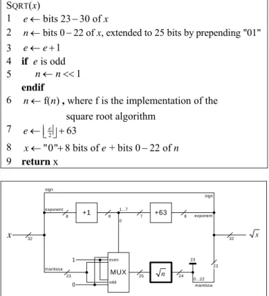
SQRT(x)
1 e←bits 23 30 of − x
2 n←bits 0 22 of , extended to 25 bits by prepending "01"− x 3 e← +e 1
4 if e is odd
5 n← <<n 1
endif
6 n←f( )n , where f is the implementation of the
square root algorithm 7 e←⎢ ⎥2e +63 ⎣ ⎦ 8 x←"0" 8 bits of + bits 0 22 of + e − n 9 return x 32 +1 exponent MUX +63 8 mantissa 23 1 0 even odd 0 25 1...7 7 8 23 0...22 32 sign sign exponent mantissa 8 24 23 n x x
Figure 1. Hardware to implement a generic square root algorithm on
IEEE 754 floats. An actual implementation of this would have to handle negative, denormalized, infinite, and NaN inputs, but is not shown here.
In hardware, this can be visualized by Figure 1. Note that optimizing this floating point wrapper is not relevant to this study; it is simply important that we use the same wrapper when comparing the two algorithms.
II. ALGORITHMS
The algorithms presented in this paper are different imple-mentations of fundamentally the same concept.
2 2
( ) 2
n= a±b =a ± ab b+ 2
where a is an estimate of the square root, and b is a trial offset that is a power of two and is successively halved until the de-sired accuracy is reached. Therefore, each iteration provides us with an additional bit of accuracy.
This is in contrast to the standard Newtonian algorithms, which converge much faster but involve more complex (time-consuming) calculations.
A. Hain’s Algorithm
Hain’s algorithm consists of determining the result bit by bit, by beginning with a trial offset, b, of the most-significant bit of the output. If 2p
x= ×n , then the initial trial offset
is 2
0 2
p
b = ⎢ ⎥⎣ ⎦. As each bit is considered, the trial offset is halved, so that 22
p
i i
b = ⎢ ⎥−⎣ ⎦ .
At each iteration, the trial offset, , is added to the root es-timate, , and if
i
b
i
i
bmust be one, so is added to our result.
2 if ( ) otherwise i i i i i a x a b a a b ⎧ < + ⎪ = ⎨ + ⎪⎩ i
Note that the comparison can be written a different way:
2 2 2 2 2 2 2 2 2 ( ) 2 2 2 i i i i i i i i i i i i i i i x a b i x a a b b x a a b b x a a b b b b < + < + + − < + − + <
Hain capitalizes on the fact that that the two sides of the inequality are easier to initialize and update from iteration to iteration than they are to calculate at each iteration. If we call these variables si and respectively, then ti si+1 is calculated as: 2 1 1 2 1 2 2 1 2 2 2 1 , if ( 2 ) , otherwise 4 , if 4( ), otherwise i i i i i i i i i i i i i i i i i x a s b x a s t b x a a b b b s s t s t + + + + + − = ⎧ − < ⎪ ⎪ = ⎨ − + + ⎪ ⎪⎩ < ⎧ = ⎨ − ⎩
and ti+1 is calculated as:
2 1 1 1 1 2 1 2 2 1 2 2 2 1 2 , if ( 2 ) , otherwise 2 1 2( 1) 1, if 2 3 2( 1) 1, otherwise i i i i i i i i i i i i i i i i i i i i a b b t b x a s t b x a a b b b t t s t t t + + + + + + + + = ⎧ − < ⎪ ⎪ = ⎨ − + + ⎪ ⎪⎩ − = − + < ⎧ = ⎨ − = + + ⎩
Putting these concepts together into an algorithm, we have Hain’s algorithm, SQRT_HAIN.
SQRT_HAIN(n) [n is a p-bit integer]
1 s←0 2 a←0 3 t←1 4 for i=1 to 2 p 5 2 2 4 p , 4 mod 2 p n s← s+⎢⎣ − ⎥⎦ n← n [implemented as 2 LSH n into s 6 if s<t 7 t← −t 1 8 a←2a [implemented as LSH 0 into a] else 9 s← −s t 10 t← +t 1 11 a←2a+1[implemented as LSH 1 into a] end if 12 t←2t+1[implemented as LSH 1 into t] next i 13 return a
1) Conversion To IEEE 754 Floats
Conversion of SQRT_HAIN to handle floating point numbers
is trivial. Although Hain’s algorithm terminates after 2p
itera-tions, since the integer square root of an integer has half as many bits as the input, the principles of the algorithm hold for nonintegers. That is, we can continue Hain’s algorithm to as many bits of precision as desired so long as we know where to place the decimal point when we are done. In this implemen-tation, however, this is easy, since the input is a number be-tween 1 and 4, the result is bebe-tween 1 and 2 (which is one bit less than the input, which is why the hardware implementation in Figure 2 only contains 24 bits in the output), so we know the decimal point will be between the first and second bits. Of course, after the first 2p iterations, the two bits we left-shift off
n in step 5 will be zeroes.
Finally, since we know that the first bit of the result will be 1, we can short-circuit the first loop iteration by initializing our variables correctly in steps 1–3. The resulting algorithm for implementation in our IEEE 754 float square root proces-sor is as follows. Note that subscripts indicate bits of the vari-able, and all registers are 24 bits long. (Although the input n is 25 bits long, it is immediately cut down to 23 bits, so, in fact, only a 23-bit register is required to hold n.)
SQRT_HAIN(n) [n is a 25-bit fixed point number 1≤ <n 4] 1 s←(n>>23)−1
2 n← <<n 2
3 a←1
4 t←5
5 while a23≠1[will loop 23 times]
6 s←(s<<2) (+ n>>23) 7 n← <<n 2 8 if s<t 9 t← −t 1 10 else 1 a← <<a 11 s← −s t 12 t← +t 1 13 end if ( 1) a← a<< +1 14 loop ( 1) t← << +t 1 15 s←s2 16 if s≥t 17 end if 1 a← +a 18 return a
Steps 15–17 of the loop are to determine whether to round down or up, and are a partial repetition of the loop. No addi-tional hardware is required to perform this check, though an additional adder is required for step 17. Mathematical proper-ties of square roots are such that any square root with a one in this 25th position is irrational, so we don’t have to worry about
whether to round up or down (IEEE 754 specifies that such rounding would be toward the even number, but since the number is irrational, we are guaranteed to not to have a result exactly halfway between two IEEE 754 numbers).
B. Freire’s Algorithm
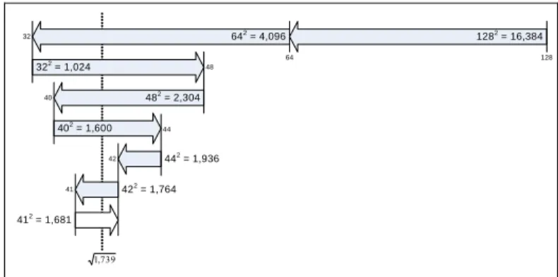
Freire’s algorithm for finding square roots is based on the idea that the list of all possible square roots for a particular preci-sion is finite and ordered, and therefore a binary search can be performed on the range to find the matching square root value. The list is ordered because square roots are monotonically increasing (for every x>y, x> y), and it is finite, be-cause there are a finite number of numbers that can be ex-pressed with the p bits used by a computer to store numbers. The algorithm is described by the following pseudocode, and illustrated in Figure 2. 1282 = 16,384 422 = 1,764 642 = 4,096 322 = 1,024 482 = 2,304 402 = 1,600 442 = 1,936 412 = 1,681 32 48 40 44 42 41 128 64 739 , 1
Figure 2. Finding the square root of 1,739 using Freire’s binomial search algorithm. In the figure, p = 16, so there are 216 = 65,536 possible numbers in
the number system (0–65,535). The maximum square root is therefore 216 – 1
< 256, so the initial test value is 256 ÷ 2 = 128. The increment begins as half the initial test value, and is halved with each iteration: 64, 32, 16, 8, etc. Since 1282 > 1,739 the increment is subtracted from the test value, and then tested
again. At each iteration, if the square of the test value is greater than 1,739, then the increment is subtracted from the test value; if the square is less, then the increment is added to the test value. After seven iterations, we have deter-mined that the answer lies somewhere between 41 and 42, and we have run out of bits for our precision. To finally determine which one to choose, we could
perform one more iteration to see how 41.52 compares to 1,739, but, in fact,
there is some faster mathematics that can be performed on some of the residual variables to determine which one to choose. In this example, 42 is chosen.
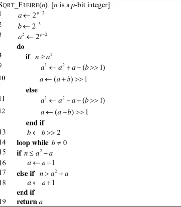
SQRT_FREIRE(n) [n is a p-bit integer]
1 b2 ←2p−2 2 22 1 p a← − 3 2 1 p i← − 4 b←a 5 a2←b2 do 6 b2 ←b2÷4[implemented as b2 >>2] 7 b← ÷b 2 [implemented as b>>1] 8 if 2 n≥a 9 2 2 2i a ←a + × +a b2 [a×2i implemented as a<<i] 10 a← +a b else 11 a2 ←a2− × +a 2i b2 12 a← −a b end if 13 i← −i 1 14 loop while i>0 15 if n≤a2−a 16 a← −a 1 17 else if 2 n>a +a 18 a← +a 1 end if 19 return a
In the algorithm, a represents the result, which is iteratively improved by adding or subtracting the delta b, which is halved each iteration. Instead of squaring a each iteration to compare to n (which involves a costly multiplication), 2 is kept in its
own variable and updated according to the formula
2 2 2
(a ±b )=a ±2ab b+ 2
2 .
The is known at the beginning ( ), and as b is halved each iteration (line 7), is quartered (line 6), both of which can be accomplished with bitwise right-shifts. Fur-thermore, the apparent multiplication of 2ab can be eliminated by realizing that , so , which can again be implemented by a bitwise shift of i bits to the left (lines 9 and 11). Therefore, each iteration of the loop requires three bit-wise shift operations, four additions or subtractions, and two comparisons (one of which is the comparison of i to 0), but no multiplications. 2 b 2p−2 2 b 1 2i b= − 2ab= ×a i
Freire actually does propose a slight improvement to the al-gorithm shown, based on the observation that i is really only used to shift a left each iteration to effect the 2ab multiplica-tion. Since i begins at 2p−1 and decreases down to 0, we can instead begin a shifted left 2p−1 (i.e., 22 1 22 1 2 2
p p
p
a← − ⋅ − = − ) and shift it right one bit each iteration. Now b, which was being added to or subtracted from a each iteration also needs to be shifted left by the same amount, and instead of right-shifting it one bit each iteration, it is right-shifted two bits. Now with b being right-shifted two bits every iteration, it is only one bit-shift away from the old , so we no longer have to keep track of that value as well. The improved algorithm becomes:
2 b
SQRT_FREIRE(n) [n is a p-bit integer]
1 a←2p−2 2 b←2−3 3 a2 ←2p−2 do 4 if 2 n≥a 9 2 2 ( 1 a ←a + +a b>> ) 10 else ( ) a← a+b >>1 11 a2 ←a2− +a (b>>1) 12 end if ( ) a← a b− >>1 13 b← >>b 2 14 loop while b≠0 15 if n≤a2−a 16 a← −a 1 17 else if n>a2+a 18 end if 1 a← +a 19 return a
This is the algorithm Freire converted to handle floating point numbers.
1) Conversion to floating Point
Freire’s algorithm as shown takes a p-bit number and
re-turns its 2p-bit square root. This works for integers because
the integer square root of an integer has half as many bits as the input. However, in floating point, we want the output to have the same number of bits as the input. This will require us to have twice as many iterations through the loop and dou-ble-length registers to hold intermediate values. To obtain the 24-bit output, we must start with a 48-bit input, so we would begin by shifting the 25-bit input left 23 bits into a 48-bit reg-ister.
As with Hain’s algorithm, since we know that the first bit is going to be one, we know the result of the first comparison, which we can short-circuit by initializing the variables as if the first loop iteration has already been completed. The ini-tializations in steps 1–3 can be replaced by respectively
3 44
a← , , and . The rest of the
al-gorithm remains exactly the same.
43
2
b← a2 ←944
III. PERFORMANCE AND PRECISION ANALYSIS
As these algorithms are intended to be implemented in hardware, an analysis of their performance must take into ac-count their hardware implementation. Precision must also be exact in order for the algorithms to be considered accurate enough for most processors today. Fortunately, as we shall see, both algorithms produce the full 24-bit accuracy in order to produce the closest possible approximation in 32-bit IEEE-754 floats.
A. Hain’s Algorithm
From a performance perspective, we can implement Hain’s algorithm in hardware similar to Figure 4. It is clear from the hardware implementation that Hain’s loop requires only the time required to perform a subtraction and a multiplex, and lock the results into the registers. Even the subtraction can be short-circuited, however, once the result is determined to be negative, since the actual result will not be used in that case.
s a t n MUX SUB ADD MUX b0...21 << 2 <<2 neg +1 b0 = 0 b0...22 <<1 b0 <<1 b0 = 1 –1 24 23 24 22 2 22 24 24 24 24 24 24 23 23 24 23 b0...22 1 24 n n b0...22 b23...24 1 5 <<1
Initialization Loop Termination
Figure 3. Hardware to implement Hain’s square root algorithm. All registers are 24 bits long. Bit shifts can be hardwired. Loop terminates after 23 iterations, when a23 = 1.
The loop repeats p−1, or ( )Θ p , times. The loop initializa-tion and terminainitializa-tion steps require only a subtracinitializa-tion (initiali-zation) and addition (termination). Even these operations can be implemented with half-adders, since they are only adding and subtracting one.
We can therefore calculate the running time of Hain’s algo-rithm by the following formula:
( ) ( 1)( )
( 1) ( 1) [assuming ]
Hain sub sub mux add
add mux sub add
T p t p t t t
p t p t t t
= + − + +
= + + − =
This indicates that Hain’s algorithm is very fast. For large enough p, traditional Newtonian methods will outperform, since they take , though their constants will be sig-nificantly higher.
(log )p
Θ
The mathematical basis of Hain’s algorithm indicates that it should produce l + 1 bits of precision, where l is the number of loop iterations. Since the loop iterates times, we end up with a full p bits of precision, as required by IEEE 754. Hain’s final addition is due to the fact that the bit of the result may be a one, in which case the result must be rounded up. There should be no issues with IEEE rounding (which require that a result halfway between two p-bit floats be rounded toward the even number), since all p-bit numbers with square roots of at least p significant bits are irrational. This precision is tested in the next section.
1 p−
( 1)th
p+
B. Freire’s Algorithm
Freire’s algorithm can be implemented in hardware similar to Figure 4. In contrast to Hain’s algorithm, Freire’s main loop has three layers of calculations. Furthermore his calcula-tions are performed in twice the precision of Hain’s, so in addition to the additional hardware and wires required to cal-culate and carry the extra bits, the additions and subtractions will take about 22% longer (best-case assumption, assuming carry-lookahead adders; if ripple-carry adders are used, then the time will double; and if carry-skip or carry-select adders are used, additions will take about 41% longer).
Figure 4. Hardware to implement Freire’s square root algorithm. Dia-gram taken directly from Freire [1]. In his diaDia-gram, register EAX is n, EBX is a, ECX is b, and EDX is a2. All registers are 48 bits long. Loop terminates
after 22 iterations, when b = 0. Omitted from Freire’s diagram, however, are the calculations that must be performed after the loop terminates to handle rounding. The termination calculations are about as complicated as a single loop iteration and require additional hardware.
Freire’s run-time can be calculated as follows:
)
( ) ( 2)(2 ) ( 2 ) [assuming ]
(2 3)
Freire add mux add mux sub add
add mux T p p t t t t t t p t p t ′ ′ ′ ′ = − + + + = ′ = − + ⋅
If we assume that tadd′ ≈1.22tadd, and that , then Freire’s algorithm takes about 2.44 times as long as Hain’s.
mux add
t t
Freire’s algorithm is every bit as precise as Hain’s. Its post-loop processing essentially simulates another iteration of the loop to determine whether one needs to be added to or sub-tracted from the result. This will be tested in the next section. A final issue worth considering is the space consumed by Freire’s algorithm compared to Hain’s. It is clear that Freire’s would occupy at least twice as much space as Hain’s due to the size doubling of the registers. Furthermore, Freire’s ap-proach requires more arithmetic and logical components, so it is not unreasonable to presume that Freire’s algorithm would take 2.5 or 3 times the amount of space on a chip as Hain’s.
IV. EXPERIMENTAL COMPARISON
A program1 was written to test the precision of these
algo-rithms, to determine whether the assertions made in the previ-ous section are valid. Although performance was also meas-ured and the results presented here, performance tests of the algorithms written in software are only of use as evidence for or against rather than proof of the performance conclusions made in the previous section.
A. Methodology
The two algorithms were implemented using the same float-ing-point-to-fixed-point conversion so that the only difference would be in the way the two algorithms compute the square root. The two functions were then used to compute the square root for every 32-bit IEEE-754 floating point number between one and four (inclusive of one, exclusive of four). These lim-its were chosen because they include every possible 25-bit fixed point mantissa sent to the square root functions for all normalized floats from 2–126 to 2128. Expanding the limits
would change only the exponent without changing the man-tissa.
Precision was checked by squaring the result and compar-ing the square to the input value. If the comparison showed that the square of the calculated root was smaller than the in-put, then the result had the smallest possible quantum (2–23)
added to it to see if the resulting square would be closer to the input. If it were not, then the function had returned the closest possible 32-bit IEEE-754 number to the square root. The op-posite was done if the square of the calculated root was larger than the input (i.e., a quantum was subtracted from the result and the square compared to the input).
As a sanity check, Hain’s square root algorithm was also implemented in microcode on a 2 slice/16-bit Texas Instru-ments 74AS-EVM-16 processor using 32-bit even-odd regis-ter pairs. Friere’s algorithm was not implemented, but rather Hain’s square root operation was compared to a microcoded
floating point divide operation on the same architecture. B. Results
Both functions calculated all 16,777,216 square roots accu-rately in every bit.
The programmed implementation of Hain’s algorithm proved to be about 86% faster than Freire’s. However, as mentioned earlier, the relative timings would depend on the specific hardware implementations, where some of the microoperations operations can be executed in parallel.
The microcoded comparisons showed that Hain’s floating point square root implementation took only 89% more clock cycles than the floating point divide operation. That is, it ran slightly faster than two floating point divides. Again, this should be regarded as indicative only, since no architectural optimizations were performed. It is conceivable, however, that any optimizations on one operation could be applied to the other, so that the relative timings may, in fact, be a good indi-cator.
V. CONCLUSIONS
While they are equivalent in precision, Hain’s algorithm is superior to Freire’s both in hardware cost and time. Although Hain’s algorithm converges on its result in O(p) time versus other methods that converge in O(log p) time, it is likely that Hain’s algorithm is superior for small p (say 32, or 64), and further comparisons could be performed to determine the break-even point where conventional methods begin to out-perform Hain.
REFERENCES
[1] Freire, P. http://www.pedrofreire.com/sqrt. 2002.
[2] Goldberg, D. “Computer Arithmetic”. Xerox Palo Alto Research Cen-ter, 2003. Published as App. H in Computer Architecture: A Quantita-tive Approach, Third Edition by Hennessy, J.L. and Patterson, D.A., Morgan Kaufmann, 2002. Available at http://books.elsevier.com/com-panions/1558605967/appendices/1558605967-appendix-h.pdf. [3] Hain, T. “Floating Point Arithmetic Processor”. Internal Report, CIS,
University of South Alabama, Mobile, AL 36688, 1989.
[4] Jovanović, B., Damnjanović, M.: “Digital Systems for Square Root Computation”, Zbornik Radova XLVI Konferencije Etran, Herceg Novi, Montenegro, June 2003, Vol 1, pp. 68-71.
[5] R. Goldschmidt, Application of division by convergence, Master’s the-sis, MIT, June,1964.
[6] Sun Microsystems, Inc, “Numerical Computation Guide”, http://docs.sun.com/source/806-3568/ncgTOC.html.