and Setup Guide
(SUCH AS TRANSLATION, TRANSFORMATION, OR ADAPTATION) WITHOUT THE EXPRESS WRITTEN PERMISSION OF CITRIX SYSTEMS, INC.
ALTHOUGH THE MATERIAL PRESENTED IN THIS DOCUMENT IS BELIEVED TO BE ACCURATE, IT IS PRESENTED WITHOUT WARRANTY OF ANY KIND, EXPRESS OR IMPLIED. USERS MUST TAKE ALL RESPONSIBILITY FOR THE USE OR APPLICATION OF THE PRODUCT(S) DESCRIBED IN THIS MANUAL. CITRIX SYSTEMS, INC. OR ITS SUPPLIERS DO NOT ASSUME ANY LIABILITY THAT MAY OCCUR DUE TO THE USE OR APPLICATION OF THE PRODUCT(S) DESCRIBED IN THIS DOCUMENT. INFORMATION IN THIS DOCUMENT IS SUBJECT TO CHANGE WITHOUT NOTICE. COMPANIES, NAMES, AND DATA USED IN EXAMPLES ARE FICTITIOUS UNLESS OTHERWISE NOTED.
The following information is for FCC compliance of Class A devices: This equipment has been tested and found to comply with the limits for a Class A digital device, pursuant to part 15 of the FCC rules. These limits are designed to provide reasonable protection against harmful interference when the equipment is operated in a commercial
environment. This equipment generates, uses, and can radiate radio-frequency energy and, if not installed and used in accordance with the instruction manual, may cause harmful interference to radio communications. Operation of this equipment in a residential area is likely to cause harmful interference, in which case users will be required to correct the interference at their own expense.
Modifying the equipment without Citrix' written authorization may result in the equipment no longer complying with FCC requirements for Class A digital devices. In that event, your right to use the equipment may be limited by FCC
regulations, and you may be required to correct any interference to radio or television communications at your own expense.
You can determine whether your equipment is causing interference by turning it off. If the interference stops, it was probably caused by the NetScaler Request Switch™ 9000 Series equipment. If the NetScaler equipment causes
interference, try to correct the interference by using one or more of the following measures: Move the NetScaler equipment to one side or the other of your equipment.
Move the NetScaler equipment farther away from your equipment.
Plug the NetScaler equipment into an outlet on a different circuit from your equipment. (Make sure the NetScaler equipment and your equipment are on circuits controlled by different circuit breakers or fuses.)
Modifications to this product not authorized by Citrix Systems, Inc., could void the FCC approval and negate your authority to operate the product.
BroadCom is a registered trademark of BroadCom Corporation. Fast Ramp, NetScaler, and NetScaler Request Switch are trademarks of Citrix Systems, Inc. Linux is a registered trademark of Linus Torvalds. Internet Explorer, Microsoft, PowerPoint, Windows and Windows product names such as Windows NT are trademarks or registered trademarks of the Microsoft Corporation. NetScape is a registered trademark of Netscape Communications Corporation. Red Hat is a trademark of Red Hat, Inc. Sun and Sun Microsystems are registered trademarks of Sun Microsystems, Inc. Other brand and product names may be registered trademarks or trademarks of their respective holders.
Software covered by the following third party copyrights may be included with this product and will also be subject to the software license agreement: Copyright 1998 © Carnegie Mellon University. All rights reserved. Copyright © David L.
Mills 1993, 1994. Copyright © 1992, 1993, 1994, 1997 Henry Spencer. Copyright © Jean-loup Gailly and Mark Adler.
Copyright © 1999, 2000 by Jef Poskanzer. All rights reserved. Copyright © Markus Friedl, Theo de Raadt, Niels Provos,
Dug Song, Aaron Campbell, Damien Miller, Kevin Steves. All rights reserved. Copyright © 1982, 1985, 1986,
1988-1991, 1993 Regents of the University of California. All rights reserved. Copyright © 1995 Tatu Ylonen, Espoo,
Finland. All rights reserved. Copyright © UNIX System Laboratories, Inc. Copyright © 2001 Mark R V Murray. Copyright
1995-1998 © Eric Young. Copyright © 1995,1996,1997,1998. Lars Fenneberg. Copyright © 1992. Livingston
Enterprises, Inc. Copyright © 1992, 1993, 1994, 1995. The Regents of the University of Michigan and Merit Network,
Inc. Copyright © 1991-2, RSA Data Security, Inc. Created 1991. Copyright © 1998 Juniper Networks, Inc. All rights
reserved. Copyright © 2001, 2002 Networks Associates Technology, Inc. All rights reserved. Copyright (c) 2002
Networks Associates Technology, Inc. Copyright 1999-2001© The Open LDAP Foundation. All Rights Reserved.
Copyright © 1999 Andrzej Bialecki. All rights reserved. Copyright © 2000 The Apache Software Foundation. All rights
reserved. Copyright (C) 2001-2003 Robert A. van Engelen, Genivia inc. All Rights Reserved. Copyright (c) 1997-2004 University of Cambridge. All rights reserved. Copyright (c) 1995. David Greenman. Copyright (c) 2001 Jonathan Lemon. All rights reserved. Copyright (c) 1997, 1998, 1999. Bill Paul. All rights reserved. Copyright (c) 1994-1997 Matt Thomas.
All rights reserved. Last Updated: March 2010
Preface...9
Formatting Conventions for NetScaler Documentation . . . .9
Documentation Available on the NetScaler Appliance . . . 10
Getting Service and Support . . . 11
NetScaler Documentation Feedback . . . .11
1 Introduction to the Hardware Platforms ...13
Common Hardware Components . . . 14
LCD Display. . . 14
Ports . . . 18
RS232 Serial Port. . . .19
Copper Ethernet Ports. . . .19
Management Ports. . . .19
SFP Ports. . . 19
SFP+ and XFP Ports. . . .19
LED Port-Status Indicators. . . 19
Power Supply . . . .22
CompactFlash Card. . . .23
Solid-State Drive. . . 23
Hard Disk Drive. . . 23
Hardware Platforms . . . .23 Citrix NetScaler 7000. . . 23 Citrix NetScaler 9010. . . 24 Citrix NetScaler 10010. . . .26 Citrix NetScaler 12000. . . .28 Citrix NetScaler MPX 5500. . . 30
Citrix NetScaler MPX 7500 and MPX 9500. . . 31
Citrix NetScaler MPX 9700, MPX 10500, MPX 12500, and MPX 15500. . . .33
Citrix NetScaler MPX 17500, MPX 19500, and MPX 21500. . . .35
Citrix NetScaler MPX 15000. . . .36
Citrix NetScaler MPX 17000. . . .37
2 Preparing for Installation ... 43
Unpacking the NetScaler Appliance . . . .44
Preparing the Site and Rack . . . .44
Site Requirements. . . .45
Rack Requirements. . . .45
Cautions and Warnings. . . .46
Electrical Safety Precautions. . . .46
Appliance Precautions. . . .47
Rack Precautions. . . .47
3 Installing the Hardware...49
Rack Mounting the Appliance . . . .50
To remove the inner rails from the rail assembly. . . .50
To attach the inner rails to the appliance. . . .51
To install the rack rails. . . .51
To install the appliance in the rack. . . .52
Installing and Removing SFP Transceivers . . . .52
To install an SFP transceiver. . . .53
To remove an SFP transceiver. . . .53
Installing and Removing XFP and SFP+ Transceivers . . . .54
To install an XFP/SFP+ transceiver. . . .54
To remove an XFP/SFP+ transceiver. . . .55
Connecting the Cables . . . .56
Connecting the Ethernet Cables. . . .56
To connect an Ethernet cable to a 10/100/1000BASE-T port or 1-gigabit SFP copper transceiver. . . .56
To connect the Ethernet cable to an SFP fiber, SFP+, or XFP transceiver. . . .57
Connecting the Console Cable. . . .57
To connect the console cable to a computer or terminal. . . .57
Connecting the Power Cable. . . .58
To connect the appliance to the power source. . . .58
Turning on the Appliance. . . .59
To turn on the appliance. . . .59
4 Initial Configuration ...61
Configuring the Initial Settings by Using the NetScaler Serial Console . . . .62
To configure initial settings by using a serial console. . . .62
To configure initial settings by using the Setup Wizard. . . .64
Using DHCP for Initial Access . . . .65
Prerequisites. . . .65
To configure a Linux/Unix DHCP server for the NetScaler. . . .66
Implementing an Initial NetScaler Configuration from a Remote Computer. . . .66
Example. . . .67
Using DHCP When a Configuration File is Present. . . .67
Accessing a NetScaler by Using SSH keys and No Password . . . .68
To generate the public/private key on a Linux client. . . .68
To copy the public key to the remote NetScaler . . . .69
To set up secure shell access with public key encryption on the NetScaler. . . .69
To verify secure shell access with public key encryption on the NetScaler. . . .69
Learn about the NetScaler® collection of documentation, including information about
support options and ways to send us feedback.
In this preface:
w Formatting Conventions for NetScaler Documentation
w Documentation Available on the NetScaler Appliance
w Getting Service and Support
w NetScaler Documentation Feedback
For information about new features and enhancements for this release, see the Citrix NetScaler 9.1 Release Notes at http://edocs.citrix.com/.
Formatting Conventions for NetScaler
Documentation
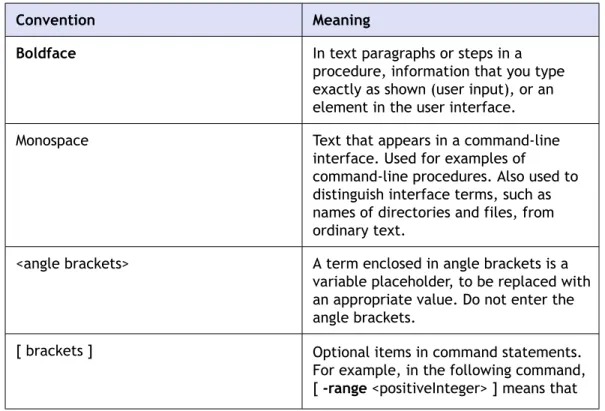
The NetScaler documentation uses the following formatting conventions.
Table 1: Formatting Conventions
Convention Meaning
Boldface In text paragraphs or steps in a
procedure, information that you type exactly as shown (user input), or an element in the user interface. Monospace Text that appears in a command-line
interface. Used for examples of
command-line procedures. Also used to distinguish interface terms, such as names of directories and files, from ordinary text.
<angle brackets> A term enclosed in angle brackets is a variable placeholder, to be replaced with an appropriate value. Do not enter the angle brackets.
[ brackets ] Optional items in command statements. For example, in the following command, [ -range <positiveInteger> ] means that
Convention Meaning
you have the option of entering a range, but it is not required:
add lb vserver <name> <serviceType>
<IPAddress> <port> [ -range <positiveInteger>]
Do not type the brackets themselves. | (vertical bar) A separator between options in braces or
brackets in command statements. For example, the following indicates that you choose one of the following load balancing methods: <lbMethod> = ( ROUNDROBIN | LEASTCONNECTION | LEASTRESPONSETIME | URLHASH | DOMAINHASH | DESTINATIONIPHASH | SOURCEIPHASH | SRCIPDESTIPHASH | LEASTBANDWIDTH | LEASTPACKETS | TOKEN | SRCIPSRCPORTHASH | LRTM | CALLIDHASH | CUSTOMLOAD )
… (ellipsis) You can repeat the previous item or items in command statements. For example, /route:<DeviceName>[ ,…] means you can type additional
<DeviceNames> separated by commas.
Documentation Available on the NetScaler
Appliance
A complete set of NetScaler documentation (PDF format) is available on the
Documentation tab of your NetScaler appliance and from http://support.citrix.com/. (Most of the documents require Adobe Reader, available at http://adobe.com/.)
To view the documentation
1. From a web browser, log on to the NetScaler. 2. Click the Documentation tab.
3. To view a short description of each document, hover your cursor over the title. To open a document, click the title.
Getting Service and Support
Citrix offers a variety of resources for support with your Citrix environment, including the following:
w The Knowledge Center is a self-service, web-based technical support database that contains thousands of technical solutions, including access to the latest hotfixes, service packs, and security bulletins.
w Technical Support Programs for both software support and appliance maintenance are available at a variety of support levels.
w The Subscription Advantage program is a one-year membership that gives you an easy way to stay current with the latest product version upgrades and enhancements.
w Citrix Education provides official training and certification programs on virtually all Citrix products and technologies.
For more information about Citrix services and support, see the Citrix Systems Support web site at http://www.citrix.com/lang/English/support.asp.
You can also participate in and follow technical discussions offered by the experts on various Citrix products at the following sites:
w http://community.citrix.com w http://twitter.com/citrixsupport
NetScaler Documentation Feedback
You are encouraged to provide feedback and suggestions so that we can enhance the documentation. You can send email to [email protected]. In the subject line, specify "Documentation Feedback." Please include the title of the guide and the page number in the email message.
You can also provide feedback through the Knowledge Center at http:// support.citrix.com/.
To provide feedback at the Knowledge Center home page
1. Go to the Knowledge Center home page at http://support.citrix.com/.
2. On the Knowledge Center home page, under Products, expand NetScaler, and then click the NetScaler release for which you want to provide feedback.
3. On the Documentation tab, click the guide name, and then click Article Feedback. 4. On the Documentation Feedback page, complete the form, and then click Submit.
Introduction to the Hardware Platforms
Topics:
• Common Hardware Components • Hardware Platforms • Summary of Hardware SpecificationsThe NetScaler hardware platforms range from the single processor MPX 5500 and 7000 platforms to the high-capacity, fault-tolerant MPX 17500/19500/21500 hardware platforms. The various NetScaler hardware platforms are similar in that they use the same types of components, but different models provide different hardware capabilities. All NetScaler
hardware platforms support the NetScaler operating system. Some of the hardware platforms are available as dedicated application firewall appliances or secure application access appliances.
Common Hardware Components
Each platform has front panel and back panel hardware components. The front panel has an LCD display and an RS232 serial console port. The number, type, and location of ports—copper Ethernet, copper and fiber SPF, SFP+, and XFP—vary by hardware
platform. The back panel provides access to the power supply, fan, CompactFlash card, solid-state drive, and hard disk drive.
LCD Display
The LCD display on the front of every appliance displays messages about the current operating status of the appliance. These messages communicate whether your appliance has started properly and is operating normally. If the appliance is not operating normally, the LCD displays troubleshooting messages.
The LCD displays real-time statistics, diagnostic information, and active alerts. The dimensions of the LCD limit the display to two lines of 16 characters each, causing the displayed information to flow through a sequence of screens. Each screen shows information about a specific function.
The LCD has a neon backlight. Normally, the backlight glows steadily. When there is an active alert, it blinks rapidly. If the alert information exceeds the LCD screen size, the backlight blinks at the beginning of each display screen. When the appliance shuts down, the backlight remains on for one minute and then automatically turns off. There are nine types of display screens on the LCD display. The first two screens in the following list, the booting screen and the startup screen, appear when your appliance is starting up. The other screens, except the out-of-service screen, can appear while the appliance is operating. They show configuration information, alerts, HTTP
information, network traffic information, CPU load information, and port information for your appliance.
Booting Screen.
The booting screen is displayed immediately after the appliance is turned on. The first line displays the hardware platform, as shown in the following figure.
Figure 1-1: LCD booting screen
The newer MPX appliances display NSMPX followed by the platform number in the first line. For example, the MPX 7500/9500 appliances display NSMPX-7500. To view the model number, at the NetScaler command line, type show license. Scroll to the end of the command output to view the model number.
The startup screen is displayed for a few seconds after the appliance successfully begins operation. The first line displays the hardware platform, and the second line displays the software version and build number, as shown in the following figure.
Figure 1-2: LCD startup screen
Out-of-Service Screen.
The out-of-service screen is displayed when the appliance has undergone a controlled shutdown, as shown in the following figure.
Figure 1-3: LCD out-of-service screen
Configuration Screen.
The first line displays the appliance status (STA, PRI, or SEC) and uptime. STA indicates that the appliance is in standalone mode, PRI indicates that the appliance is a primary node in a high availability (HA) pair, and SEC indicates that the appliance is a secondary node in an HA pair. Appliance uptime is displayed in HH:MM format. The second line displays the IP address of the appliance, as shown in the following figure.
Figure 1-4: LCD configuration screen
Alert Screen.
An unknown alert is displayed differently than a known alert, as shown in the
following figures. In either case, the first line displays the appliance status (STA, PRI, or SEC). STA indicates that the appliance is in standalone mode, PRI indicates that the appliance is a primary node in a high availability (HA) pair, and SEC indicates that the appliance is a secondary node in an HA pair. The second line displays the IP address of the appliance.
Figure 1-6: LCD unknown alert screen
HTTP Statistics Screen.
The first line displays the rate of HTTP GETS per second. The second line displays the rate of HTTP POSTS per second, as shown in the following figure.
Figure 1-7: LCD HTTP statistics screen
Network Traffic Statistics Screen.
The first line displays the rate at which data is received, in megabits per second. The second line displays the rate of data transmission, in megabits per second, as shown in the following figure.
Figure 1-8: LCD network traffic statistics screen
CPU Load, Memory, and Connections Screen.
The first line displays CPU utilization and memory utilization as percentages. The second line displays the ratio of the number of server connections to the number of client connections.
Note: If the number of server or client connections exceeds 99,999, the number is displayed in thousands, indicated by the letter K.
Figure 1-9: LCD CPU load, memory, and connections screen
Port Information Screen.
The S row displays port speed, flow control, and duplex information. The R row displays megabits received per second on the interface. The first port in each row is the management port.
Figure 1-10: Port information for an 8-port appliance
Figure 1-11: Port Information for a 10-port appliance
The following table defines the various abbreviations and symbols that appear in the S row of the port information screen.
Table 1-1: Port abbreviations and symbols for S row
S Row Abbreviation/Symbol Indicates
A rate of 10 megabits per second, full duplex mode, and flow control OFF. A rate of 100 megabits per second, full duplex mode, and flow control OFF. A rate of 1 gigabit per second, full duplex mode, and flow control OFF. A rate of 10 gigabits per second, full duplex mode, and flow control OFF. A disconnected port.
Note: The R row does not display an abbreviation or symbol for a
disconnected port.
Receive flow control regardless of speed or duplex mode.
Transmit flow control regardless of speed or duplex mode.
Receive and transmit flow control regardless of speed or duplex mode.
S Row Abbreviation/Symbol Indicates
A rate of 10 megabits per second, half duplex mode, and flow control OFF. A rate of 100 megabits per second, half duplex mode, and flow control OFF. A rate of 1 gigabit per second, half duplex mode, and flow control OFF. The following table defines the various abbreviations and symbols that appear in the R row of the port information screen.
Table 1-2: Port abbreviations and symbols for R row
R Row Abbreviation/Symbol Indicates
The port is disabled.
Receive speed is approximately 10% of line speed.
Receive speed is 50% of line speed.
Receive speed is 75% of line speed. Receive speed is 100% of line speed.
Ports
Ports are used to connect the appliance to external devices. NetScaler appliances support RS232 serial ports, 10/100/1000Base-T copper Ethernet ports, 1-gigabit copper and fiber SFP ports, and 10-gigabit fiber SFP+ and XFP ports. All NetScaler appliances have a combination of some or all of these ports. For details on the type and number of ports available on your appliance, see the section describing that platform.
RS232 Serial Port
The RS232 serial console port on the front of each appliance provides a connection between the appliance and a computer, allowing direct access to the appliance for initial configuration or troubleshooting.
All hardware platforms ship with an appropriate serial cable used to connect your computer to the appliance. For instructions on connecting your computer to the appliance, see Installing the Hardware on page 49.
Copper Ethernet Ports
The copper Ethernet ports installed on many models of the appliance are standard RJ45 ports.
There are two types of copper Ethernet ports that may be installed on your appliance:
10/100BASE-T port
This type of port has a maximum transmission speed of 100 megabits per second (Mbps). Most platforms have at least one 10/100BASE-T port.
10/100/1000BASE-T port
This type of port has a maximum transmission speed of 1 gigabit per second, ten times faster than the other type of copper Ethernet port. Most platforms have at least one 10/100/1000Base-T port.
To connect any of these ports to your network, you plug one end of a standard Ethernet cable into the port and plug the other end into the appropriate network connector.
Management Ports
Management ports are standard copper Ethernet ports (RJ45) that are used for direct access to the appliance for system administration functions.
SFP Ports
An SFP port can operate at a speed of 1 gigabit per second. It accepts either a copper SFP transceiver for operation as a copper Ethernet port or a fiber SFP transceiver for operation as a fiberoptic port.
SFP+ and XFP Ports
The SFP+ and XFP ports are high-speed ports that can operate at speeds of 10 gigabits per second. You need a fiberoptic cable to connect to an SFP+ or XFP port. If the other end of the fiberoptic cable is attached to a 1GE SPF port, the 10GE SFP+ port will automatically negotiate to the speed of a 1GE SPF port.
LED Port-Status Indicators
Note: This section applies to the MPX 5500, MPX 7500/9500, MPX 9700/10500/12500/15500, and MPX 17500/19500/21500 appliances.
The port LEDs show whether the link is established and traffic is passing through the port. The following table describes the LED indicators for each port.There are two LED indicators for each port type.
Table 1-3: LED port-status indicators
Port Type LED Location LED Function LED Color LED Indicates
SFP+ (10 Gbps) Left Link/ Activity Off No link. Solid green Link is
established but no traffic is passing through the port. Blinking green Traffic is
passing through the port.
Right Speed Off No connection. Solid green Traffic rate of
10 gigabits per second. SFP (1 Gbps) Left Link/ Activity Off No link. Solid green Link is
established but no traffic is passing through the port. Blinking green Traffic is
passing through the port.
Right Speed Off No connection. Yellow Traffic rate of
1 gigabit per second. Ethernet
(RJ45)
Left Speed Off No connection or a rate of 10 megabits per second (Mbps).
Port Type LED Location LED Function LED Color LED Indicates
Green Traffic rate of 100 Mbps. Yellow Traffic rate of
1 gigabit per second. Right Link/ Activity Off No link. Solid green Link is
established but no traffic is passing through the port. Blinking green Traffic is
passing through the port. Management
(RJ45)
Left Speed Off No connection or a rate of 10 megabits per second (Mbps). Green Traffic rate of
100 Mbps. Amber Traffic rate of
1 gigabit per second. Right Link/ Activity Off No link. Solid yellow Link is
established but no traffic is passing through the port. Blinking yellow Traffic is
passing through the port.
Power Supply
Appliances are configured with either a single power supply or, for higher capacity fault tolerant models, a dual power supply configuration.
The appliance ships with a standard power cord that plugs into the appliance’s power supply and an NEMA 5-15 plug on the other end for connecting to the power outlet on the rack or in the wall.
For power-supply specifications, see Hardware Platforms on page 23 which describes the various platforms and includes a table summarizing the hardware specifications.
Note: If you suspect that a power-supply fan is not working, please see the
description of your platform. On some platforms, what appears to be the fan does not turn, and the actual fan turns only when necessary.
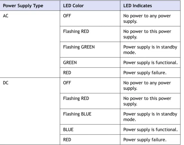
For each power supply, a bi-color LED indicator shows the condition of the power supply.
Table 1-4: LED Power Supply Indicators
Power Supply Type LED Color LED Indicates
AC OFF No power to any power
supply.
Flashing RED No power to this power supply.
Flashing GREEN Power supply is in standby mode.
GREEN Power supply is functional. RED Power supply failure.
DC OFF No power to any power
supply.
Flashing RED No power to this power supply.
Flashing BLUE Power supply is in standby mode.
BLUE Power supply is functional. RED Power supply failure.
CompactFlash Card
The CompactFlash card contains the operating system for all hardware platforms except for the MPX 17500/19500/21500. CompactFlash is mounted as /flash.
Solid-State Drive
The solid-state drive on only the MPX 17500/19500/21500 platform contains the operating system. It is mounted as /flash.
Hard Disk Drive
The hard disk drive contains logs and other data files on all hardware platforms. It is mounted as /var.
Hardware Platforms
The various NetScaler hardware platforms offer a wide range of features,
communication ports, and processing capacities. All the MPX platforms have multicore processors.
Citrix NetScaler 7000
The Citrix NetScaler 7000 appliance is a 1U appliance, with 1 single-core processor, and 1 gigabyte (GB) of memory.
Note: NetScaler 9.1 nCore release is not supported on this hardware platform.
The following figure shows the front panel of the 7000.
Figure 1-12: Citrix NetScaler 7000, front panel
The 7000 has the following ports:
w Six 10/100BASE-T copper Ethernet ports, named 1/1, 1/2, 1/3, 1/4, 1/5, and 1/6. Port 1/1 is the upper-left port, port 1/2 is the port beneath it, and the other 10/100BASE-T ports are named sequentially as you move from left to right, top to bottom.
w Two 10/100/1000BASE-T copper Ethernet ports, named 1/7 and 1/8. Port 1/7 is the upper port, and port 1/8 is the port beneath it.
w RS232 serial Console Port.
Note: The network port numbers on all appliances consist of two numbers separated by a forward slash. The first number is the port adapter slot number. The second number is the interface port number. Ports on appliances are numbered sequentially starting with 1.
The following figure shows the back panel of the 7000.
Figure 1-13: Citrix NetScaler 7000, back panel
The following components are visible on the back panel of the 7000:
w Removable Hard Disk Drive that is used to store user data.
w Appliance Reset Switch, which signals the 7000 to perform an orderly shutdown after saving all data.
w Removable CompactFlash Card that is used to store the operating system.
w Power Switch, which turns off power to the 7000 just as if you were to unplug it.
w Power Supply rated at 250 watts, 110-220 volts.
Citrix NetScaler 9010
The Citrix NetScaler 9010 appliance is a 2U appliance, with 1 single-core processor, and 2 GB of memory.
Note: NetScaler 9.1 nCore release is not supported on this hardware platform.
There are three models of the 9010: the copper Ethernet version, the fiber SFP (Small Form Factor Pluggable) version, and the FIPS (Federal Information Processing
Standards) version. The following figure shows the front panel of the 9010 model with copper Ethernet ports.
The following figure shows the front panel of the 9010 with fiber SFP ports.
Figure 1-15: Citrix NetScaler 9010 front panel, with SFP ports
Depending on the model, the following components are visible on the front panel of the 9010:
w RS232 serial Console Port.
w Network ports
• 9010, copper Ethernet model. Four copper Ethernet 10/100/1000BASE-T ports, numbered 1/1, 1/2, 1/3, and 1/4 from left to right.
• 9010, SFP model. Four SFP ports, numbered 1/1, 1/2, 1/3, and 1/4 from left to right. When facing the bezel, the upper LEDs to the left of each optical SFP port inset represent connectivity. They are lit and amber in color when active. The lower LEDs represent throughput. They are lit and green when active.
• 9010 FIPS model. Four ports, numbered 1/1, 1/2, 1/3, and 1/4 from left to right.
Note: The network port numbers on all appliances consist of two numbers separated by a forward slash. The first number is the port adapter slot number. The second number is the interface port number. Ports on appliances are numbered sequentially starting with 1.
The following figure shows the back panel of the 9010 models.
Note: The back panels of the three 9010 models are the same. Figure 1-16: Citrix NetScaler 9010, back panel
The following components are visible on the back panel of the 9010 models:
w Power Switch, which turns off power to the 9010, just as if you were to unplug both power supplies.
w Non-maskable interrupt (NMI) Button that is used at the request of Technical Support and produces a core dump on the NetScaler. You must use a pen, pencil, or other pointed object to press this red button, which is recessed to prevent
unintentional activation.
w Disable Alarm Button, which silences the alarm that the 9010 sounds when it is receiving power from only one of its power supplies. Press this button to prevent the power alarm from sounding when you have plugged the 9010 into only one power outlet or when one power supply is malfunctioning and you wish to continue operating the 9010 until it is repaired.
w Dual Power Supplies, each rated at 500 watts, 110-220 volts. You plug separate power cords into the power supplies and connect them to separate wall sockets. The 9010 functions properly with a single power supply; the extra power supply serves as a backup.
w 10/100BASE-T copper Ethernet port, numbered 0/1.
w Removable CompactFlash Card that is used to store the operating system.
w Removable Hard Disk Drive that is used to store user data.
Citrix NetScaler 10010
The Citrix NetScaler 10010 appliance is a 2U appliance, with 1 single-core processor, and 4 GB of memory.
Note: NetScaler 9.1 nCore release is not supported on this hardware platform.
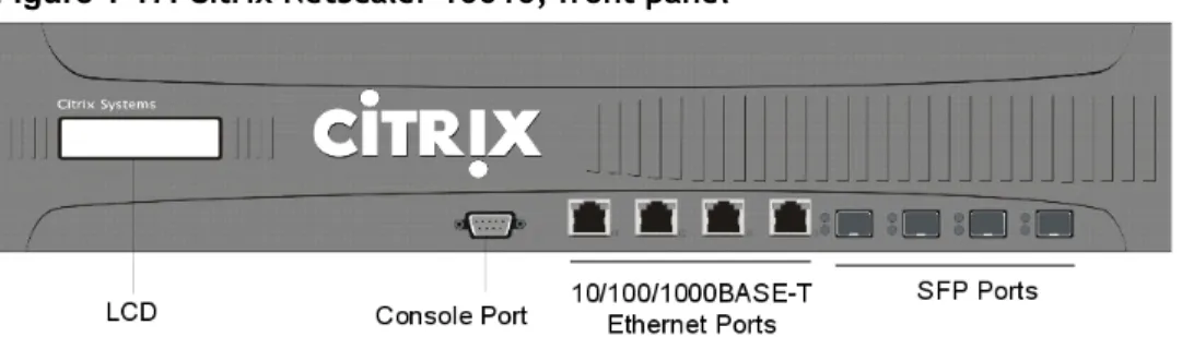
The following figure shows the front panel of the 10010.
Figure 1-17: Citrix NetScaler 10010, front panel
Depending on the model, the following components are visible on the front panel of the 10010:
w Four copper Ethernet 10/100/1000BASE-T ports, numbered 1/5, 1/6, 1/7, and 1/8 from left to right.
w Four Small Form Factor Pluggable (SFP) ports, numbered 1/1, 1/2, 1/3, and 1/4 from left to right. When facing the bezel, the upper LEDs to the left of each optical SFP port inset represent connectivity. They are lit and amber in color when active. The lower LEDs represent throughput. They are lit and green when active.
Note: The network port numbers on all appliances consist of two numbers separated by a forward slash. The first number is the port adapter slot number. The second number is the interface port number. Ports on appliances are numbered sequentially starting with 1.
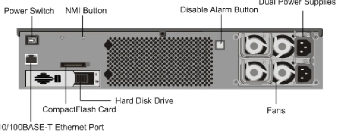
The following figure shows the back panel of the 10010.
Figure 1-18: Citrix NetScaler 10010, back panel
The following components are visible on the back panel of the 10010:
w Power Switch, which turns off power to the 10010, just as if you were to unplug both power supplies.
w Non-maskable interrupt (NMI) button, which signals the 10010 to perform an orderly shutdown after saving all files. You must use a pen, pencil, or other pointed object to press this button, which is located inside a small hole to prevent it being pressed accidentally.
w Disable Alarm Button, which silences the alarm that the 10010 sounds when it is receiving power from only one of its power supplies. Press this button to prevent the power alarm from sounding when you have plugged the 10010 into only one power outlet or when one power supply is malfunctioning and you wish to continue operating the 10010 until it is repaired.
w Dual Power Supplies, each rated at 500 watts, 110-220 volts. You plug separate power cords into the power supplies and connect them to separate wall sockets. The 10010 functions properly with a single power supply; the extra power supply serves as a backup.
w 10/100BASE-T copper Ethernet port, numbered 0/1.
w Removable Hard Disk Drive that is used to store user data.
Citrix NetScaler 12000
The Citrix NetScaler 12000 appliance is a 2U appliance, with 2 single-core processors, and 4 GB of memory. The 12000 is a high-capacity, fault-tolerant hardware platform intended for heavy use in data center environments.
Note: NetScaler 9.1 nCore release is not supported on this hardware platform.
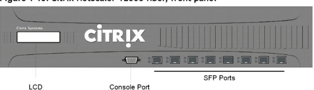
The 12000 comes in four models: the fiber model, the copper model, the mixed model, and the 10G model. The following figure shows the front panel of the 12000 fiber model.
Figure 1-19: Citrix NetScaler 12000 fiber, front panel
The fiber model has eight fiber Small Form Factor Pluggable (SPF) ports. The copper model has eight copper SFP ports instead of eight fiber SFP ports, located in the same places. The mixed model has four copper SFP ports located in the left four positions and four fiber SFP ports located in the right four positions.
The following figure shows the front panel of the 12000-10G model.
Figure 1-20: Citrix 12000-10G, front panel
Depending on the model, the following components are visible on the front panel of the 12000:
w RS232 serial Console Port.
• 12000 Fiber. Eight fiber SFP ports, numbered 1/1, 1/2, 1/3, 1/4, 1/5, 1/6, 1/7, and 1/8 from left to right.
• 12000 Copper. Eight copper SFP ports, numbered 1/1, 1/2, 1/3, 1/4, 1/5, 1/6, 1/7, and 1/8 from left to right.
• 12000 Mixed. Four copper SFP ports, numbered 1/1, 1/2, 1/3, and 1/4, and four fiber SFP ports, numbered 1/5, 1/6, 1/7, and 1/8 from left to right.
• 12000-10G. Eight SFP ports, numbered 1/1, 1/2, 1/3, 1/4, 1/5, 1/6, 1/7, and 1/8 from left to right, and two XFP (10-Gigabit Small Form Factor Pluggable) ports, numbered 1/9 and 1/10. When facing the bezel, the upper LEDs to the left of each optical SFP port represent connectivity. They are lit and amber in color when active. The lower LEDs represent throughput. They are lit and green when active.
Note: The network port numbers on all appliances consist of two numbers
separated by a forward slash. The first number is the port adapter slot number. The second number is the interface port number. Ports on appliances are numbered sequentially starting with 1.
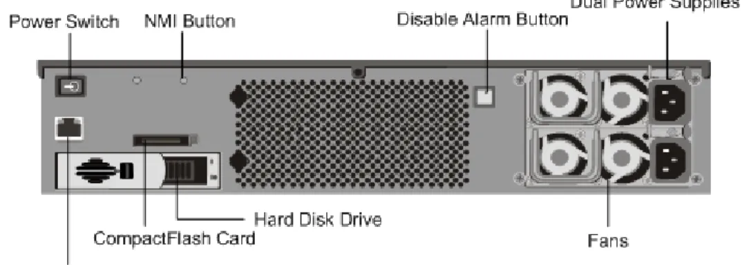
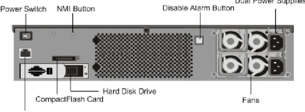
The following figure shows the back panel of all 12000 models.
Figure 1-21: Citrix NetScaler 12000, back panel
The following components are visible on the back panel of the 12000:
w Power switch, which turns off power to the 12000, just as if you were to unplug both power supplies.
w Non-maskable interrupt (NMI) button, which signals the 12000 to perform an orderly shutdown after saving all files. You must use a pen, pencil, or other pointed object to press this button, which is located inside a small hole to prevent it being pressed accidentally.
w Disable Alarm Button, which silences the alarm that the 12000 sounds when it is receiving power from only one of its power supplies. Press this button to prevent the power alarm from sounding when you have plugged the 12000 into only one power outlet or when one power supply is malfunctioning and you wish to continue operating the 12000 until it is repaired.
w Dual Power Supplies, each rated at 500 watts, 110-220 volts. You plug separate power cords into the power supplies and connect them to separate wall sockets. The 12000 functions properly with a single power supply; the extra power supply serves as a backup.
w 10/100BASE-T copper Ethernet port, numbered 0/1.
w Removable CompactFlash Card that is used to store the operating system.
w Removable Hard Disk Drive that is used to store user data.
Citrix NetScaler MPX 5500
The Citrix NetScaler MPX 5500 is a 1U appliance, with 1 dual-core processor, and 4 gigabytes (GB) of memory.
The following figure shows the front panel of the MPX 5500.
Figure 1-22: Citrix NetScaler MPX 5500, front panel
Note: The LCD keypad is not functional in this release.
The MPX 5500 has the following ports:
w RS232 serial Console Port.
w Two 10/100/1000Base-T copper Ethernet Management Ports, numbered 0/1 and 0/2 from left to right. You can use these ports to connect directly to the appliance for system administration functions.
w Four 10/100/1000Base-T copper Ethernet ports numbered 1/1, 1/2, 1/3, and 1/4 from left to right.
Note: The network port numbers on all appliances consist of two numbers separated by a forward slash. The first number is the port adapter slot number. The second number is the interface port number. Ports on appliances are numbered sequentially starting with 1.
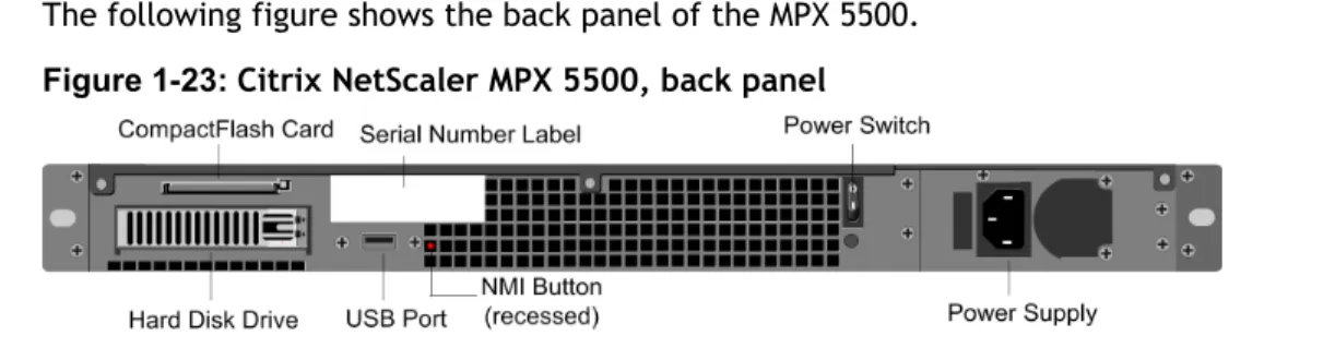
The following figure shows the back panel of the MPX 5500.
The following components are visible on the back panel of the MPX 5500:
w Four GB removable CompactFlash Card that is used to store the operating system.
w Power Switch, which turns off power to the MPX 5500, just as if you were to unplug the power supply. Press the switch for five seconds to turn off the power.
w Removable Hard Disk Drive that is used to store user data.
w USB port (reserved for a future release).
w Non-maskable interrupt (NMI) button, which signals the MPX 5500 to perform an orderly shutdown after saving all files. You must use a pen, pencil, or other pointed object to press this red button, which is located inside a small hole to prevent it being pressed accidentally.
w Power supply rated at 300 watts, 110-220 volts. The power-supply fan is designed to turn on only when the internal temperature of the power supply reaches a certain value. You cannot see the fan turning on the back panel. What you can see is the fixed part of the fan that holds the spinning motor.
Citrix NetScaler MPX 7500 and MPX 9500
The Citrix NetScaler MPX 7500/9500 are 1U appliances, each with 1 quad-core processor, and 8 gigabytes (GB) of memory. The MPX 7500/9500 appliances are available in two port configurations: 8xCopper Ethernet (Cu) and 4xSFP+4xCu. The following figure shows the front panel of the MPX 7500/9500 (8xCu) appliances.
Figure 1-24: Citrix NetScaler MPX 7500/9500 (8xCu), front panel
The following figure shows the front panel of the MPX 7500/9500 (4xSFP+4xCu) appliances.
Figure 1-25: Citrix NetScaler MPX 7500/9500 (4xSFP+4xCu), front panel
Note: The LCD keypad is not functional in this release.
w RS232 serial Console Port.
w Two 10/100/1000Base-T copper Ethernet management ports, numbered 0/1 and 0/2 from left to right. These ports are used to connect directly to the appliance for system administration functions.
w Network Ports
• MPX 7500/9500 (8xCu). Eight 10/100/1000Base-T copper Ethernet ports
numbered 1/1, 1/2, 1/3, and 1/4 on the top row from left to right, and 1/5, 1/6, 1/7, and 1/8 on the bottom row from left to right.
• MPX 7500/9500 (4xSFP+4xCu). Four 1-gigabit copper or fiber SFP ports numbered 1/1, 1/2, 1/3, and 1/4 on the top row from left to right, and four 10/100/1000BASE-T copper Ethernet Ports (RJ45) numbered 1/5, 1/6, 1/7, and 1/8 on the bottom row from left to right.
The following figure shows the back panel of the MPX 7500/9500.
Figure 1-26: Citrix NetScaler MPX 7500/9500, back panel
The following components are visible on the back panel of the MPX 7500/9500:
w Four GB removable compact flash that is used to store the operating system.
w Power Switch, which turns off power to the MPX 7500/9500, just as if you were to unplug the power supply. Press the switch for five seconds to turn off the power.
w Removable Hard Disk Drive that is used to store user data.
w USB port (reserved for a future release).
w Non-maskable interrupt (NMI) Button that is used at the request of Technical Support and produces a core dump on the NetScaler. You must use a pen, pencil, or other pointed object to press this red button, which is recessed to prevent
unintentional activation.
w Disable Alarm Button. This button is functional only when the appliance has two power supplies.
Press this button to stop the power alarm from sounding when you have plugged the MPX 7500/9500 into only one power outlet or when one power supply is
malfunctioning and you want to continue operating the MPX 7500/9500 until it is repaired.
w Power Supplies, each rated at 450 watts, 110-220 volts. The second power supply is optional.
Note: You can order the second power supply through a Citrix sales representative.
Citrix NetScaler MPX 9700, MPX 10500, MPX 12500,
and MPX 15500
The Citrix NetScaler MPX 9700/10500/12500/15500 are 2U appliances, each with 2 quad-core processors, and 16 gigabytes (GB) of memory. All these appliances are also
available in a 10G model.
The following figure shows the front panel of the MPX 9700/10500/12500/15500.
Figure 1-27: Citrix NetScaler MPX 9700/10500/12500/15500, front panel
The following figure shows the front panel of the MPX 9700/10500/12500/15500 10G.
Figure 1-28: Citrix NetScaler MPX 9700/10500/12500/15500 10G, front panel
Note: The LCD keypad is not available in this release.
Depending on the model, the appliance has the following ports:
w RS232 serial Console Port.
w Two 10/100/1000Base-T copper Ethernet Management Ports (RJ45), numbered 0/1 and 0/2 from left to right. These ports are used to connect directly to the appliance for system administration functions.
w Network Ports
• MPX 9700/10500/12500/15500. Eight 1-gigabit copper or fiber SFP ports numbered 1/1, 1/2, 1/3, and 1/4 on the first row from left to right, and 1/5, 1/6, 1/7, and 1/8 on the second row from left to right. Eight 10/100/1000BASE-T copper Ethernet Ports (RJ45) numbered 1/9, 1/10, 1/11, and 1/12 on the third row from left to right, and 1/13, 1/14, 1/15, and 1/16 on the fourth row from left to right.
• MPX 9700/10500/12500/15500 10G. Two 10-gigabit SFP+ Ports numbered 10/1 and 10/2 on the top row, eight 1-gigabit copper or fiber SFP Ports numbered 1/1, 1/2, 1/3, and 1/4 on the middle row from left to right, and 1/5, 1/6, 1/7, and 1/8 on the bottom row from left to right.
Important: The 10-gigabit ports on this appliance are labeled 10/1 and 10/2.
The following figure shows the back panel of the MPX 9700/10500/12500/15500 appliances, including the 10G model.
Figure 1-29: Citrix NetScaler MPX 9700/10500/12500/15500 and MPX 9700/10500/12500/15500 10G, back panel
The following components are visible on the back panel of the MPX 9700/10500/12500/15500, including the 10G model:
w Four GB removable CompactFlash Card that is used to store the operating system.
w Power Switch, which turns off power to the appliance, just as if you were to unplug the power supply. Press the switch for five seconds to turn off the power.
w Removable Hard Disk Drive that is used to store user data.
w USB port (reserved for a future release).
w Non-maskable interrupt (NMI) Button that is used at the request of Technical Support and produces a core dump on the NetScaler. You must use a pen, pencil, or other pointed object to press this red button, which is recessed to prevent
unintentional activation.
w Disable Alarm Button. This button is functional only when the appliance has two power supplies.
Press this button to stop the power alarm from sounding when you have plugged the appliance into only one power outlet or when one power supply is malfunctioning and you want to continue operating the appliance until it is repaired.
w Dual Power Supplies, each rated at 450 watts, 110-220 volts.
Citrix NetScaler MPX 17500, MPX 19500, and MPX
21500
The Citrix NetScaler MPX 17500/19500/21500 are 2U appliances, each with 2 six-core processors, and 48 gigabytes (GB) of memory.
The following figure shows the front panel of the MPX 17500/19500/21500.
Figure 1-30: Citrix NetScaler MPX 17500/19500/21500, front panel
Note: The LCD keypad is not available in this release.
The MPX 17500/19500/21500 appliances have the following ports:
w RS232 serial Console Port.
w Two 10/100/1000Base-T copper Ethernet Management Ports (RJ45), numbered 0/1 and 0/2 from left to right. These ports are used to connect directly to the appliance for system administration functions.
w Eight 10-gigabit SFP+ Ports numbered 10/1, 10/2, 10/3, and 10/4 on the top row from left to right , and 10/5, 10/6, 10/7, and 10/8 on the bottom row from left to right.
The following figure shows the back panel of the MPX 17500/19500/21500.
The following components are visible on the back panel of the MPX 17500/19500/21500:
w 160 GB removable Solid-State Drive that is used to store the operating system.
w USB port (reserved for a future release).
w Power Switch, which turns off power to the appliance, just as if you were to unplug the power supply. Press the switch for five seconds to turn off the power.
w Non-maskable interrupt (NMI) Button that is used at the request of Technical Support and produces a core dump on the NetScaler. You must use a pen, pencil, or other pointed object to press this red button, which is recessed to prevent
unintentional activation.
w Removable Hard Disk Drive that is used to store user data.
w Disable Alarm Button. This button is functional only when the appliance has two power supplies.
Press this button to stop the power alarm from sounding when you have plugged the appliance into only one power outlet or when one power supply is malfunctioning and you want to continue operating the appliance until it is repaired.
w Dual Power Supplies, each rated at 650 watts, 110-220 volts.
Citrix NetScaler MPX 15000
The Citrix NetScaler MPX 15000 appliance is a 2U appliance, with 2 dual-core processors, and 16 GB of memory. The MPX 15000 is a high-capacity, fault-tolerant hardware platform intended for heavy use in enterprise and service provider environments. The following figure shows the front panel of the MPX 15000.
Figure 1-32: Citrix NetScaler MPX 15000, front panel
The appliance has the following ports:
w RS232 serial Console Port.
w 10/100/1000BASE-T copper Ethernet Management Port, numbered 0/1.
w Two XFP (10-Gigabit Small Form Factor Pluggable) fiberoptic ports, numbered from left to right 1/1 and 1/2.
w Eight 10/100/1000BASE-T copper Ethernet ports, numbered from upper left to bottom right 1/3, 1/4, 1/5, 1/6, 1/7, 1/8, 1/9, and 1/10.
When facing the bezel, the upper LEDs to the left of each port represent connectivity. They are lit and amber in color when active. The lower LEDs represent throughput. They are lit and green when active.
Note: The network port numbers on all appliances consist of two numbers separated by a forward slash. The first number is the port adapter slot number and will always be either 0 or 1. The second number is the interface port number. Ports on appliances are numbered sequentially starting with 1.
The following figure shows the back panel of the MPX 15000.
Figure 1-33: Citrix NetScaler MPX 15000, back panel
The following components are visible on the back panel of the MPX 15000:
w Removable Hard Disk Drive that is used to store user data.
w Dual Power supplies, each rated at 500 watts, 110-220 volts.
You plug separate power cords into the power supplies and connect them to
separate wall sockets. The MPX 15000 functions properly with a single power supply; the extra power supply serves as a backup.
w Non-maskable interrupt (NMI) button, which signals the MPX 15000 to perform an orderly shutdown after saving all files. You must use a pen, pencil, or other pointed object to press this button, which is located inside a small hole to prevent it being pressed accidentally.
w Removable CompactFlash Card that is used to store the operating system.
Citrix NetScaler MPX 17000
The Citrix NetScaler MPX 17000 appliance is a 2U appliance, with 2 quad-core processors, and 32 GB of memory. The MPX 17000 is a high-capacity, fault-tolerant hardware platform intended for any high traffic, intensive processing data center environment. There are two MPX 17000 models: the four network-port model and the ten network-port model. The following figure shows the front panel of the MPX 17000, four network-port model.
Figure 1-34: Citrix NetScaler MPX 17000 four network-port model, front panel
Depending on the model, the appliance has the following ports:
w RS232 serial Console Port.
w 10/100/1000BASE-T copper Ethernet Management Port, numbered 0/1.
w Network Ports
• MPX 17000 four network-port model. Four XFP (10-Gigabit Small Form Factor Pluggable) ports, numbered from upper left to bottom right 1/1, 1/2, 1/3, and 1/4.
• MPX 17000 ten network-port model. Two XFP ports, numbered from left to right 1/1 and 1/2 and eight 10/100/1000BASE-T Ethernet ports, numbered from upper left to bottom right 1/3, 1/4, 1/5, 1/6, 1/7, 1/8, 1/9 and 1/10.
Note: The network port numbers on all appliances consist of two numbers
separated by a forward slash. The first number is the port adapter slot number and will always be either 0 or 1. The second number is the interface port number. Ports on appliances are numbered sequentially starting with 1.
When facing the bezel, the upper LEDs to the left of each port represent connectivity. They are lit and amber in color when active. The lower LEDs represent throughput. They are lit and green when active.
The following figure shows the back panel of the MPX 17000.
Figure 1-35: Citrix NetScaler MPX 17000, back panel
w Removable Hard Disk Drive that is used to store user data.
w Dual Power supplies, each rated at 500 watts, 110-220 volts.
You plug separate power cords into the power supplies and connect them to
separate wall sockets. The MPX 17000 functions properly with a single power supply; the extra power supply serves as a backup.
w Non-maskable interrupt (NMI) button, which signals the MPX 17000 to perform an orderly shutdown after saving all files. You must use a pen, pencil, or other pointed object to press this button, which is located inside a small hole to prevent it being pressed accidentally.
w Removable CompactFlash Card that is used to store the operating system.
Summary of Hardware Specifications
The following tables summarize the specifications of the hardware platforms.
Table 1-5: Standard Platform Summary
7000 9010 10010 12000
Processor 1 single-core 1 single-core 1 single-core 2 single-cores
Memory 1 GB 2 GB 4 GB 4 GB
Number of Power Supplies
1 2 2 2
Power Supply input voltage & frequency 100-240/ 47-63Hz 100-240/ 47-63Hz 100-240/ 47-63Hz 100-240/ 47-63Hz Maximum Power Consumption 250 W 500 W 500 W 500W Weight (lbs.) 28 52 52 52 Height 1U 2U 2U 2U
Width EIA 310-D EIA EIA 310-D EIA 310-D EIA 310-D Depth 24 in/ 61 cm 24 in/ 61 cm 24 in/ 61 cm 24 in/ 61 cm
7000 9010 10010 12000 Operating Temperature (degree celsius) 0-40 0-40 0-40 0-40 Humidity range (non-condensing) 5%-95% 5%-95% 5%-95% 5%-95% Safety Certifi-cations
TUV TUV TUV TUV
EMC & Susceptibility FCC Class A, CB, FCC, CE, VCCI, C-Tick, NOM, SASO/ CITC FCC Class A, CB, FCC, CE, VCCI, C-Tick, NOM FCC Class A, CB, FCC, CE, VCCI, C-Tick, NOM, SASO/ CITC FCC Class A, CB, FCC, CE, VCCI, C-Tick, NOM, SASO/ CITC
Compliance RoHS, WEEE RoHS, WEEE RoHS, WEEE RoHS, WEEE
Table 1-6: MPX Platform Summary MPX 5500 MPX 7500/ MPX 9500 MPX 9700/ MPX 10500/ MPX 12500/ MPX 15500 MPX 17500/MPX 19500/MPX 21500 MPX 15000 MPX 17000 Processo rs 1 dual-core 1 dual-core 2 quad-core 2 six-core 2 quad-core 2 quad-core Memory 4 GB 8 GB 16 GB 48 GB 16 GB 32 GB Number of Power Supplies 1 1 with second optional 2 2 2 2 Power Supply input voltage & 90-264VA C 47-63 Hz 90-264VA C 47-63 Hz 90-264VAC 47-63 Hz 100-240VAC 50-60 Hz 100-240V AC 47-63Hz 100-240V AC 47-63Hz
MPX 5500 MPX 7500/ MPX 9500 MPX 9700/ MPX 10500/ MPX 12500/ MPX 15500 MPX 17500/MPX 19500/MPX 21500 MPX 15000 MPX 17000 frequenc y Maximu m Power Consump tion 300 W 450 W 450 W 650W 700W 700W Weight (lbs.) 22 23 with one power supply 31 40 52 52 Height 1U 1U 2U 2U 2U 2U Width 310-D EIA
310-D EIA 310-D EIA EIA 310-D 310-D EIA 310-D
Depth 21.75 in/ 55 cm 21.75 in/ 55 cm 24.5 in/ 62 cm 24.75 in/ 62.865 cm 18.5 in/ 47 cm 18.5 in/ 47 cm Operatin g Tempera ture (degree celsius) 0-40 0-40 0-40 0-40 0-35 0-35 Humidity range (non-condensi ng) 5%-95% 5%-95% 5%-95% 5%-95% 5%-95% 5%-95% Safety Certifi-cations
CSA CSA CSA CSA UL & TUV-C
UL & TUV-C
MPX 5500 MPX 7500/ MPX 9500 MPX 9700/ MPX 10500/ MPX 12500/ MPX 15500 MPX 17500/MPX 19500/MPX 21500 MPX 15000 MPX 17000 EMC & Suscepti bility FCC (Part 15 Class A), CE, C-Tick, CCC, KCC, NOM, PCT, VCCI, SASO, SABS FCC (Part 15 Class A), CE, C-Tick, CCC, KCC, NOM, PCT, VCCI, SASO, SABS FCC (Part 15 Class A), CE, C-Tick, CCC, KCC, NOM, PCT, VCCI, SASO, SABS FCC (Part 15 Class A), CE, C-Tick, VCCI FCC (Part 15 Class A), DoC, CE, VCCI, CNS, AN/ NES FCC (Part 15 Class A), DoC, CE, VCCI, CNS, AN/ NES Complia nce RoHS, WEEE RoHS, WEEE RoHS, WEEE
RoHS, WEEE RoHS, WEEE
RoHS, WEEE
Preparing for Installation
Topics:
• Unpacking the NetScaler Appliance
• Preparing the Site and Rack
• Cautions and Warnings
Before you install your new NetScaler appliance, carefully unpack your NetScaler and make sure that all parts were delivered. Once you are satisfied that your NetScaler has been delivered to your expectations, verify that the location where the NetScaler will be installed meets temperature and power requirements and that the server cabinet or floor-to-ceiling cabinet is securely bolted to the floor and has sufficient airflow. Only trained and qualified personnel should install, maintain, or replace the appliance and efforts should be taken to ensure that all cautions and warnings are followed.
Unpacking the NetScaler Appliance
The hardware accessories for your particular appliance, such as cables, adapters, and rail kit, will vary depending on the hardware platform you ordered. Unpack the box that contains your new appliance on a sturdy table with plenty of space and inspect the contents.
Use the following list to verify that you received everything that should have been included in the box.
w The appliance you ordered. For a description and illustration of your particular model, see Hardware Platforms on page 23.
w One RJ-45 to DB-9 adapter
w One 6 ft RJ-45/DB-9 cable
w The following list specifies the number of power cables included for each appliance model:
• One power cable for the 7000, MPX 5500, and MPX 7500/9500 appliances • Two power cables for the 9010, 10010, 12000, MPX 15000, MPX 17000, MPX
9700/10500/12500/15500, and MPX 17500/19500/21500 appliances
Note: Ensure that a power outlet is available for each cable. w One mounting rail kit with all the models
In addition to the items included in the box with your new appliance, you will need the following items to complete the installation and initial configuration process.
w Ethernet cables for each additional Ethernet port that you will connect to your network
w One available Ethernet port on your network switch or hub for each NetScaler Ethernet port you want to connect to your network
Note: Transceiver modules are sold separately. Please contact your Citrix sales representative to order transceiver modules for your appliance. Only transceivers supplied by Citrix are supported on the appliance.
w A computer to serve as a management workstation
Preparing the Site and Rack
There are specific site and rack requirements for the NetScaler appliance. You must make sure that adequate environmental control and power density are available. Racks must be bolted to the ground, have sufficient airflow, and have adequate power and network connections. Preparing the site and rack are important steps in the installation process and will help ensure a smooth installation.
Site Requirements
The appliance should be installed in a server room or server cabinet with the following features:
Environment control.
An air conditioner, preferably a dedicated computer room air conditioner (CRAC), capable of maintaining the cabinet or server room at a temperature of no more than 21 degrees C/70 degrees F at altitudes up to 2100 m/7000 ft, or 15 degrees C/60 degrees F at higher altitudes, a humidity level no greater than 45 percent, and a dust-free environment.
Power density.
Wiring capable of handling at least 4,000 watts per rack unit in addition to power needs for the CRAC.
Rack Requirements
The rack on which you install your appliance should meet the following criteria:
Rack characteristics.
Racks should be either integrated into a purpose-designed server cabinet or be the floor-to-ceiling type, bolted down at both top and bottom to ensure stability. If you have a cabinet, it should be installed perpendicular to a load-bearing wall for stability and sufficient airflow. If you have a server room, your racks should be installed in rows spaced at least 1 meter/3 feet apart for sufficient airflow. Your rack must allow your IT personnel unfettered access to the front and back of each server and to all power and network connections.
Power connections.
At minimum, two standard power outlets per unit.
Network connections.
At minimum, four Ethernet connections per rack unit.
Space requirements.
One empty rack unit for the Citrix NetScaler 7000, MPX 5500, and MPX 7500/MPX 9500, and two consecutive empty rack units for all other appliance models.
Cautions and Warnings
The NetScaler installation instructions provide instructions for carefully connecting the appliance to a power source. Heed all cautions and warnings regarding safety practices when working with power sources. To help ensure secure rack installation, sufficient airflow, and appliance stability, follow all prescribed precautions.
Caution: Only trained and qualified personnel should install, maintain, or replace the appliance.
Electrical Safety Precautions
Basic electrical safety precautions should be followed to protect yourself from harm and the appliance from damage.
w Be aware of the location of the emergency power off (EPO) switch. If an electrical accident occurs, you can quickly remove power from the appliance.
w Remove all jewelry and other metal objects that might come into contact with power sources or wires before installing or repairing the appliance. When you touch both a live power source or wire and ground, any metal objects can heat up rapidly, and may cause burns, set clothing on fire, or fuse the metal object to an exposed terminal.
w Use of a regulating uninterruptible power supply (UPS) protects the appliance from power surges and voltage spikes and keeps the appliance operating in case of power failure.
w Never stack the appliance on top of any other server or electronic equipment.
w All appliances are designed to be installed on power systems that use TN earthing. Do not install your device on a power system that uses either TT or IT earthing.
w Ensure that the appliance has a direct physical connection to the earth during normal use. When installing or repairing an appliance, always make sure that the ground circuit is connected first and disconnected last.
w Ensure that a fuse or circuit breaker no larger than 120 VAC, 15 A U.S. (240 VAC, 16 A international) is used on all current-carrying conductors on the power system to which your appliances are connected.
w Do not work alone when working with high voltage components.
w Always disconnect power from the appliance when removing or installing any component. When disconnecting power, you should first shut down the appliance and then unplug the power cords of all the power supply units connected to the appliance. As long as the power cord is plugged in, line voltages are present in the power supply even when the power switch is off.
w Do not use mats designed to decrease static electrical discharge as protection from electrical shock. Instead, use rubber mats that have been specifically designed as electrical insulators.
w Make sure that the power source can handle the appliance's maximum power consumption rating with no danger of an overload.Always unplug any appliance before performing repairs or upgrades.
w Do not overload the wiring in your server cabinet or on your server room rack.
w During thunderstorms, or anticipated thunderstorms, avoid performing any hardware repairs or upgrades until the danger of lightning has passed.
w When you dispose of an old appliance or any components, follow any local and national laws on disposal of electronic waste.
w To prevent possible explosions, replace expired batteries with the same model or a manufacturer-recommended substitute and follow the manufacturer’s instructions on battery replacement.
w Never remove a power supply cover or any sealed part that has the following label:
Appliance Precautions
w Determine the placement of each component in the rack before you install the rail.
w Install the heaviest appliance at the bottom of the rack first, and then work up. Distribute the load on the rack evenly. An unbalanced rack is hazardous.
w Allow the power supply units and hard drives to cool before touching them.
w Install the equipment near a socket outlet for easy access.
w Mount equipment into a rack with sufficient airflow for safe operation.
w For a closed or multi-unit rack assembly, the ambient operating temperature of the rack environment may be greater than the ambient temperature of the room. Therefore, consider the lowest and highest operating temperatures of the
equipment when making a decision about where to install the appliance in the rack.
Rack Precautions
w Make sure that the leveling jacks on the bottom of the rack are fully extended to the floor, with the full weight of the rack resting on them.
w For a single-rack installation, attach a stabilizer to the rack.
w Always make sure the rack is stable before extending a component from the rack.
w Extend only one component at a time, extending two or more simultaneously may cause the rack to become unstable.
w The handles on the left and right of the front panel of the appliance should only be used for extending the appliance out of the rack. These handles should not be used for mounting the appliance on the rack. Rack-rail hardware described earlier should be used instead.
Installing the Hardware
Topics:
• Rack Mounting the Appliance
• Installing and Removing SFP Transceivers
• Installing and Removing XFP and SFP+ Transceivers
• Connecting the Cables
• Turning on the Appliance
After you have determined that the location where you will install your appliance meets the environmental standards and the server rack is in place according to the instructions, you are ready to install the hardware. After you mount the appliance, you are ready to connect it to the network, to a power source, and to the console terminal that you will use for initial configuration. To complete the installation, you turn on the appliance. Be sure to observe the cautions and
Rack Mounting the Appliance
Most appliances can be installed in standard server racks. The appliances ship with a set of rails, which you must install before you mount the appliance. The only tool you will need to install an appliance is a Phillips screwdriver.
Caution: If you are installing the appliance as the only unit in the rack, mount it at the bottom. If the rack contains other units, make sure that the heaviest unit is at the bottom. If the rack has stabilizing devices available, install them before mounting the appliance.
The 7000, MPX 5500, MPX 7500/9500 appliances each require one rack unit. The 9010, 10010, 12000, MPX 9700/10500/12500/15500, MPX 15000, MPX 17000, and MPX 17500/19500/21500 appliances each require two rack units. Each of these units ships with a mounting rail kit that contains two rail assemblies, one for the left side and the other for the right side of the appliance, and screws to attach the rails. An assembly consists of an inner rail and a rack rail.
To mount the appliance, you must first install the rails and then install the appliance in the rack.
Perform the following tasks to mount the appliance:
w Remove the inner rails from the rail assembly.
w Attach the inner rails to the appliance.
w Install the rack rails on the rack.
w Install the appliance in the rack.
To remove the inner rails from the rail assembly
1. Place the rail assembly on a flat surface.
2. Slide out the inner rail toward the front of the assembly.
3. Depress the locking tabs until the inner rail comes all the way out of the rail assembly, as shown in the following figure.
Figure 3-1: Removing inner rails
4. Repeat steps 1 through 3 to remove the second inner rail.
To attach the inner rails to the appliance
1. Position the right inner rail behind the ear bracket on the right side of the appliance.
2. Align the holes on the rail with the corresponding holes on the side of the appliance. 3. Attach the rail to the appliance with screws, as shown in the following figure.
Figure 3-2: Attaching inner rails
4. Repeat steps 1 through 3 to install the left inner rail on the left side of the appliance.
To install the rack rails
1. Position the rack rails at the desired location in the rack, keeping the sliding rail guide facing inward.
2. Snap the tool-less rails to the rack.
Note: Make sure that both rack rails are at same height and that the rail guides are facing inward.
To install the appliance in the rack
1. Align the inner rails, attached to the appliance, with the rack rails.
2. Slide the appliance into the rack rails, keeping the pressure even on both sides. 3. Verify that the appliance is locked in place by pulling it all the way out from the
rack.
Figure 3-3: Rack mounting the appliance
Installing and Removing SFP Transceivers
Note: This section applies to the 9010, 10010, 12000, and MPX9700/10500/12500/15500 appliances.
A Small Form Factor Pluggable (SFP) is a compact transceiver that can operate at speeds of up to 1 gigabit per second and is available in both copper and fiber types. Inserting an SFP copper transceiver converts the SFP port to a 1000BASE-T port. Inserting an SFP fiber transceiver converts the SFP port to a 1000BASE-X port. Auto-negotiation is enabled by default on the SFP port into which you insert your SFP transceiver. As soon as a link between the port and the network is established, the speed and mode are matched on both ends of the cable.
Caution: Only SFP transceivers provided by Citrix Systems are supported on NetScaler appliances. Attempting to install third-party SFP transceivers on your NetScaler appliance voids the warranty.
Insert SFP transceivers into the SFP ports on the front panel of the appliance. Frequent installation and removal of transceivers shortens their life span. Follow the removal procedure carefully to avoid damaging the SFP transceiver or the appliance.