Grand Valley State University
ScholarWorks@GVSU
Masters Theses Graduate Research and Creative Practice
2-2019
A Comparative study of Wireless Star Networks
Implemented with Current Wireless Protocols
Sizen Neupane
Grand Valley State University
Follow this and additional works at:https://scholarworks.gvsu.edu/theses
Part of theHardware Systems Commons
This Thesis is brought to you for free and open access by the Graduate Research and Creative Practice at ScholarWorks@GVSU. It has been accepted for inclusion in Masters Theses by an authorized administrator of ScholarWorks@GVSU. For more information, please contact
Recommended Citation
Neupane, Sizen, "A Comparative study of Wireless Star Networks Implemented with Current Wireless Protocols" (2019).Masters Theses. 920.
A Comparative study of Wireless Star Networks Implemented with Current Wireless Protocols Sizen Neupane
A Thesis Submitted to the Graduate Faculty of GRAND VALLEY STATE UNIVERSITY
In
Partial Fulfillment of the Requirements For the Degree of
Masters of Science in Engineering
Padnos College of Engineering and Computing
3
Acknowledgments
I would like to express the deepest appreciation to my committee chair, Dr. Robert Bossemeyer for constantly guiding and supporting me to complete this thesis. I would like to thank my committee members, Dr. Nabeeh Kandalaft and Dr. Bruce Dunne for providing necessary feedback and guidance to improve my thesis. I am very thankful to Dr. Bossemeyer and Dr. Jiao for the Embedded System Interface class, where I learned about MSP432 and nRF24L01+, including SPI and different design techniques. I would like to thank Mr. Neil Kolban for
providing the library for ESP32 BLE implementation. Lastly, I would like to express my sincere gratitude to my graduate advisor Dr. Shabbir Choudhuri, for guiding me throughout my master’s program.
4
Abstract
Wireless communication is one of the most advanced technological developments of this era. Wireless technology enables both short-range and long-range services. Today, there are several different wireless communication technologies in existence. Each has its characteristics different from another one. This thesis will implement three short-range wireless technologies in star connection and compare the performance in the wireless network.
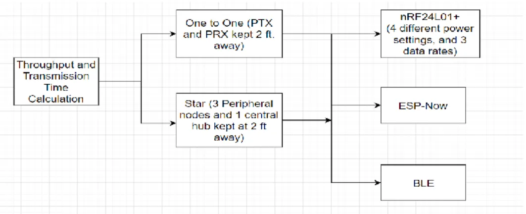
For this thesis, the performance of three different RF protocols - a proprietary packet protocol called Enhanced ShockBurst in nRF24L01+, Bluetooth Low Energy, and a special Wi-Fi protocol ESP-Now was compared. The general concept was to establish a star network for these protocols consisting of each module as a central hub while the others as end nodes, where all modules were configured as transceivers. The wireless star network for the proprietary radio frequency protocol Enhanced ShockBurst Feature was implemented using a transceiver device built by a Norwegian company Nordic Systems called the nRF24L01+. Similar wireless
networks were also implemented for Now and BLE in an ESP32 development board. ESP-Now is a proprietary radio frequency protocol developed by a Chinese company called Espressif that allows multiple devices to connect over 2.4 GHz channels using elements of a Wi-Fi
protocol without requiring a router to form a network, while Bluetooth Low Energy is a wireless personal network designed by the Bluetooth Special Interest Group (Bluetooth SIG).
Different performance metrics such as throughput (kbps), range (ft), current consumption (mA) and network routing recovery time (s) were measured in the network. From the
implementations tested, it was found that the nRF24L01+ has maximum throughput when transmitting large payloads (344% higher than ESP-Now in 32 bytes payload size, BLE
5
throughput was 50.50 bps in 32 bytes payload size), least current consumption (ESP-Now consumes 714% more current and BLE consumes 409.7% more current), and shortest network recovery time (nRF24L01+ took 335us, ESP-Now took 31ms and BLE took 1.3s on average), while the Wi-Fi based ESP-Now has a maximum range (30.53% better than BLE and 120% better than nRF24L01+).
6
Table of Contents
Acknowledgments... 3 Abstract ... 4 Table of Contents ... 6 List of Tables ... 10 List of Figures ... 13 Abbreviations ... 16 1 Introduction ... 18 1.1 Background ... 18 1.2 Terminology ... 19 1.2.1 Network Metrics ... 19 1.2.2 Network Topology ... 22 1.2.3 Wireless Technology ... 23 1.3 Description of Components ... 24 1.3.1 Hardware Description ... 24 1.3.2 Software Description ... 55 1.4 Purpose ... 57 1.5 Thesis Organization... 57 2 Review of Literature ... 593 Design and Implementation of the System ... 63
3.1 Experimental Setup ... 63
7
3.2.1 nRF24L01+ ... 64
3.2.2 ESP32 BLE ... 72
3.2.3 ESP-Now... 82
3.2.4 Measurement of Performance Metrics ... 91
4 Result ... 100
4.1 Throughput ... 100
4.1.1 nRF24L01+ ... 100
4.1.2 BLE and ESP-Now ... 107
4.2 Range ... 112
4.2.1 One to One ... 112
4.2.2 Star Connection ... 114
4.3 Network Recovery Time ... 116
4.3.1 Power Removed ... 116
4.3.2 Out of Range ... 118
4.4 Current Measurement ... 121
4.4.1 nRF24L01+ ... 121
4.4.2 ESP-Now and BLE ... 126
5 Discussion ... 128
5.1 Throughput ... 128
5.1.1 Performance of nRF24L01+ in different configurations ... 128
5.1.2 Comparison of three protocols ... 129
5.2 Range ... 132
8
5.4 Current Measurement ... 134
5.4.1 Performance of nRF24L01+ in different configurations ... 134
5.4.2 Comparison of three protocols ... 137
5.5 Bandwidth, Spectral Efficiency and Noise Reduction ... 138
5.6 Maximum Payload Size ... 139
5.7 Security... 140 5.8 Design cost ... 140 6 Conclusion ... 142 6.1 Summary ... 142 6.2 Future Work ... 143 Appendix A ... 145
A.1 Transmission Times ... 145
A.1.1 nRF24L01+ ... 145
A.1.2 ESP-Now ... 154
A.1.3 BLE ... 158
Appendix B ... 163
B.1 Network Recovery Time ... 163
B.2 Range ... 164
Appendix C ... 165
C.1 Current Measurement ... 165
Appendix D ... 168
D.1 nRF24L01+ Code (Star) ... 168
9
D.3 ESP-Now Code (Star) ... 189 REFERENCES ... 200
10
List of Tables
Table 1: Average transmission time and calculated throughput for 32 bytes ... 102
Table 2: Average transmission time and calculated throughputs for 1 byte ... 103
Table 3: Average transmission time and calculated throughputs for 4 bytes ... 103
Table 4: Average transmission time and calculated throughput for 16 bytes ... 103
Table 5: Throughput and Time Taken for 32 bytes (Star Network) ... 106
Table 6: Throughput and Transmission Time for 1 byte (Star Network) ... 106
Table 7: Transmission Time and Throughput for 4 bytes (Star Network) ... 107
Table 8: Throughput and Transmission Time for 16 bytes (Star Network) ... 107
Table 9: Throughput and Transmission time for ESP-Now in different Payload sizes ... 109
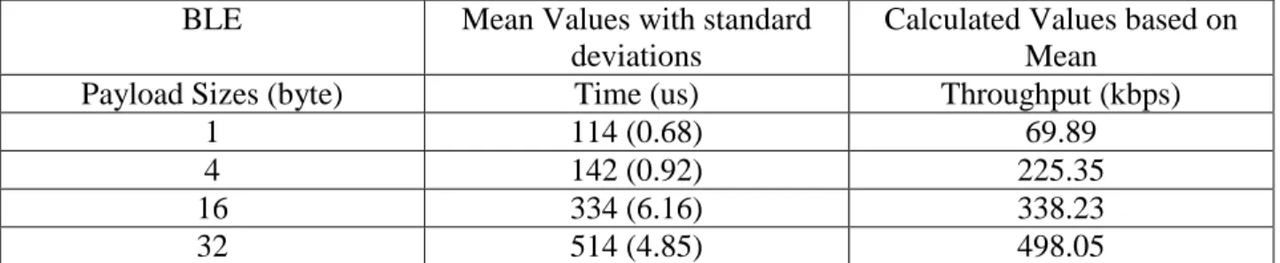
Table 10: Throughput and Transmission time for BLE in different Payload sizes ... 110
Table 11: Throughput and Transmission Time in ESP-Now in Star Connection... 111
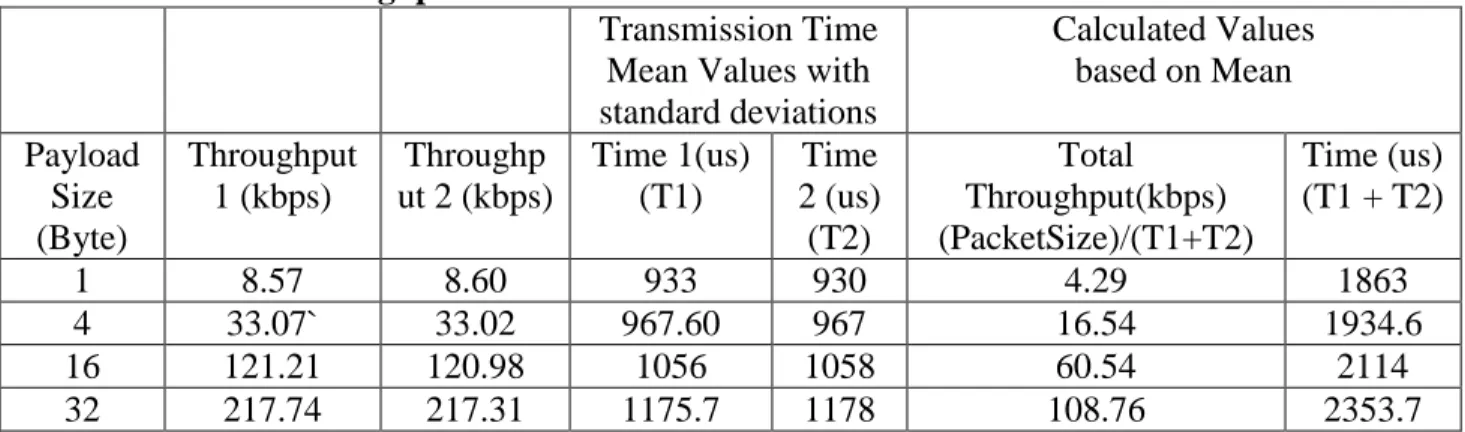
Table 12: Throughput and Transmission Time in BLE in Star Connection ... 111
Table 13: Range of nRF24L01+, ESP-Now and BLE in One to One connection ... 114
Table 14: Range of nRf24L01+, ESP-Now and BLE in a star connection ... 116
Table 15: Current Consumption of nRF24L01+ at 0 dBm in different data rates and delays .... 125
Table 16: Current Consumption of nRF24L01+ in receiver side at 0 dBm in different data rates and delays... 125
Table 17: Measured Current values in 0 dBm power (TX) ... 126
Table 18: Measured Current values in 0 dBm power (RX) ... 126
Table 19: Current Measurement of BLE ... 126
Table 20: Current Measurement of ESP-Now ... 127
11
Table 22: Comparison of Throughput of three protocols in Star connection ... 131
Table 23: Comparison of Network Recovery Time between three protocols ... 134
Table 24: Comparison of Current Values in Transmitter ... 137
Table 25: Comparison of Current Values in Receiver ... 137
Table 26: Maximum Payload Sizes in Three Protocols ... 139
Table 27: Cost of radio modules ... 141
Table 28: Transmission Time values for static payload length (32 bytes) ... 145
Table 29: Transmission Time values for 1 byte ... 146
Table 30: Transmission Time values for 4 bytes ... 147
Table 31: Transmission Time values for 16 bytes ... 148
Table 32: Transmission Time values for 32 bytes in star connection ... 149
Table 33: Transmission Time values for 1 byte in star connection ... 150
Table 34: Transmission Time values for 4 bytes in star connection ... 151
Table 35: Transmission Time values for 16 bytes in star connection ... 152
Table 36: Transmission Time of ESP-Now for 1 byte ... 154
Table 37: Transmission Time of ESP-Now for 4 bytes ... 155
Table 38: Transmission Time of ESP-Now for 16 bytes ... 156
Table 39: Transmission Time of ESP-Now for 32 bytes ... 157
Table 40: Transmission Time of BLE for 1 byte ... 158
Table 41: Transmission Time of BLE for 4 bytes ... 159
Table 42: Transmission Time of BLE for 16 bytes ... 160
Table 43: Transmission Time of BLE for 32 bytes ... 161
12
Table 45: Measured Range values for three protocols in one to one connection ... 164
Table 46: Current Consumption in Min 6 dBm power ... 165
Table 47: Current Consumption in Min 12 dBm power ... 165
Table 48: Current Consumption in Min 18 dBm power ... 165
Table 49: Current Consumption in Min 6 dBm power (PRX)... 166
Table 50: Current Consumption in Min 12 dBm power (PRX)... 166
Table 51: Current Consumption in Min 18 dBm power (PRX)... 166
Table 52: Measured Current values in Min 12 dBm power (TX)... 167
Table 53: Measured Current values in Min 18 dBm power (TX)... 167
Table 54: Measured Current values in Min 12 dBm power (RX) ... 167
13
List of Figures
Figure 1: Star Network... 22
Figure 2: Block Diagram of MSP432 Launchpad [1] ... 25
Figure 3: Functional Block Diagram of MSP432 Launchpad [2]... 26
Figure 4: Functional Block Diagram of nRF24L01+ [3] ... 31
Figure 5: Data Transfer Timing Diagram in ShockBurst [3] ... 34
Figure 6: TX FIFO (PRX) with Pending Payloads [3] ... 35
Figure 7: Data Pipe Addressing in Multiceiver [3] ... 36
Figure 8: Functional Block Diagram of ESP32 [5] ... 38
Figure 9: BLE Frequency Channels [6] ... 39
Figure 10: BLE Broadcast Topology [13] ... 42
Figure 11: BLE Connected Topology [13] ... 43
Figure 12: BLE Architecture [14] ... 46
Figure 13: Status Transitions among GAPs [11] ... 47
Figure 14: Common Operations between a Server and a Client [11] ... 49
Figure 15: The Definition Table of service [11] ... 50
Figure 16: Wi-Fi Channels on the 2.4 GHz Frequency band [15] ... 51
Figure 17: MSP432 Connection with nRF24L01+ ... 63
Figure 18: Transmitter Side in nRF24L01+ ... 66
Figure 19: Receiver Side in nRF24L01+ ... 68
Figure 20: Central Hub in Star Connection ... 70
14
Figure 22: BLE Server ... 74
Figure 23: BLE Client ... 76
Figure 24: Central Hub in BLE in Star Connection ... 79
Figure 25: Peripheral Node in BLE in Star ... 81
Figure 26: ESP-Now Master ... 84
Figure 27: Slave side in ESP-Now... 86
Figure 28: Central Hub in Star Connection of ESP-Now ... 88
Figure 29: Peripheral node (ESP-Now) in Star Connection ... 90
Figure 30: Throughput Calculation Methods ... 91
Figure 31: Current Measurement Circuit ... 94
Figure 32: Experiment Procedure of Range Measurement in Star Network ... 99
Figure 33: Distribution of Transmission Time at 250 Kbps ... 101
Figure 34: Distribution of Transmission Time at 1 Mbps ... 101
Figure 35: Distribution of Transmission Time at 2 Mbps ... 102
Figure 36: Distribution of Transmission time in Star Connection (32 Bytes) ... 104
Figure 37: Distribution of Transmission time in Star Connection (32 Bytes) ... 105
Figure 38: Distribution of Transmission time in Star network (32 Bytes) ... 105
Figure 39: Distribution of Transmission time in ESP-Now... 108
Figure 40: Distribution of Transmission time in BLE ... 109
Figure 41: Distribution of Transmission time in Star Network (ESP-Now) ... 110
Figure 42: Distribution of Range in nRF24L01+ (0dBm) ... 112
Figure 43: Distribution of Range in BLE ... 113
15
Figure 45: Range of nRF24L01+ in a star network ... 114
Figure 46: Range of BLE in a star network ... 115
Figure 47: Range of ESP-Now in a star network ... 115
Figure 48: Distribution of Network Recovery Time in nRF24L01+ (power removed) ... 116
Figure 49: Distribution of Network Recovery Time in ESP-Now (Power Removed) ... 117
Figure 50: Distribution of Network Recovery Time in BLE (Power Removed) ... 118
Figure 51: Distribution of Network Recovery Time in nRF24L01+ (out of range) ... 119
Figure 52: Distribution of Network Recovery Time in ESP-Now (out of range) ... 120
Figure 53: Distribution of Network Recovery Time in BLE (out of range) ... 120
Figure 54: Current Consumption of nRF24L01+ ... 121
Figure 55: EnergyTrace plot when nRF24L01+ starts transmitting ... 122
Figure 56: EnergyTrace Measurement at 2.5 us delay at MAX Power and 1Mbps ... 123
Figure 57: EnergyTrace Measurement at 2.5 us delay at MAX Power and 2Mbps ... 124
Figure 58: Throughput of nRF24L01+ in different Data rates ... 128
Figure 59: Comparison of Throughput in Star, One to One and ACK_Payload (Star) ... 129
Figure 60: Comparison of Throughput in One to One connection ... 130
Figure 61: Comparison of Throughput in Star Connection ... 132
Figure 62: Comparison of range between nRF24L01+, BLE and ESP-Now in Star Connection. ... 133
Figure 63: Current Consumption of PTX at Different Data Rate at MAX Power using EnergyTrace ... 135
Figure 64: Current Consumption in Transmit Condition at Different Power Ratings ... 135
Figure 65: Current Consumption at Different Delays at MAX Power (0 dBm) and MAX Data Rate (2Mbps) ... 136
16
Abbreviations
ACK : Acknowledgment
ADC : Analog to Digital Converter AES : Advanced Encryption Standard AP : Access Point
ATT : Attribute Protocol BLE : Bluetooth Low Energy CE : Chip Enable
CRC : Cyclic Redundancy Check CS : Chip Select
DAC : Digital to Analog Converter dBm : decibels relative to one milliwatt FIFO : First-in, First-out
GAP : Generic Access Profile GATT : Generic Attribute
GFSK : Gaussian Frequency-Shift Keying HCI : Host Controller Interface
I2C : Inter-IC I2S : Inter-IC Sound
IDF : IoT Development Framework IoT : Internet of Things
ISM : Industrial, Scientific and Medical Kbps : Kilobits per second
17 LAN : Local Area Network LL : Link Layer
MAC : Media Access Control MCU : Micro Controller Unit Mbps : Megabits per Second PID : Packet Identification PRX : Primary Receiver PTX : Primary Transmitter PWM : Pulse Width Modulator QoS : Quality of Service RF : Radio Frequency ROM : Read only Memory RSSI : Received Signal Strength RTC : Real Time Clock
SMP : Security Manager Protocol SPI : Serial Peripheral Interface SRAM : Static Random-Access Memory SSID : Service Set Identifier
STA : Station Mode
UART : Universal Asynchronous Receiver-Transmitter UUID : Universal Unique Identifier
18
1
Introduction
1.1
Background
In the past decades, wireless technologies have made significant progress allowing transmission of high –speed data with advanced smart devices. Wireless communication is a type of data communication where there is no physical wired connection between transmitter and receiver, but rather the communication path instead is established and connected by radio waves or microwaves to maintain communication. The communication distance between transmitter and receiver can range from few meters to thousands of kilometers range.
Wireless technologies are used mostly in those situations where mobility is essential, and wires are not practical. This thesis will compare the efficiency and performance of a proprietary
communication protocol running on a device built by Nordic Systems called the nRF24L01+, the standard protocol Bluetooth Low Energy (BLE), and a proprietary protocol designed for point to point wireless communications called the ESP-Now, designed for devices that normally connect to router using Wi-Fi protocol. These three technologies have limited range but can be used in conjunction with other devices such as wireless gateways and routers to extend communications, especially in the Internet of Things (IoT) applications. The IoT is a network that consists of the web enabled devices which can collect, send and process the data that they acquire from surrounding environments. The IoT network consists of usually embedded sensors, processors and communication hardware. Many IoT devices require the use of low power and low cost wireless technology when communicating between them or connecting to the Internet; this is where these three protocols come in handy. They can be used to transmit or receive data
19
low power and have low cost, they can be used as effective communication tools in an IoT network.
1.2
Terminology
1.2.1 Network Metrics
1.2.1.1Throughput
Usually, throughput means the maximum rate of production or the maximum rate at which something can be processed. While in a communication network, throughput is the maximum number of successful transmissions over the channel. It is controlled by the available bandwidth, signal-to-noise ratio and also hardware limitations. Network throughput is usually represented as an average and measured in bits per second or sometimes data packets per second. It is an
important characteristic of a network and indicates the performance and quality of a network connection. Bandwidth and throughput, at first glance, might seem similar to each other, but they are quite different. Bandwidth refers to the theoretical size of the pipe while on the other hand throughput is the actual number of data packets that get transmitted.
In this thesis, to calculate the transmission time in ESP-Now and BLE, two data packets will be transmitted consecutively and the time difference between the arrivals of the two packets in the receiver side will be measured. Whereas, in nRF24L01+ to calculate the transmission time, the time difference between the transmission of the packet and the arrival of acknowledgment signal from receiver will be measured. The measured transmission times along with the number of bits sent in a packet are used to obtain the throughput of the system. This process will be repeated numerous times to calculate the average throughput.
20
1.2.1.2Transmission Range
It is the maximum distance between two nodes such that the data transmitted from one node reaches the next node successfully without any error. The range at which data can be transferred depends upon the manufacturer, also varies with the environment.
1.2.1.3Network Recovery Time
Network Recovery Time is the time required for processing and resorting normal working operations in a network. Network Recovery allows the network administrators to regain and restore operations after a network goes offline, disconnects or any other event that stops normal network operations.
In this thesis, the network recovery time will be measured in two ways. In one way, the power of the module will be removed and the time required for the module to reconnect to the network will be measured. In another way, the module will be taken out of transmission range and similarly, the time required for reconnection to the network will be calculated.
1.2.1.4Bandwidth and Spectral Efficiency
Bandwidth is the range of frequencies associated with signal that can pass through a medium. Bandwidth is treated as a finite resource in a communication system. Bandwidth is always shared among the communication technologies operating in the same frequency spectrum. In any communication system it is always desired to have a high bandwidth in order to accommodate more signals. But in the restricted frequency bands technologies the low bandwidth is preferred over high bandwidth. As the bandwidth of a channel increases in a restricted frequency band, the number of the devices that can make error free communication in the available frequency band decreases. And also, the high bandwidth only matters if it is needed. Any bandwidth over the
21
required size of data is left unused. Beside this, the lower bandwidth technologies are less
susceptible to the noise compared to the high bandwidth technologies. Thus, all other parameters being same, the technologies that use the least amount of bandwidth are preferred in the
restricted frequency band communication systems. The comparison of bandwidth between three protocols is given in section 5.5.
The spectral efficiency or the bandwidth efficiency of any network is the amount of the
information rate that can be transmitted over a given bandwidth. It is generally expressed in the format of bits per second per hertz. The spectral efficiency can be calculated using Equation 1:
(1) The comparison of spectral efficiency between three protocols is given in section 5.5.
1.2.1.5Security
Security in any wireless communication is the process of preventing unauthorized users from accessing communication. The wireless networks are more vulnerable than the wired
communications. That is why security has been always considered an important factor in the wireless communication. There are different wireless security protocols that can be used. But the most commons are Wired Equivalent Privacy (WEP) and Wi-Fi Protected Access (WPA). The ESP32 implementations of ESP-Now and BLE include encryption of the data sent over the wireless connection as part of their standard protocols. The ESP32 supports RTC and cryptographic hardware accelerators that are used to encrypt the data during transmission. However, no encryption of the nRF24L01+ signals is part of the Enhanced ShockBurst protocol. Encryption of data would be possible using hardware accelerated encryption within the MSP432 that is part of the wireless communication network using the nRF24L01+ devices. The security
22
feature available in three protocols is not being considered during the comparison in this thesis, though a brief description of security feature available in each protocol is mentioned in section 5.7.
1.2.2 Network Topology
1.2.2.1Star Network
A star network is a local area network (LAN) in which all nodes are connected to a central network device, like a hub or computer. The Central device acts as a server while the rest of the nodes act as clients. All the clients can communicate with each other through the central hub. Figure 1 shows an example of a star network.
Figure 1: Star Network
In the star network, all the communication occurs through the central hub. If the peripheral nodes want to send the data to each other, then at first the data is sent to the central hub, and after that central hub sends the data to the intended receiver. The connections can be both wired and wireless links. The advantages of this network are:
Even if one device (except the central hub) fails, the rest of the network continues to function normally.
Devices can be added easily in the network.
23 Some of the disadvantages are:
If the central hub fails, the whole network goes down.
In case of wired connection, this network can be expensive layout due to the number and length of cables required to connect each device to the central hub.
The overall throughput goes down in the star network due to the overhead of packet routing through the central node.
1.2.3 Wireless Technology
1.2.3.1Wi-Fi Direct
Wi-Fi Direct is a technology that allows Wi-Fi devices to connect directly to one another. This technology makes the connection easy and convenient to do things like print, share, display, etc. The devices which support Wi-Fi Direct do not need traditional hotspot network or router to make a connection with each other. Wi-Fi Direct can use different standards to establish communications, which are explained below:
Wi-Fi: Wi-Fi Direct can use the same Wi-Fi technology to communicate with each other. A Wi-Fi Direct device can act as an access point, and other Wi-Fi enabled devices can directly connect to it. In this standard, Wi-Fi direct can also use different Wi-Fi attributes such as different modes configuration, Wi-Fi channel range, the creation of SSID, etc. These attributes make the set up, and discovery features easy. For example, in this thesis, the ESP32 modules are configured in the station or soft-AP modes to connect with each other. Soft-AP mode is a Software enabled Access Point mode, which when used turns the ESP32 into an access point to which a connection can be established as any other Fi device, whereas in a station mode, the device can connect to a Fi network. The
Wi-24
Fi direct devices use Wi-Fi set configuration functions to configure the devices. For example, in ESP-Now esp_wifi_set_config() function of the Espressif implementations of Fi standards can be used to set the device in either soft-AP or Station mode. The Wi-Fi channel is used to make the connection.
Wi-Fi Direct Device and Service Discovery: This protocol allows the Wi-Fi direct devices a way to discover the available devices and services before connecting to each other. For example, Wi-Fi direct devices can see all the compatible devices in the surrounding and narrow down the list to only devices that support the printing before displaying them as Wi-Fi direct enabled printers.
Wi-Fi Protected Setup: When the two devices make the connection, they automatically connect through Wi-Fi Protected Setup to support a secure connection. Wi-Fi Protected Setup is a network security standard created to secure the wireless home network. The security set up generally starts after the discovery of devices has been done or if the client and master setup has been configured.
WPA2: Wi-Fi direct devices use more secure encryption WPA2 encryption to make the connection.
1.3
Description of Components
1.3.1 Hardware Description
1.3.1.1MSP432 Launchpad
The MSP432P401R Launchpad development kit allows the development of high-performance low-power applications. This Launchpad contains ARM 32-bit Cortex-M4F microcontroller and onboard debug probe needed for programming, debugging and energy measurement [1]. Figure 2
25
shows that the Launchpad consists of a micro-USB port, a debugger, crystal, MSP432P401R chip, energy trace software, LEDs and other components.
Figure 2: Block Diagram of MSP432 Launchpad [1]
The MSP432R Launchpad development kit is compatible with both 40-pin and 20-pinout standards. The Launchpad also has 2 push buttons and 2 LEDs for user interaction.
1.3.1.1.1 MSP432P401R
The MSP432P401R Launchpad features MSP432P401R which includes a 48MHz ARM® Cortex®-M4F, 80uA/MHz active power and 660nA RTC operation, 14-bit 1MSPS differential SAR ADC and AES256 accelerator [1]. The RTC operation in MSP 432 uses a computer clock to keep track of the current time. This feature can also be used to calibrate the clock, initialize the dates in Calendar mode and enable the interrupts for the RTC modules. AES256 accelerator module performs the encryption and decryption according to the AES256 encryption standard. This feature provides the security for the communication data in the MSP432. Generally, the encryption takes place between 128-bit data and a 128-bit key. For this thesis, both RTC and
26
AES features have not been used. The Launchpad development kit includes different clock resources; among them the High-frequency oscillator was used in this thesis to generate 48 MHz clock frequency. Figure 3 shows the functional block diagram of MSP432 Launchpad.
Figure 3: Functional Block Diagram of MSP432 Launchpad [2]
The CPU and all the peripherals interact with each other through a common AHB matrix. AHB stands for Advanced High-performance Bus that enables parallel access between multiple masters and slaves in a system. In this system, each master is connected to the slave devices using an interconnection matrix [2]. In this system, the bus masters are assigned priorities which are used to resolve the access when multiple masters request access to the same slave device. MSP432 supports up to eight serial communication channels (I2C, Serial Peripheral Interface (SPI), UART, and IrDA) [2]. Out of these eight communication capabilities, only two
capabilities – UART and SPI were used in this thesis. The UART and SPI capabilities of MSP432 were used to realize the communication for the nRF24L01+ based networks. The SPI
27
protocol establishes the communication between the MSP432 board and nRF24L01+ module while UART communication protocol takes the user input data from a terminal window to MSP432 or vice -versa. For UART or SPI communications, MSP432 offers two different modules; eUSCI_A modules which support both UART and SPI, and eUSCI_B modules that support SPI and I2C protocols. In this thesis, eUSCI_A module was used since it supports both SPI and UART communications. Besides this, internal clock source known as
digitally-controlled oscillator clock source was used to generate a high-frequency clock signal of 48MHz. Besides these features, System Tick Time (SysTick) feature was also used for the time
measurement task. This timer generates an interrupt request on a regular basis and based on those interrupt requests the time can be measured.
1.3.1.2nRF24L01+
The nRF24L01+ is a highly integrated, ultra low power transceiver that communicates in 2.4 GHz ISM band. The industrial, scientific and medical (ISM) radio bands are the portions of the radio spectrum reserved – unlicensed communications allocated for industrial, scientific and medical research purposes other than telecommunications. The nRF14L01+ transceiver IC supports 250kbps, 1Mbps, and 2 Mbps on air data rates and four different power settings. The nRF24L01+ integrates a complete 2.4GHz RF transceiver, RF synthesizer, and baseband logic including the Enhanced ShockBurst hardware protocol. The nRF24L01+ radio chip supports the high speed serial peripheral interface (SPI) protocol which allows it to be operated with any microcontrollers that support SPI communication. The nRF24L01+ always requires an external microcontroller to operate, due to which the circuit becomes a bulky unit, sometimes not ideal for the wireless sensor network.
28
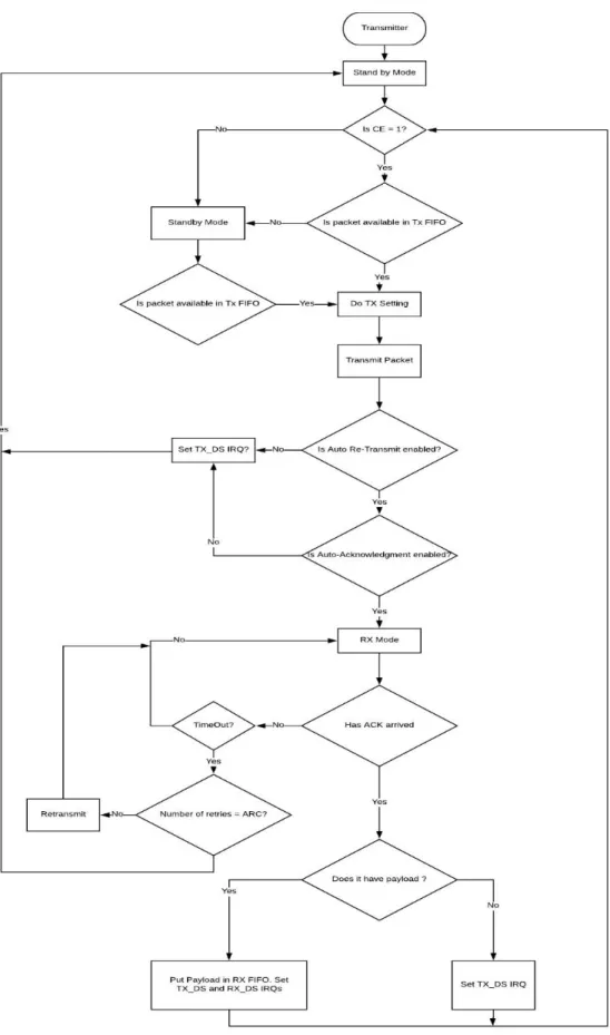
The nRF24L01+ has four operational modes. They are Power down, Standby, TX and RX modes. In power down mode, nRF24L01+ is disabled by using minimum current consumption. In this mode, the register values are still available, and the configurations of the module can be changed. If nRF24L01+ is not transmitting or receiving any packet, then it is recommended to put nRF24L01+ in the standby mode. The current consumption in the standby mode is less than the one in TX/RX mode.
The TX mode is an active mode where the transmission of packets is carried out. To put the nRF24L01+ in TX mode, the PRIM_RX bit should set low, CE should be set high for more than 10us, and there should be a payload in TX FIFO. The module will continue transmitting the packets as long as TX FIFO is refilled.
Similarly, the RX mode is an active mode where radio acts as a receiver. To enter RX mode from standby mode, PRIM_RX and CE bits are set high. When the receiver receives a packet then at first, it checks packet validity using CRC and matching address. If the packet is valid, then the received packet is sent to a vacant slot in the RX FIFOs. But if the RX FIFOs are full or the packet is invalid, the receiver discards the received packet.
The nRF24L01+ can operate on frequencies from 2.400 GHz to 2.525 GHz, and programming resolution of the RF channel frequency setting is 1 MHz [3]. The channel bandwidth in
nRf24L01+ depends upon the data rates. At 250 Kbps, the channel bandwidth is between 700 to 1000 kHz, at 1 Mbps the channel bandwidth can be between 900 to 1000 kHz, and at 2 Mbps the channel bandwidth is between 1800 kHz to 2000 kHz [3]. At 2 Mbps operation, there is channel overlapping between consecutive channels as the bandwidth is greater than the resolution of RF channel frequency setting. So, at 2 Mbps when using multiple channels, channel spacing must be
29
2 MHz or more than that to avoid overlapping between the channels. The RF channel frequency is set by RF_CH register using Equation 2 [3]:
(2) Similarly, the spectral efficiency of nRf24L01+ also varies with the data rates. Using the
Equation 1 the spectral efficiency at 250 Kbps is calculated to be between 0.25 bits/s/Hz to 0.35 bits/s/Hz, at 1Mbps the efficiency is between 1 bits/s/Hz to 1.111 bits/s/Hz and at 2 Mbps the efficiency is between 1 bit/s/Hz to 1.111 bits/s/Hz.
The nRF24L01+ module can work on any one of a number of channels (126) at one time, and the transmitter and the receiver must use the same channel to establish communication. In the same frequency channel, up to six different data pipes can be connected. But the communication can be done through only one data pipe at a time. It is not possible to have communication in more than one data pipes at the same time in the same frequency channel. The nRF24L01+ does not provide any channel noise reducing methods. If two different nRF24L01+ networks try to
communicate on the same channel there will an error during the transmission. It is recommended to use auto acknowledgment feature of nRF24L01+ so that the status of transmission can be monitored and thus lost packets can be retransmitted. It is also recommended to use a simple channel scanner to scan the channels in the environment to find a free channel before the communication is established. Hence, in the case of nRF24L01+, there is no effective noise reducing techniques. To prevent the interference from the outside environment, it is suggested to use the highest 25 channels because other 2.4 GHz radio waves like Wi-Fi uses most of the lower channels [4].
30
For this thesis, a radio module supporting the operation of the nRF24L01+ IC is used including a clock crystal, antenna, and matching circuit. This module allows easy interface of the
nRF24L01+ chip with a microcontroller SPI port. Some of the features of nRF24L01+ are:
Low cost, a single chip that works in 2.4 GHz ISM band.
Supports GFSK modulation. In GFSK modulation different frequencies are assigned to the carrier depending upon the bit that is transmitted. Let’s assume that the data consists of only two symbols 0 and 1. In GFSK, the information is conveyed by assigning a fixed carrier frequency for the duration of a 0 symbol and assigning another carrier frequency for the duration of a 1 symbol. In GFSK modulation, the waveform is passed through a Gaussian filter before the waveform goes into the modulator. This is done to smooth the transition between the values of impulses. The Gaussian filter limits the spectral width of the message signal and reduces the possibility of intersymbol interference in the signal.
Supports Multiceiver feature in which six different modules can be configured as receivers at the same time.
It has 126 channels points; thus, it can meet multipoint communications and channel hopping requirements. These channels points range from 0 to 125, and any channel among these 126 channels can be used for communication.
Since the link layer is fully integrated on the IC – writing code with instructions that control the nRF24L01+ is easy. The link layer in the nRF24L01+ handles the functions like data framing, physical addressing, error control and access control for the user. Figure 4 is the functional block diagram of nRF24L01+. It shows that a typical nRF24L01+ chip consists of RF transmitter and receiver, filters, modulator, demodulator, TX and RX FIFOs and Enhanced ShockBurst Baseband Engine.
31
Figure 4: Functional Block Diagram of nRF24L01+ [3]
The digital signals are converted in to radio waves using GFSK modulation. The data in nRF24L01+ is always put in packet format in the form of 0s and 1s. An embedded baseband protocol engine handles the packet communication between two modules. A bit in the configuration register is used to set the module in either transmit or receive mode. The Chip Enable (CE) bit is used to activate the transmitter or put the radio in receiving mode. If the RF module is configured as a receiver, then CE bit is set high to monitor the air and receive the packets. While if it is configured as a transmitter, then the CE bit is set high for about 10us to initiate the transmission and after that, it is set back to low. In this thesis, the transmitter receives data from MSP432 through SPI communication, formats it into proper packets, and transmits it to the receiver. While in the receiver side the received data is downloaded from FIFO, the error checking mechanism is performed, and at last, the user sent data or payload is extracted from the packet, and transmitted to MSP432 through SPI communication.
32
1.3.1.2.1 Enhanced ShockBurst Protocol
Enhanced ShockBurst is a packet based data link layer that features automatic packet assembly and timing, automatic acknowledgement and retransmissions of packets [3]. This feature enables the implementation of ultra-low power and high-performance communication. This feature improves the power efficiency for both bi-directional and uni-directional systems significantly, without adding any complexity. Some important features of Enhanced ShockBurst are given below:
It supports a star network topology with one Primary Receiver (PRX) and up to 6 Primary Transmitters (PTXs).
Provides both static and dynamic payload length features.
In dynamic payload length feature, a packet from 1 to 32 bytes can be transmitted to the receiver.
Supports bi directional data transfer between each PTX and the PRX.
Supports Packet acknowledgment (ACK) and automatic packet re transmission.
Have individual transmit (TX) and receive (RX) FIFOs for every pipe.
An Enhanced ShockBurst packet transaction is initiated when a packet is transmitted by the Primary Transmitter (PTX) and the transaction is completed when it receives an
acknowledgment packet (ACK packet) from the Primary Receiver (PRX). The PRX also has an option of transmitting a payload to PTX along with ACK packet, this feature is known as Acknowledgement with Payload. If the PTX does not receive the acknowledgment after initial transmission, it retransmits the packet until it receives back the acknowledgment from the
receiver. The total number of retransmissions attempts and the delay between the attempts can be configured in the register values. The receiver checks the validity of the received packet with the
33
help of a packet ID (PID) and cyclic redundancy check (CRC) fields. The PID is a 2-bit field which is used to detect if the received packet is a new or old one, while CRC is an error detection mechanism in the packet. The CRC is automatically calculated based on the packet content with the predefined polynomials. After receiving the packet, Enhanced ShockBurst performs CRC and checks its validity. If the CRC is valid, the received PID is compared with the previous received PID. If both PID fields are different, then the packet is considered a new one. But if the PID fields are same, then the receiver checks the CRC field. If the received CRC field is equal to the previous one, the newly received packet is defined as the previous packet and packet is discarded. But if the CRC field of the new packet is different than the previous one, the packet is considered a new one and is accepted.
Figure 5 is a basic auto acknowledgment communication timing diagram for the nRF24L01+. Figure 5 shows that after the packet is transmitted by the PTX and received by the PRX the ACK packet is transmitted from PRX to PTX. At first the PTX uploads the packet in the FIFO. Then, the packet is transmitted to the PRX and after 130us PTX changes its state to receiving state to receive the acknowledgement (ACK) packet from PRX. Similarly, when the PRX receives the packet, it downloads the packet and checks for error. If the received packet is a new one, then it sends the acknowledgment back to PTX. When PTX receives an acknowledgment, an interrupt is generated in MCU to indicate the successful transmission of data.
34
Figure 5: Data Transfer Timing Diagram in ShockBurst [3]
Static and Dynamic Payload Length
Enhanced ShockBurst provides two different alternatives to handle payload length. The payload in a whole transmitted packet is the actual user sent data. In normal condition, the nRF24L01+ transmits the data using static payload length feature. In static payload length configuration, all packets transmitted between a transmitter and a receiver always has the same payload length that is 32 bytes. But with dynamic payload length feature, the transmitter can send packets with variable payload lengths to the receiver. So that means that for a system with different payload lengths it is not necessary to scale the payload length to the longest payload size (32 bytes), thus in dynamic payload length feature, the length of the payload is equal to the length of the actual user sent data. The dynamic payload length decreases the transmission time in the nRF24L01+.
Auto Acknowledgment
Auto acknowledgment is a function that allows the receiver to automatically send the
acknowledgment (ACK) packet to the transmitter after it has received and verified the data. The auto acknowledgment function reduces the load of the system MCU and also reduces cost and
35
average current consumption. An ACK packet from the receiver can also contain payload from PRX to PTX. This feature is known as acknowledgment with payload feature. To use this
feature, the Dynamic Payload Length should be enabled. The MCU on the PRX side uploads the payload by clocking it into the TX FIFO. This payload stays in the TX FIFO (PRX) until a new packet is received from PTX. After a new packet is received this payload is transmitted with the new acknowledgment packet. Figure 6 shows the TX FIFO in receiver side when the
acknowledgment with payload feature is enabled. From Figure 6 it can be observed that at a time, nRF24L01+ can have up to three ACK payloads pending in the TX FIFO.
Figure 6: TX FIFO (PRX) with Pending Payloads [3]
Multiceiver
Multiceiver is a feature used in RX mode that allows six different TX to connect with it using a set of six parallel data pipes with unique addresses. This feature allows nRF24L01+ to
implement the Star Network protocol. A data pipe is a logical channel in the physical RF channel and has its own physical address. All data pipes addresses are searched at the same time, but only one data pipe can receive a packet a time. Figure 7shows a Multiceiver network in nRF24L01+.
36
Figure 7: Data Pipe Addressing in Multiceiver [3]
The main characteristic of Multiceiver capability is having up to 6 radio communication
channels open in a receiving mode simultaneously. The first task is to open six reading pipes in the primary receiver hub (PRX). This PRX acts as the central hub in the network. All the data communication is done through this hub. Now each PTX or peripheral node links to one of these opened pipes. These PTX nodes transmit and receive the packets using this pipe. So, when the data is being transmitted from PRX to PTX, the writing address of PRX should match the address of PTX it wants to transfer. The data pipe addressing in Multiceiver network has some specific rules. Data pipe 0 always has a unique 5-byte address while data pipe 1-5 share the four most significant address bytes. And also, the write address on the PRX side should match the PTX address. Another one important thing to remember is that when transmitting from the PRX to PTX, the write address should always be opened in pipe 0. For example, let us suppose that there are 3 PTXs, and they are opened in pipe 0, 1 and 2 in PRX respectively. Now if the data has to be transmitted from the PTX 1 to PTX 3, then the first transmission is done from the
37
PTX1 to PRX through data pipe 0. During the second transmission from the PRX to PTX 2, the write address from central hub (PRX) should be opened in pipe 0 even though the PTX 2 was opened initially in pipe 2 in PRX.
1.3.1.3ESP32
ESP32 is a single 2.4 GHz Wi-Fi and Bluetooth combo chip designed with the TSMC ultra-lower-power 40nm technology [5]. It is a dual-core system with two Harvard Architecture Xtensa LX6 CPUs. This device is specifically designed for mobile, wearable electronics and the IoT applications. Figure 8 shows the general block diagram of ESP32. The clock frequency of ESP32 can be up to 240 MHz. There are different modules of ESP32 available in the market. In this thesis, the ESP-WROOM-32 module on the ESP-DevKitC board [5] is used to realize the BLE and ESP-Now protocols. ESP32 supports classical Bluetooth, BLE and Wi-Fi standard wireless protocols. Beside these standard protocols, ESP32 also supports ESP-Now, which is a nonstandard wireless protocol used for communicating Wi-Fi enabled devices without the use of a router. The ESP32 also supports RTC and cryptographic hardware accelerators. None of these securities and RTC features has been studied in this thesis.
38
Figure 8: Functional Block Diagram of ESP32 [5]
1.3.1.3.1 Bluetooth Low Energy (BLE)
Bluetooth Low energy is a wireless personal area network technology designed by the Bluetooth Special Interest Group. BLE is an updated version of classical Bluetooth aimed at reducing the power consumption and cost while maintaining similar communication range. The main difference between the regular (classical) Bluetooth and BLE is the power consumption and message size. The classical or regular Bluetooth was designed to handle large data size at high power consumption. But BLE is used for those applications which do not need to exchange large amounts of data, thus have low power consumption. The application throughput and
communication set up time for regular Bluetooth is higher compared to the BLE. Thus, BLE is generally suited for those applications which require the periodic transfer of data and not the
39
continuous data stream, while classical Bluetooth is suitable for later one. Also, the classical Bluetooth has 79 channels in the frequency band whereas BLE consists of only 40 channels in the frequency band.
The Bluetooth Low Energy consists of 40 channels from 2.402 GHz to 2.480 GHz. Among 40 channels, three are used as advertising channels, and 37 are used as data channels. These channels have center frequencies at where k = 0 to 39 [6]. The three channels from 37 to 39 are used for advertising packets whereas the remaining channels are used to exchange data packets in the connections. Each channel has a bandwidth of 2 MHz.
Figure 9 shows the BLE frequency channels. The first channel, 37, is assigned at 2402 MHz, while the last one, the 39is centered at 2480 MHz. The maximum data rate of BLE in ESP32 is up to 700 kbps [7] . So, using Equation 1 the maximum spectral efficiency that can be achieved in ESP32 BLE is 0.35 bits/s/Hz.
Figure 9: BLE Frequency Channels [6]
In the BLE, two devices use a shared physical channel for communication. In BLE specification, for devices to communicate with each other they are tuned to same RF frequency at a time [8]. If there are multiple BLE devices tuned into the same frequency, then there is a possibility of
40
channel collision among devices. To mitigate this issue, BLE uses a randomly generated Access Address to identify the link between the devices.
The data channel of BLE is characterized by a pseudo-random sequence of PHY channel as shown in Figure 9. In addition to this, it is also characterized by the three additional parameters provided by master. A master is the BLE device in the network that initiates the connection and handles almost every aspects of the connection. Either a server or client can act as master after the connection is established. One of the parameters is the channel map that indicates the set of physical channels used. The channel map is a sequence of 40 bits where three most significant bits are reserved for advertising channels and rest 37 bits corresponding to the data channels. If in a BLE network, channel x is used, then the bit corresponding to that data channel in channel map is set to 1 [9]. The next parameter is a hop, whose value ranges from 5 to 16 and is set when the connection is created. The data channel in BLE is divided into connection events where each event corresponds to a physical frequency. The connection event in the ESP32 BLE occurs when a client is connected to the server. The data exchanging occurs between BLE devices over these dedicated frequency hopping data channels [10]. The connection will stay on the same channel during the interval of connection events. During the new connection event, the master switches to a new channel.
The maximum number of slaves that can connect to a master depends upon the software and hardware characteristics, such as the amount of memory on BLE IC, the type of communications between master and slave, and some connection parameters such as connInterval [6]. If a master wants to connect to a new slave, then it has to reset its RF frequency since different slaves belong to different piconets with a master in common. For this reason, the connInterval
41
two consecutive connection events. It is always the multiple of 1.25ms in the range of 7.5ms to 4.0s [6]. This interval can be set in Generic Access Profile (GAP) parameters. The master needs time to switch between the different slaves without overlapping their respective connection events. Thus, it is possible to have two overlapping communications in BLE if connection interval is not properly set. In this case, there will be a loss of data during communication. Hence, if a master needs to connect with a lot of slaves, then the connection event of each connection has to be decreased. At present, theoretically, a maximum number of 7 slaves can connect to the master in the latest version of ESP32 BLE [11].
An adaptive frequency mechanism is used in BLE to reduce the interference from other technologies. The hopping pattern in BLE is unique and is derived from the clock and BLE device address of master. Adaptive frequency hopping is the type of hopping process in which channel conditions are constantly monitored to identify the occupied or low quality channels. This allows the Bluetooth to identify the fixed sources of interference and exclude them from the list of available channels. Common metrics that are used to determine the quality on RX channel are Received Signal Strength Indication, Bit Error Rate, and Signal to Noise Ratio [12].
A BLE device can communicate to another device in two ways: Broadcasting and Connection.
Broadcasting
Broadcasting is the method in which a device sends the data out to all listening devices. The broadcaster sends the non-connectable advertising packets periodically to any listening device, while the observer continuously scans the surrounding to receive the packet. Non- connectable advertising packets mean that the central device cannot connect to the peripheral device. The non-connectable advertising packet is used only for broadcasting, and the device transmits the internally stored information in this type. This advertisement type is used when the device does
42
not want to connect to any devices but wants only to broadcast the internally stored information to other peripheral devices. In this method, the observer passively listens to BLE devices in its surrounding. After it receives the advertising packets from the broadcaster, it processes the data from the received packets. A device can transmit data to more than one peer at a time by only using non-connectable advertisings [13]. Figure 10 shows a network where a device is
broadcasting the non-connectable advertising packets to the observer devices.
Figure 10: BLE Broadcast Topology [13]
Connection
In the connection method, the link is permanent that means a connection is established between two devices and periodical data exchanges occur between them unless they are disconnected. In this thesis, the BLE devices are communicating with each other using this method. The master scans the area for connectable advertising packets. The packets are connectable or
non-connectable based on the value of the packet data unit or PDU field in the BLE advertising packets. The connectable advertising packets type allows the device to both transmit and receive the information. This advertising packet can be both directed and undirected. The direct
43
method is used when a device needs to connect quickly with another device. The directed
advertisements have an intended receiving device, while undirected advertisements do not have a specific intended receiver.
The central device initiates the connection in this topology. It commands almost every aspect of the connection. It acts as an initiator in the SMP level, and thus commands the beginning of all SMP procedures [13]. The SMP stands for Security Manager Protocol and is responsible for functions like device authentication, authorization, integrity, etc. In this method, the pairing device is not allowed to make any decisions regarding the connection or pairing. The pairing device sits there advertising the packets and accepts all the incoming configurations about the connection from the central device. The peripheral always follows the center’s timing and commands to establish the connection. Figure 11 shows a connectable advertising packets network where the central device is establishing the connections with the peripheral devices which are advertising the connectable advertising packets in the network. Unlike in broadcasting, Figure 11 shows that communication is both ways in connectable advertising packet method.
44
BLE Architecture
BLE, like many other wireless technologies has some protocol layers, and each layer has its purpose and plays a significant role in BLE communication. The main three building blocks of a BLE device are Application, Host, and Controller. Figure 12 shows the general architecture of BLE.
Application
The application layer is the top most layer and is responsible for user interface and data handling logic. The architecture of this layer highly depends upon the project developed with BLE. Host
The host layer in BLE provides information resources, services, and applications to the user or other nodes. It consists of the upper layers of the Bluetooth protocol stack. This layer consists of many sub layers as shown in Figure 12.
Generic Access Profile (GAP)
This layer controls the advertising and connections between the devices. It specifies how devices will implement control procedures such as discovery, connection, etc. The discovery procedure handles the discovery of services, characteristics, and attributes on the remote GATT server on the connected device. The remote GATT server means GATT layer of the connected server device. The main focus of this layer is to control the roles and interaction between devices.
Generic Attribute Profile (GATT)
This layer defines how the data is organized and exchanged between devices. The data in GATT is organized in Services, which contains one or more characteristics. Each
45
characteristic is a combination of user data along with the descriptive information about the characteristic itself. GATT services are organized in GATT profiles. Each service and characteristic has their 16-bit UUID which distinguish it from other services and characteristics respectively.
Security Manager Protocol (SMP): It defines the procedures and behaviors to manage pairing, authentication, and encryption between the devices.
Logical Link Control Adaptation Protocol (L2CAP): It is mainly responsible for two tasks:
- It takes multiple data from upper layers and encapsulates them into the standard BLE packet format and vice versa.
- It also breaks the large packets from upper layers into chunks that fit into the maximum payload size and also recombines the fragmented chunk of received data into a single large packet.
Controller
Host Controller Interface (HCI): It implements commands, event, and data interface that allow upper layers such as GAP to access link layer.
Link Layer (LL): This layer manages the physical BLE connection between devices.
Physical Layer (PHY): This layer contains the circuitry that manages the modulating and demodulating analog signals and transforming into digital symbols. For this BLE uses a technique known as frequency hopping spread spectrum. In frequency hopping spread spectrum, the carrier frequency is rapidly switched among many frequency channels. The available frequency channel is sub divided into many sub-frequencies. Signals rapidly hop among these in a predetermined order to transmit the radio signals [14].
46
Figure 12: BLE Architecture [14]
The Generic Access Profile (GAP) and Generic Attribute (GAAT) are the most two important layers of BLE Architecture when establishing the communication between client and server in ESP32 BLE, so more detailed description of these two layers is given below:
Generic Access Profile (GAP)
The GAP is responsible for the discovery process, device management and the establishment of device connection between BLE devices. The BLE GAP is implemented in the form of API calls and Event returns [11]. Figure 13 shows the state transitions among GAP roles. The four main responsibilities of GAP for a BLE device are:
Broadcaster: A broadcaster is a device which sends the advertising packets so that it can be discovered by the observers. This device is only responsible for broadcasting not connecting.
Observer: An observer is a device that scans for broadcasters. This device can only send scan requests.
47
Peripheral: It is a device that advertises the connecting advertising packets. This device becomes a slave once the connection is made. In this thesis, the client was configured in this role.
Central: A central is a device that initiates connections to peripherals and becomes master once the connection is made. In this thesis, the server was configured as central.
Figure 13: Status Transitions among GAPs [11]
BLE Modes
Connectable Scannable Undirected Mode:
In Connectable Scannable Undirected mode, a device can be discovered by and
connected to any device. In this mode, the local device replies with a scan response, when a peer device sends a scan request. The packet format for this mode contains 6 bytes of the broadcast address and 0 – 31 bytes of broadcast packet data. In this thesis, ESP32 modules were configured in this mode.
High Duty Cycle Directed Mode and Connectable Low Duty Cycle Directed Mode: In this mode, the broadcaster can only connect to the designated devices. The packet
48
contains 6 bytes of the broadcasting device’s address and 6 bytes of the receiving device’s address.
Scannable Undirected Mode: In the Scannable Undirected mode, a device can be discovered by any other device, but it cannot get connected to it. The packet format for this mode is similar to Connectable Scannable Undirected Mode.
Non-connectable Undirected Mode: In this mode, a device can be discovered by any device, but neither can be connected to or scanned by any other device. An unscannable device is a device that will not reply with any scan response to the peer device. The packet contains 6 bytes of broadcast address and 0 – 31 bytes of broadcast packet data.
Generic Attribute [GATT]
The data inside the BLE architecture are in the form of Attributes which consist of four basic elements:
Attribute Handler: This helps us to locate any attribute, like using an address to locate data in the memory.
Attribute Type: This element identifies the type of information contained by the data. A 16-bit or 128-bit number, known as UUID is used to identify the type of attribute.
Attribute value: The attribute value is the key information of each attribute. The length of the attribute types can be fixed or variable.
Attribute Permission: This element determines whether the information contained by the attribute can only be read or written.
A server can send data to the client in two ways. The server can send data by using an Indication or Notification, and a client can also obtain data from the server by initiating a Read Request. A client sends data to a server by writing the data to the characteristic of the server. The Write
49
Request and Write Command are used to do write operation in the server. However, a Write Response is only promoted when a Write Request is used [11]. Indication is similar to Write Request and Notification is similar to Write Command. Figure 14 shows the common operations that happen between a Server and a Client during data exchange.
Figure 14: Common Operations between a Server and a Client [11]
The Attribute gives the minimum data storage unit in the BLE architecture, while the GATT defines how to represent the data set using its attributes and descriptors, how to aggregate similar data into a service, and how to find out what services and data a peer device owns [11]. GATT introduces the concept of Characteristics about the information. A characteristic can be
categorized into three basic parts:
Characteristic Declaration: It is the beginning of the characteristics and informs the peer device that the content followed by it is the characteristic value. The write and read properties of a data set are also included in the declaration.
Characteristic Value: It is the main part of a characteristic which contains the most important information of a characteristic.
Descriptor: Descriptors further describe the characteristic. A characteristic can have single, multiple or no descriptors.
50
In BLE, the similar functions are grouped together in the services. Figure 15 shows the way services, characteristics and descriptors are defined in the attribute table. Figure 15 indicates that a service can have one or more characteristics and each characteristic includes zero or multiple descriptors.
Figure 15: The Definition Table of service [11]
1.3.1.3.2 ESP-Now
ESP- Now is a proprietary wireless technology developed by Espressif systems that can be implemented in ESP32 development board. ESP-Now is a Fi direct application. Like in Wi-Fi direct, the AP or client roles are dynamic in the ESP-Now. ESP-Now does not require access point or router to establish the connection. It uses the concept of soft-AP to negotiate the roles of the pair to pair devices when they discover each other.
ESP-Now uses the same frequency and channels as Wi-Fi does. On the 2.4 GHz band in North America, there are 11 channels of 22 MHz present in a Wi-Fi frequency band [15]. Figure 16 shows the Wi-Fi channels on the frequency band. Some or all channels from 12 to 14 are allowed in some other countries. The center frequencies of channels from 1-13 differ by only 5 MHz.
51
Hence, there are only three non-overlapping channels in a Wi-Fi frequency band. The bandwidth of the single channel in Wi-Fi is 22 MHz. The maximum throughput that can be achieved in ESP32 Wi-Fi channel is 30 Mbit/s [16]. Thus, using Equation 1 the spectral efficiency of ESP-Now is 1.36 bits/s/Hz.
Figure 16: Wi-Fi Channels on the 2.4 GHz Frequency band [15]
ESP32 Wi-Fi driver supports IEEE-802.11b and IEEE-802.11g standards to configure the protocol mode [16]. IEEE-802.11b/g operate in the 2.4 GHz frequency band. This frequency band contains only three non-overlapping channels for the communication, and it is
recommended to use these channels for communication. But nowadays, the density of nodes in the available frequency band is very high, and there is always some risk of interference from other radio networks.
IEEE 802.11 has provided two operating modes: Distributed Coordination Function (DCF) and Point Coordination Function (PCF) to coordinate communication in the network [17]. In the DCF operating mode, the channel claim process begins when a station senses the channel to determine whether it is free or not. For this DCF utilizes two techniques: DCF Inter-frame Space
(DIFS) and the backoff algorithm [18]. DIFS is the time period where a channel should be idle before transmission from the station can begin. If the medium is sensed busy for that time period, then the transmission is delayed until the channel is idle again. In this case, a backoff interval
52
(BI) is randomly selected. The BI interval is in between a minimum contention period and a maximum contention period. The difference between these periods is known as the contention window (CW) [18]. There still is a chance of collision happening if two or more stations select the same backoff interval for the channel. This problem is mitigated by doubling CW every time a collision occurs [18]. When a station enters the backoff, the station monitors the channel as before. This backoff timer is decreased as long as the channel is idle. When the transmission is in progress, this timer is stopped and reactivated when the channel becomes idle again. Point
Coordination Function (PCF) uses Access Point to coordinate the communication within the network. The AP waits for the PCF Inter-frame Space (PIFS) duration to grasp the channel. PIFS duration is less than DIFS duration. Thus this method always has the priority to access the
channel. PCF is not that common and is only implemented in some hardwares since it is not part of Wi-Fi Alliance’s interoperability standard.
There are mainly two kinds of interference that can occur in a Wi-Fi channel: co-channel Interference (CCI) and adjacent channel interference (ACI). The CCI occurs when transmission occurs on the same frequency in the same area. The ACI occurs when transmissions are sent on the adjacent or partially overlapping channels. These interferences are decreased by different operating modes of IEEE 802.11 MAC procedure. Besides these modes, the IEEE 802.11 standard has also defined the transmit spectrum mask intended to limit the energy of the transmitted signal. This method is used to limit the invasion of the signal on adjacent channels around the central frequency. The IEEE 802.11 standard also says that bandpass filters should be applied in both transmitter and receiver, to isolate the desired signal before transmission and reception [17]. This method decreases the energy received from another adjacent channel. In ESP32 this filter can be enabled or disabled by using the channel_filter_en parameter.
53
One of the limitations of ESP32 is that it is limited to only one channel at a time. So, when there are soft-AP and station mode, the soft-AP device always adjusts its channel to the channel of ESP32 station device.
A wireless router or any other access point can handle up to 250 devices at once. This is just a theoretical value, practically it is not feasible to connect that many devices to a single access point at once. If there are many clients accessing the same access point, then there always is a risk of data collision and interference. Thus, normally many routers are configured in such a way that the maximum number of devices that can be connected is 50 [19]. Whereas, the maximum number of peers that can be supported by ESP-Now is less than 20; this includes both encrypted and unencrypted peers [16].
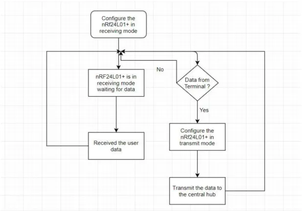
ESP-Now requires an initial pairing between the devices. Once pairing is established the
connection is persistent peer-to-peer. In an ESP-Now communication, the wireless module acting as Master or Controller uses MAC address to pair with the slave device. A MAC address is a unique identifier of a network hardware interface which is used for communicating on the physical network. The MAC address of the slave can be set in the program itself using ESP32’s Wi-Fi attributes. Further details on the MAC address are described in section 3.2.3. Up to 20 peer devices can be as paired devices.
Once the devices are paired with each other, the data can be sent from master to slave or vice versa. ESP-Now uses callback functions to indicate the transmission and reception of the data. A callback function is a function that is passed into another function as an argument, which is then invoked inside the outer function when some event or routine occurs. The call back functions used in ESP-Now for transmission and reception are OnDataSent() and OnDataRecv(). These functions are passed as an argument into register functions – esp_now_register_send_cb() and
![Figure 8: Functional Block Diagram of ESP32 [5]](https://thumb-us.123doks.com/thumbv2/123dok_us/9020339.2799882/38.918.217.724.127.548/figure-functional-block-diagram-esp.webp)