EUROCODES
Background and Applications
“Dissemination of information for training” workshop
18-20 February 2008
Brussels
EN 1991
Eurocode 1: Actions on structures
Organised by
European Commission: DG Enterprise and Industry, Joint Research Centre
with the support of
Tuesday, February 19 – Palais des Académies
EN 1991 - Eurocode 1: Actions on structures
Baron Lacquet room
9:00-9:10
Introduction by chairman
H. Gulvanessian
CEN/TC250
9:10-9:45
Introduction to EN 1991
N. Malakatas
Ministry of Environment, Physical
Planning & Public Works of Greece
9:45-10:30
EN 1991-1-1
N. Malakatas
Ministry of Environment, Physical
Planning & Public Works of Greece
10:30-11:00
Coffee
11:00-11:45
EN 1991-1-3
P. Formichi
University of Pisa
11:45-12:45
EN 1991-1-4
S. O. Hansen
Svend Ole Hansen ApS
12:45-14:00
Lunch
14:00-14:35
EN 1991-1-5
M. Holicky
Czech Technical University in Prague
14:35-15:10
EN 1991-1-6
P. Formichi
University of Pisa
15:10-15:40
Coffee
15:40-16:30
EN 1991-1-7
A. Vrouwenvelder
TNO
16:30-17:30
EN 1991-2
J.-A. Calgaro
CGPC, CEN/TC250 Chairman
M. Tschumi
SBB-CFF-FFS
17:30-18:00
Discussion and close
All workshop material will be available at
http://eurocodes.jrc.ec.europa.eu
INTRODUCTION TO EN 1991
N. Malakatas
Ministry of Environment, Physical Planning &
Public Works of Greece
1
Introduction to EN 1991
(Eurocode 1: Actions on structures)
Dr-Ing. Nikolaos E. Malakatas
Head of Department - Ministry of Environment,
Planning and Public Works - GREECE
Chairman of CEN/TC250/SC1
LINKS BETWEEN THE EUROCODES
EN 1990
EN 1991
EN 1992
EN 1993 EN 1994
EN 1995 EN 1996 EN 1999
EN 1998
EN 1997
Actions on
structures
Design and detailing
Geotechnical
and Seismic
design
Structural safety,
serviceability and
durability
Past and future of the EN 1991
(and the other Eurocodes)
Time Period
Phase
CEN/TC250
Chairman
CEN/TC250/
Chairman
SC1
1980 ’s
preparation under
Technical
EC Steering
Committee
1990 –
1998/2000
ENV (under CEN)
Dr Breitschaft
(until 1993)
Dr Lazenby
Dr Menzies
1998/2000 –
2007
EN (under CEN)
Bossenmeyer
Prof.
Gulvanessian
Prof.
2008 - ?
•
Implementation
•
Maintenance
•
Harmonization
•
Dissemination
•
Further
development
Prof. Calgaro
Dr Malakatas
Parts and implementation of EN 1991
Part of Eurocode 1
:
Actions on structures
Title (Subject)
Issued
EN 1991-1-1
General actions – Densities,
self-weight, imposed loads for buildings
April 2002
EN 1991-1-2
General actions – Actions on structures
exposed to fire
November 2002
EN 1991-1-3
General actions – Snow loads
July 2003
EN 1991-1-4
General actions – Wind actions
April 2005
EN 1991-1-5
General actions – Thermal actions
November 2003
EN 1991-1-6
General actions – Actions during
execution
June 2005
EN 1991-1-7
General actions – Accidental actions
July 2006
EN 1991-2
Traffic loads on bridges
September
2003
EN 1991-3
Actions induced by cranes and
machinery
July 2006
EN 1991-4
Silos and tanks
May 2006
Partitioning of the NDPs
among the Eurocodes
Types of NDPs in the Eurocodes
Type 1: Value (s) of (a) parameter (s).
Type 2: Reference to some set of values – table (s).
Type 3: Acceptance of the recommended procedure, choice of calculation approach, when alternatives are given, or
introduction of a new procedure.
Type 4: Country specific data (geographical, climatic, etc.).
Type 5: Optional National chart (s) or table (s) of a parameter.
Type 6: Diagram (s).
Type 7: References to non-contradictory complementary information to assist the user to apply the Eurocodes.
Type 8: Decisions on the application of informative annexes.
Type 9: Provision of further, more detailed information.
Type 10: Reference to information
4 0 0 16 3 50 1 1 15 2 3 2 4 7 10 4 2 9 18 0 10 0 2 0 0 3 0 0 4 0 0 5 0 0 6 0 0 T y p e 1 T y p e 2 Ty pe 3 T y p e 4 Ty pe 5 T y p e 6 Ty pe 7 T y p e 8 T y pe 9 T y p e 10
2
EN 1991-1-1: Densities, self-weight,
imposed loads for buildings
z
Forward
z
Section 1
– General
z
Section 2
– Classification of actions
z
Section 3
– Design situations
z
Section 4
– Densities of construction and stored materials
z
Section 5
– Self-weight of construction works
z
Section 6
– Imposed loads on buildings
z
Annex A (informative)
– Tables for nominal density of construction
materials, and nominal density and angles of repose for stored
materials.
z
Annex B (informative)
– Vehicle barriers and parapets for car
parks
EN 1991-1-2: Actions on structures
exposed to fire
z
Forward
z
Section 1
– General
z
Section 2
– Structural Fire design procedure
z
Section 3
– Thermal actions for temperature analysis
z
Section 4
– Mechanical actions for temperature analysis
z
Annex A (informative)
– Parametric temperature-time curves
z
Annex B (informative)
– Thermal actions for external members –
Simplified calculation method
z
Annex C (informative)
– Localised fires
z
Annex D (informative)
– Advanced fire models
z
Annex E (informative)
– Fire load densities
z
Annex F (informative)
– Equivalent time of fire exposure
z
Annex G (informative)
– Configuration factor
EN 1991-1-2: Actions on structures
exposed to fire ( cont.)
EN 1991-1-3: Snow loads
z
Forward
z
Section 1
– General
z
Section 2
– Classification of actions
z
Section 3
– Design situations
z
Section 4
– Snow load on the ground
z
Section 5
– Snow load on roofs
z
Section 6
– Local effects
EN 1991-1-3: Snow loads (cont.)
z
Annex A
(normative)
– Design situations and load
arrangements to be used for different locations
z
Annex B
(normative)
– Snow load shape coefficients for
exceptional snow drifts
z
Annex C (informative)
– European Ground Snow Load
Maps
z
Annex D (informative)
– Adjustment of the ground snow
load according to the return period
z
Annex E (informative)
– Bulk weight density of snow
3
EN 1991-1-4: Wind actions
z
Forward
z
Section 1
– General
z
Section 2
– Design situations
z
Section 3
– Modelling of wind actions
z
Section 4
– Wind velocity and velocity pressure
z
Section 5
– Wind actions
z
Section 6
– Structural factor
c
s
c
d
z
Section 7
– Pressure and force coefficients
z
Section 8
– Wind actions on bridges
EN 1991-1-4: Wind actions (cont.)
EN 1991-1-4: Wind actions (cont.)
EN 1991-1-4: Wind actions (cont.)
z
Annex A (informative)
– Terrain effects
z
Annex B (informative)
– Procedure 1 for determining the
structural factor
c
s
c
d
z
Annex C (informative)
– Procedure 2 for determining the
structural factor
c
s
c
d
z
Annex D (informative)
–
c
s
c
d
values for different types
of structures
z
Annex E (informative)
– Vortex shedding and aeroelastic
instabilities
z
Annex F (informative)
– Dynamic characteristics of
structures
EN 1991-1-5: Thermal actions
z
Forward
z
Section 1
– General
z
Section 2
– Classification of actions
z
Section 3
– Design situations
z
Section 4
– Representation of actions
z
Section 5
– Temperature changes in buildings
z
Section 6
– Temperature changes in bridges
z
Section 7
– Temperature changes in industrial chimneys,
pipelines, silos, tanks and cooling towers
EN 1991-1-5: Thermal actions (cont.)
z
Annex A
(normative)
– Isotherms of national minimum
and maximum shade air temperatures.
z
Annex B
(normative)
– Temperature differences for
various surfacing depths
z
Annex C (informative) –
Coefficients of linear expansion
z
Annex D (informative) –
Temperature profiles in
4
EN 1991-1-6: Actions during execution
z
Forward
z
Section 1
– General
z
Section 2
– Classification of actions
z
Section 3
– Design situations and limit states
z
Section 4
– Representation of actions
z
Annex A1
(normative)
– Supplementary rules for
buildings
z
Annex A2
(normative)
– Supplementary rules for bridges
z
Annex B (informative)
– Actions on structures during
alteration, reconstruction or demolition
EN 1991-1-7: Accidental actions
z
Forward
z
Section 1
– General
z
Section 2
– Classification of actions
z
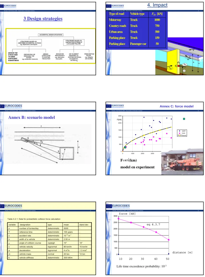
Section 3
– Design situations
z
Section 4
– Impact
z
Section 5
– Internal explosions
z
Annex A (informative)
– Design for consequences of localised
failure in buildings from an unspecified cause
z
Annex B (informative)
– Information on risk assessment
z
Annex C (informative)
– Dynamic design for impact
z
Annex D (informative)
– Internal explosions
- D.1 :
Dust explosions in rooms, vessels and bunkers
- D.2 :
Natural gas explosions
- D.3 :
Explosions in road and rail tunnels
EN 1991-1-7: Accidental actions
EN 1991-1-7: Accidental actions
EN 1991-2: Traffic loads on bridges
z
Forward
z
Section 1
– General
z
Section 2
– Classification of actions
z
Section 3
– Design situations
z
Section 4
– Road traffic actions and other actions
specifically for road bridges
z
Section 5
– Actions on footways, cycle tracks and
footbridges
z
Section 6
– Traffic actions and other actions specifically
for railway bridges
EN 1991-2: Traffic loads on bridges (cont.)
z
Annex A (informative)
– Models of special vehicles for road
bridges
z
Annex B (informative)
– Fatigue life assessment for road bridges
assessment method based on recorded traffic
z
Annex C
(normative)
– Dynamic factors 1 +
φ
for real trains
z
Annex D
(normative)
– Basis for the fatigue assessment of railway
structures
z
Annex E (informative)
– Limits of validity of load model HSLM and
the selection of the critical universal train from HSLM-A
z
Annex F (informative)
– Criteria to be satisfied if a dynamic
analysis is not required
z
Annex G (informative)
– Method for determining the combined
response of a structure and track to variable actions
z
Annex F (informative)
– Load models for rail traffic loads in
transient design situations
5
EN 1991-2: Traffic loads on bridges (cont.)
EN 1991-2: Traffic loads on bridges (cont.)
EN 1991-2: Traffic loads on bridges (cont.)
EN 1991-2: Traffic loads on bridges (cont.)
EN 1991-3: Actions induced
by cranes and machinery
z
Forward
z
Section 1
– General
z
Section 2
– Actions induced by hoists and cranes on
runway beams
z
Section 3
– Actions induced by machinery
z
Annex A
(normative)
– Basis of design - Supplementary
clauses to EN 1990 for runway beams loaded by cranes
z
Annex B (informative)
– Guidance for crane
classification for fatigue
EN 1991-4: Silos and tanks
z
Forward
z
Section 1
– General
z
Section 2
– Representation an classification of actions
z
Section 3
– Design situations
z
Section 4
– Properties of particulate solids
z
Section 5
– Loads on the vertical walls of silos
z
Section 6
– Loads on silo hoppers and silo bottoms
6
EN 1991-4: Silos and tanks (cont.)
z
Annex A
(normative)
– Basis of design – Supplementary
paragraphs to EN 1990 for silos and tanks
z
Annex B
(normative)
– Partial factors and combinations of actions
on tanks
z
Annex C (informative)
– Measurements of properties of solids for
silo load evaluation
z
Annex D (informative)
– Evaluation of properties of solids for silo
load evaluation
z
Annex E (informative)
– Values of the properties of particulate
solids
z
Annex F (informative)
– Flow pattern determination
z
Annex G (informative)
– Alternative rules for pressures in hoppers
z
Annex H (informative)
– Actions due to dust explosions
EN 1991-4: Silos and tanks (cont.)
Background Documents
and other supporting material
z
Almost all Eurocodes represent the state-of-the-art in the
respective scientific and technical field at the time of their
drafting
z
The scientific and technical basis of EN 1991 included mainly :
- the systematic review of the existing relevant national codes
and practices
- consideration of relevant international standards (e.g. ISO
Standards) or codes (e.g. JCSS Model Codes)
- recent (prenormative) research results (e.g. European Snow
Map)
- calibration of load models based on probabilistic approaches
and appropriate measurements (e.g. traffic loads for road
bridges)
Background Documents and
other supporting material (cont.)
- Well-established relevant international literature
z
Strictly speaking, as Background Documents (BD) are considered
all of the aforementioned material that has been taken into
account by the relevant Project Team, during the drafting of the
Eurocodes.
z
All other relevant material, including literature, workshops and
seminars, handbooks, guides and books or articles, are
considered to be additional information and supporting material.
A typical example are the 5 handbooks prepared in the framework
of a Leonardo Da Vinci European Project (Handbook 3 is very
closely linked to EN 1991, since it is dedicated to “Action Effects
on Buildings”, and Handbook 4 is dedicated to the “Design of
Bridges”). This material is accessible on the Eurocodes website.
Background Documents and
other supporting material (cont.)
z
The uploading of the Background Documents (BD) for
EN 1991 is under way by the Secretary of EN/TC250/SC1.
Until recently BD have been uploaded for the following
Parts of EN 1991 :
- EN 1991-1-1
- EN 1991-1-2
- EN 1991-1-3
- EN 1991-1-6
- EN 1991-1-7
and Handbooks 1 to 5
z
Additional information can also be found in the relevant
websites, e.g.
http://eurocodes.jrc.ec.europa.eu
, and
other links (e.g. NSO et al.)
Present and Future of the EN 1991
z
Finalising the preparation of some
Corrigenda
(target
date June 2008)
z
Detecting the eventual need for some
Amendments
(target date June 2009)
z
On national level : Full implementation. Several
countries have already issued their national standard
EN 1991, but uploading of the NDPs in the ad-hoc data
base of JRC Ispra goes on at a slow pace
z
Prospects for the future :
- Extending the snow map and other climatic data to
cover the new EU Member States
- Including eventually the ISO Standards on “Waves
and Currents” and on “Atmospheric Icing”
7
THANK YOU FOR
THANK YOU FOR
YOUR ATTENTION
EN 1991-1-1
N. Malakatas
Ministry of Environment, Physical Planning &
Public Works of Greece
1
Eurocode 1: Actions on structures –
Part 1-1: General actions - Densities,
self-weight, imposed loads for buildings
Dr-Ing. Nikolaos E. Malakatas
Head of Department - Ministry of Environment,
Planning and Public Works - GREECE
Chairman of CEN/TC250/SC1
Use of EN 1991-1-1
•
Gives design guidance and actions for the structural design
of buildings and civil engineering works, including the
following aspects :
- densities of construction materials and stored materials
- self-weight of construction elements, and
- imposed loads for buildings
•
Is intended for Clients, Designers, Contractors and Public
Authorities
•
Is intended to be used with EN 1990 (Basis of Structural
Design), other parts of EN 1991 (Actions) and EN 1992 to EN
1999 (Materials Eurocodes) for the design of structures.
LINKS BETWEEN THE EUROCODES
EN 1990
EN 1991
EN 1992
EN 1993 EN 1994
EN 1995 EN 1996 EN 1999
EN 1998
EN 1997
Actions on
structures
Design and detailing
Geotechnical
and Seismic
design
Structural safety,
serviceability and
durability
Programme of implementation
of EN 1991-1-1
•
Received positive vote as EN in April 2002
(Supersedes ENV 1991-2-1 : 1995)
•
Published by CEN in July 2002
•
Confirmed in 2007 for a further period of 5 years
•
Implementation on a national level in the Member
States (National Standard EN 1991-1-1 and National
Annex) still in process
•
Withdrawal of conflicting standards – probably by
2009/2010
Contents of EN 1991-1-1
•
Foreword
•
Section 1 General
•
Section 2 Classification of Actions
•
Section 3 Design Situations
•
Section 4 Densities of Construction and Stored
Materials
•
Section 5 Self-weight of Construction Works
•
Section 6 Imposed Loads on Buildings
•
Annex A
(Informative)
Tables for Nominal
Density of Construction Materials, and Nominal
Density and Angles of Repose for Stored
Materials
•
Annex B
(Informative)
Vehicle Barriers and
Parapets for Car Parks
Scope of EN 1991-1-1
•
Design guidance and actions for the structural design of
buildings and civil engineering works, including
:
- densities of construction materials, additional materials for bridges
and stored materials
(
Section 4 & Annex A)
,
- self-weight of construction elements
(Section 5)
, and
-
imposed loads for building floors and roofs
(Section 6)
, according to
category of use :
- residential, social, commercial and administration areas;
- garage and vehicle traffic areas (for gross vehicle weight < 160 kN);
- areas for storage and industrial activity;
- roofs;
- helicopter landing areas.
•
Actions on silos and tanks caused by water or other
materials are dealt in EN 1991-4
2
Classification of actions
(Reminder from EN 1990)
•
Variation in time:
Permanent, Variable
or
Accidental
•
Origin:
Direct
or
Indirect
•
Spatial Variation:
Fixed
or
Free
•
Nature and/or structural response:
Static
or
Dynamic
Classification of actions (cont.)
•
Self-weight of construction works: generally a
Permanent Fixed
action, however
•
If
Variable with time
then represented by
upper and
lower characteristic values
, and
•
If
Free
(e.g. moveable partitions) then treated as an
additional imposed load
.
•
Ballast and earth loads on roofs/terraces:
Permanent
with variations in properties (moisture
content, depth) during the design life being taken
into account.
Classification of actions (cont.)
•
Imposed loads (on buildings) : generally Variable Free
actions,
however loads resulting from impacts on buildings due to
vehicles or accidental loads should be determined from EN
1991-1-7. Imposed loads for bridges are given in EN 1991-2. Also :
•
Imposed loads generally Quasi-static
actions and allow for
limited dynamic effects in static structures,
if there is no risk of
resonance
.
•
Actions causing significant acceleration of structural members
are classified as Dynamic
and need to be considered via a
dynamic analysis
•
However for
fork-lift trucks
and
helicopters
additional inertial
loads from hoisting and take-off/landing are accounted for
through a dynamic magnification factor φ
applied to appropriate
static
load values
Design situations – Permanent loads
•
The total self-weight of structural and non-structural
members is taken as a
single action
when
combinations
of actions
are being considered
•
Where it is intended to add or remove structural or
non-structural members after construction critical load cases
need to be identified and taken into account.
•
Water level is taken into account for relevant design
situations, as is the source and moisture content of
materials in buildings used for storage purposes.
Design situations – Imposed loads
•
Where areas are likely to be subjected to different
categories of loadings, the critical load case needs
to be identified and considered
•
When
imposed loads
act simultaneously with
other
variable actions
(e.g. wind, snow, cranes or
machinery) the
total of those imposed loads may be
considered as a single action
. However, for roofs
of buildings, imposed loads should not be
considered to act simultaneously with snow loads
or wind actions.
Probabilistic aspects
•
Self-weight
may be usually determined as a
product of the volume and the density, which both
as random variables that may be described by
normal distributions
, with a mean value very close
to their nominal value.
•
Imposed loads
are usually described by
a Gumbel
distribution
, although Gamma distributions may
also be used for the sustained (long-term) loads
and exponential distributions for the intermittent
(short-term) loads.
3
Densities of construction
and stored materials
•
Characteristic values
of densities of construction and stored
materials should generally be used.
(If there is a significant
scatter - e.g. due to their source, water content etc. – an
upper and a lower value should be used).
•
Where only mean values are available, they should be taken
as characteristic
values in the design.
•
Mean values for a large number of different materials are
given in EN 1991-1-1 Annex A.
•
For materials not in Annex A either:
- the characteristic value of density needs to be determined
in the National Annex,
- a reliable direct assessment is carried out (eventually
according to EN 1990 Annex D).
Self-weight of construction works
•
Generally represented by a single characteristic value
calculated from nominal dimensions, characteristic values
of densities and including, where appropriate, ancillary
elements, e.g. non-structural elements and fixed services,
weight of earth and ballast.
•
Non-structural elements include :
- roofing;
- surfacing and coverings;
- partitions and linings;
- hand rails, safety barriers, parapets and curbs;
- wall cladding;
- suspended ceilings;
- thermal insulation;
- fixed services
Self-weight of construction works (cont.)
•
Fixed services include :
- equipments for lifts and moving stairways;
- heating, ventilating and air conditioning
equipment;
- electrical equipment;
- pipes without their contents;
- cable trunking and conduits
•
Loads due to movable partitions are treated as
imposed loads
, but an equivalent uniformly
distributed load may be used.
Self-weight of construction works (cont.)
Additional provisions specific for bridges :
•
For ballast on railway bridges or fill above buried structures
the upper and lower characteristic values of densities
should be taken into account.
•
The upper and lower characteristic values of the ballast
depth should be considered as deviating from the nominal
depth by ± 30% .
•
The upper and lower characteristic values of the thickness
due to waterproofing, surfacing and other coatings should
be considered as deviating from the nominal value by ± 20%
(if a post-execution coating is included in the nominal value)
otherwise +40% and –20%, respectively.
•
The upper and lower characteristic values of the self-weight
of cables, pipes and service ducts should be considered as
deviating from the mean value by ± 20% .
Imposed loads on buildings
•
Characteristic values
of imposed loads for floors
and roofs for the following types of occupancy and
use:
- residential, social, commercial and administration
areas
- garage and vehicle traffic
- areas for storage and industrial activities
- roofs
- helicopter landing areas
- barriers and walls having the function of barriers.
Representation of actions
•
Imposed loads on buildings are those arising from occupancy
and the values given include :
- normal use by persons;
- furniture and moveable objects;
- vehicles;
- rare events such as concentrations of people and furniture, or
the moving or stacking of objects during times of re-organisation
and refurbishment
•
Floor and roof areas in buildings are sub-divided into
11
categories
according to use; loads specified are represented by
uniformly distributed loads (UDL), concentrated loads, line loads
or combinations
thereof. Heavy equipment (e.g. in communal
kitchens, radiology or boiler rooms) are not included in EN
1991-1-1. (To be agreed with the Client and/or the relevant Authority).
4
Categories of use
Main Categories of Use :
•
Residential, social, commercial and administration
areas
- 4
categories (A, B, C and D)
•
Areas for storage and industrial activities
- 2
categories (E1 and E2)
•
Garages and vehicle traffic (excluding bridges)
- 2
categories (F and G)
•
Roofs
- 3
categories (H, I and K)
Residential, social, commercial and
administration areas
T ab le 6.1 – C ateg o ries o f u se
C ategory S pecific use E xam ple A A reas for dom estic and
residential activities R oom s in residential buildings and houses; bedroom s and wards in hospitals; bedroom s in hotels and hostels kitchens and toilets. B O ffice areas
C A reas where people m ay congregate (with the exception of areas defined under category A, B and D1))
C 1: A reas with tables, etc
e.g. areas in schools, cafes, restaurants, dining halls, reading room s, receptions
C 2: A reas with fixed s eats,
e.g. areas in churches, theatres or cinem as, conference room s , lecture halls, ass em bly halls, waiting room s, railway waiting room s. C 3: A reas without obs tac les for m oving people, e.g. areas in m useum s, exhibition room s, etc. and access areas in public and adm inistration buildings, hotels, hospitals, railway station forecourts C 4:A reas with possible physical activities,
e.g. dance halls , gym nastic room s, stages .
C 5:A reas susceptible to large crowds, e.g. in buildings for public events like conc ert halls, sports halls inc luding stands, terraces and ac cess areas and railway platform s.
D S hopping areas D 1: A reas in general retail s hops D 2: A reas in departm ent stores.
1)
A ttention is drawn to 6.3.1.1(2), in particular for C 4 and C 5. S ee EN 1990 when dynam ic effects need to be considered. For C ategory E , see Table 6.3
N O TE 1. D epending on their anticipated uses, areas likely to be categorised as C 2, C 3, C 4 m ay be categorised as C 5 by decision of the c lient and/or N ational annex.
Imposed loads on floors, balconies
and stairs in buildings
Table 6.2 – Imposed loads on floors, balconies and stairs in buildings
Categories of loaded areas
q
k[kN/m
2]
[kN]
Q
kCategory A
- Floors
- Stairs
- Balconies
Category B
Category C
- C1
- C2
- C3
- C4
- C5
Category D
-D1
-D2
1,5 to 2,0
2,0 to 4,0
2,5 to 4,0
2,0 to 3,0
2,0 to 3,0
3,0 to 4,0
3,0 to 5,0
4,5 to 5,0
5,0 to 7,5
4,0 to 5,0
4,0 to 5,0
2,0 to 3,0
2,0 to 4,0
2,0 to 3,0
1, 5 to 4,5
3,0 to 4,0
2,5 to 7,0 (4,0)
4,0 to 7,0
3,5 to 7,0
3,5 to 4,5
3,5 to 7,0 (4,0)
3,5 to 7,0
NOTE: Where a range is given in this table, the value may be set by the National annex. The
recommended values, intended for separate application, are underlined. q
kis intended for the
determination of general effects and Q
kfor local effects. The National annex may define different
conditions of use of this Table.
Additional loading from movable partitions
•
Provided that a floor allows a lateral distribution of
loads,
the self-weight of movable partitions
may be
taken into account by a uniformly distributed load
q
k
which
should be added
to the imposed loads of
floors obtained from Table 6.2 (Cat. A to D). This
load depends on the self-weight of the movable
partitions, as follows :
- self-weight < 1 kN/m,
q
k
= 0,5 kN/m
2
- 1 kN/m < self-weight < 2 kN/m,
q
k
= 0,8 kN/m
2
- 2 kN/m < self-weight < 3 kN/m,
q
k
= 1,2 kN/m
2
Load arrangements
•
Floors, beams and roofs
Chess board arrangement
Simplification in EN 1991-1-1
Mid span bending moment of a floor structure
Load arrangements (cont.)
•
For the design of a floor structure within one storey or a
roof, the imposed load shall be applied as a free action
at the most unfavourable part of the influence area.
•
Effect of actions that cannot exist simultaneously
should not be considered together (EN 1990).
•
For the design of a column loaded from several storeys,
load assumed to be distributed uniformly.
•
For local verification concentrated load
Q
k
acting alone
should be considered.
•
Reduction factors
α
A
(for floors, beams and roofs) and
α
n
(for columns and walls) may be applied,
but factors
ψ
5
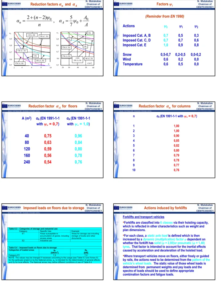
Reduction factors
α
n
and
α
A
2
4
6
8
10
0.5
0.6
0.7
0.8
0.9
1
n)
n
( )
2 n
( )
n)
n1)
n
( )
αn
2
4
6
8
10
0,8
0,7
0,6
0,5
0,9
Č
R (A, B)
UK
CEN, DE
FR (A, B)
n
Č
R (C, D)
FR (C, D)
20 30 40 50 60 0.5 0.6 0.7 0.8 0.9 1 A) N A( ) N1 A( ) ) A) A) 1 A( ) 2 A( ) A0,9
0,7
0,5
30
40
50
60
20
Č
R (A, B)
UK
FI
CEN
DE (A, B)
FR
DE (C, D)
A
[m
2]
α
AČ
R (C, D)
0,8
0,6
A
A
ψ
α
n
ψ
n
α
n
A
0
0
0
7
5
,
)
2
(
2
+
−
=
+
=
Factors
ψ
i
(Reminder from EN 1990)
Actions
ψ
0
ψ
1
ψ
2
Imposed Cat. A, B
0,7
0,5
0,3
Imposed Cat. C, D
0,7
0,7
0,6
Imposed Cat. E
1,0
0,9
0,8
Snow
0,5-0,7 0,2-0,5 0,0-0,2
Wind
0,6
0,2
0,0
Temperature
0,6
0,5
0,0
Reduction factor
α
A
for floors
A (m
2
)
α
A
(EN 1991-1-1
α
A
(EN 1991-1-1
with
ψ
o
= 0,7
)
with
ψ
o
= 1,0
)
40
0,75
0,96
80
0,63
0,84
120
0,59
0,80
160
0,56
0,78
240
0,54
0,76
Reduction factor
α
n
for columns
n
α
A
(EN 1991-1-1 with
ψ
o
= 0,7
)
1
1,00
2
1,00
3
0,90
4
0,85
5
0,82
6
0,80
7
0,79
8
0,78
9
0,77
10
0,76
Imposed loads on floors due to storage
Table 6.3 – Categories of storage and industrial use
Category Specific
Use
Example
E1
Areas susceptible to
accumulation of goods, including
access areas
Areas for storage use including
storage of books and other
documents
E2 Industrial
use
Table 6.4 – Imposed loads on floors due to storage
Categories of loaded areas
q
k[kN/m
2]
[kN]
Q
kCategory E1
7,5
7,0
NOTE The values may be changed if necessary according to the usage (see Table 6.3 and Annex A)
for the particular project or by the National annex. q
kis intended for the determination of general effects
and Q
kfor local effects. The National annex may define different conditions of use of Table 6.4.
Actions induced by forklifts
Forklifts and transport vehicles
•
Forklifts are classified into
6
classes
via their hoisting capacity,
which is reflected in other characteristics such as weight and
plan dimensions.
•
For each class, a static axle load
is defined which is then
increased by a dynamic (multiplication) factor
φ
dependent on
whether the forklift has
solid (
φ
= 2,00)or pneumatic (
φ
= 1,40)
tyres
. That factor is intended to account for the inertial effects
caused by acceleration and deceleration of the hoisted load.
•
Where transport vehicles move on floors, either freely or guided
by rails, the actions need to be determined from the
pattern of the
vehicle’s wheel loads.
The static value of those wheel loads is
determined from permanent weights and pay loads and the
spectra of loads should be used to define appropriate
combination factors and fatigue loads.
6
Actions induced by forklifts
Garages and vehicle traffic areas
NOTE 1 For category F q
k
may be selected within the range 1,5 to 2,5 kN/m
2
and Q
k
may be selected within the range 10 to 20 kN.
NOTE 2 For category G, Q
k
may be selected within the range 40 to 90 kN
NOTE 3 Where a range of values are given in Notes 1 & 2, the value may be set by
the National annex.
The recommended values are underlined.
Q
k
Q
k
q
k
5,0
Category F
Gross vehicle weight:
≤
30kN
Category G
30kN < gross vehicle weight
≤
160 kN
Q
k
[kN]
q
k
[kN/m
2
]
Categories of traffic areas
Table 6.8 – Imposed loads on garages and vehicle traffic areas
•
Category F (e.g. garages, parking areas, parking halls)
•
Category G (e.g. access routes, delivery zones, zones
accessible to fire engines)
Categorization of roofs
Categories of loaded area (of a roof) :
•
Category H
– Accessible for normal maintenance and
repair only
•
Category I
–
Accessible with occupancy according to
categories A to G
•
Category K
– Accessible for special services e.g.
helicopter landing areas
Imposed loads on roofs of Cat. H
•
The minimum values given in Table 6.10 do not take into
account uncontrolled accumulations of construction materials
that may occur during maintenance
•
Separate verifications to be performed for
Q
k
and
q
k
, acting
independently
NOTE 1 For category H q
k
may be selected within the range 0,0 to 1,0 kN/m2 and Q
k
may be
selected within the range 0,9 to 1,5 kN. Where a range is given the values may be set by the
National Annex. The recommended values are: q
k
= 0,4 kN/m
2
, Q
k
= 1,0kN
NOTE 2 q
k
may be varied by the National Annex dependent upon the roof slope
NOTE 3 q
k
may be assumed to act on an area A which may be set by the National Annex. The
recommended value for A is 10m
2
, within the range of zero to the whole area of the roof.
NOTE 4 See also 3.3.2 (1)
Q
k
q
k
Category H
Q
k
[kN]
q
k
[kN/m
2
]
Roof
Table 6.10 – Imposed loads on roofs of category H
Imposed loads on roofs of Cat. K
for helicopters
•
The dynamic factor
φ
to be applied to the take-off load
Q
k
to
take account of impact effects may be taken as
φ
= 1,40
0,2 x 0,2
0,3 x 0,3
Q
k
= 20 kN
Q
k
= 60 kN
Q
≤
20 kN
20 kN < Q
≤
60 kN
HC1
HC2
Dimension of the
loaded area (m x m)
Take-off load Q
k
Take-off load Q of
helicopter
Class of Helicopter
Table 6.11 – Imposed loads on roofs of category K for helicopters
Horizontal loads on partition walls
and parapets
Table 6.12 – Horizontal loads on partition walls and parapets
Loaded areas
q
k[kN/m]
Category A
Category B and C1
Categories C2 to C4 and D
Category C5
Category E
Category F
Category G
q
kq
kq
kq
kq
kSee Annex B
See Annex B
NOTE 1 For categories A,B and C1, q
kmay be selected within the range 0,2 to 1,0 (0,5)
NOTE 2 For categories C2 to C4 and D q
kmay be selected within the range 0,8 kN/m to -1,0 kN/m
NOTE 3 For category C5, q
kmay be selected within the range 3,0 kN/m to 5,0 kN/m
NOTE 4 For category E q
kmay be selected within the range 0,8 kN/m to 2,0 kN/m. For areas of
category E the horizontal loads depend on the occupancy. Therefore the value of q
kis defined as a
minimum value and should be checked for the specific occupancy.
NOTE 5 Where a range of values is given in Notes 1, 2, 3 and 4, the value may be set by the National
Annex. The recommended value is underlined.
NOTE 6 The National Annex may prescribe additional point loads Q
kand/or hard or soft body impact
specification for analytical or experimental verification.
7
Annex A (informative) : Nominal
densities and angles of repose
•
Table A.1 - Construction materials-concrete and mortar
•
Table A.2 - Construction materials-masonry
•
Table A.3 - Construction materials-wood
•
Table A.4 - Construction materials-metals
•
Table A.5 - Construction materials- other materials
•
Table A.6 - Bridge materials
•
Table A.7 - Stored materials - building and construction
•
Table A.8 - Stored products – agricultural
•
Table A.9 - Stored products - foodstuffs
•
Table A.10 - Stored products - liquids
•
Table A.11 - Stored products - solid fuels
•
Table A.12 - Stored products - industrial and general
Annex B (informative) : Vehicle
barriers and parapets for car parks
0
100
200
0
100
200
.
δ
c
=100 mm
δ
c
=200 mm
δ
c
=50 mm
δ
c
F
[kN]
The force in kN acting on 1,5 m of a barrier :
F
= 0,5
m v
2
/ (
δ
c
+
δ
b
) [kN]
the deformation of the
vehicle (mm)
the deformation of the
barrier (mm)
m
the gross mass of the
vehicle (kg)
v
the velocity of the
vehicle (m/s)
δ
b
δ
c
For vehicles < 2500 kg:
m =
1500 kg,
v
= 4,5 m/s,
δc
= 100 mm
Backgound Documents
and other supporting material
•
A more general reference to Background Documents (BD)
and related supporting material has been included and
presented in the Introduction to EN 1991. The BD on the
imposed loads on floors and roofs is already uploaded on
the relevant website.
•
Handbook 3
(Action Effects for Buildings) and Handbook 4
(Design of Bridges) of the Leonardo Da Vinci Pilot Project
for the Development of Skills Facilitating the Implementation
of Structural Eurocodes are considerd to be an appropriate
first approach for the deeper understanding of EN 1991.
•
Since a few years various books are being available (e.g. the
Thomas Telford collection of Guides)
Message for the near future
Please try on a national level to finalise and
issue the National Annex and upload the NDPs
in the ad-hoc data base of JRC Ispra
(if not already done so)
THANK YOU FOR
THANK YOU FOR
YOUR ATTENTION
EN 1991-1-3
P. Formichi
University of Pisa
Brussels, 18-20 February 2008 – Dissemination of information workshop 1 Background and Applications
EUROCODES
EN 1991 – Eurocode 1: Actions on structures
Part 1-3 General actions – Snow Loads
Paolo Formichi
Department of Structural Engineering
University of Pisa - Italy
Brussels, 18-20 February 2008 – Dissemination of information workshop 2
EUROCODES
Background and Applications
Scope of the presentation
Description of EN 1991-1-3 Eurocode 1: Part 1-3: Snow
Loads
Background research for snow maps for Europe,
Accidental (exceptional) loads, Shape Coefficients,
Combination Factors, etc.
Examples
Paolo Formichi, University of Pisa Italy
Brussels, 18-20 February 2008 – Dissemination of information workshop 3
EUROCODES
Background and Applications
Background research
Many clauses of EN 1991-1-3 are based on the results of a
research work, carried out between 1996 and 1999, under
a contract specific to this Eurocode, to DGIII/D3 of the
European Commission.
They were identified four main research items:
study of the European ground snow loads map
investigation and treatment of exceptional snow loads
study of conversion factors from ground to roof loads
definition of ULS and SLS combination factors for snow
loads.
Paolo Formichi, University of Pisa Italy
Brussels, 18-20 February 2008 – Dissemination of information workshop 4
EUROCODES
Background and Applications
Background research
The research results are contained in two final reports.
Paolo Formichi, University of Pisa Italy
http://www2.ing.unipi.it/dis/snowloads/
Brussels, 18-20 February 2008 – Dissemination of information workshop 5
EUROCODES
Background and Applications
EN 1991-1-3 Field of application
EN 1991-1-3 provides guidance for the determination
of the snow load to be used for the structural design
of buildings and civil engineering works for sites at
altitudes under 1500m.
In the case of altitudes above 1500m advice may be
found in the appropriate
National Annex
.
Paolo Formichi, University of Pisa Italy
Brussels, 18-20 February 2008 – Dissemination of information workshop 6
EUROCODES
Background and Applications
EN 1991-1-3 Field of application
EN 1991-1-3
does not give guidance
on the following
specialist aspects of snow loading:
“impact loads” due to snow sliding off or falling from a
higher roof;
additional wind loads resulting from changes in shape or
size of the roof profile due to presence of snow or to the
accretion of ice;
loads in areas where snow is present all the year;
loads due to ice;
lateral loading due to snow (e.g. lateral loads due to
dirfts);
snow loads on bridges
Brussels, 18-20 February 2008 – Dissemination of information workshop 7
EUROCODES
Background and Applications
Contents of EN 1991-1-3
Foreword
Section 1: General
Section 2: Classification of actions
Section 3: Design situations
Section 4: Snow load on the ground
Section 5: Snow load on roofs
Section 6: Local effects
ANNEX A: Design situations and load arrangements to be used
for different locations
ANNEX B: Snow load shape coefficients for exceptional snow
drifts
ANNEX C: European Ground Snow Load Maps
ANNEX D: Adjustment of the ground snow load according to
return period
ANNEX E: Bulk weight density of snow
Paolo Formichi, University of Pisa Italy
Brussels, 18-20 February 2008 – Dissemination of information workshop 8
EUROCODES
Background and Applications
Classification of actions
Actions due to snow are classified, in accordance with EN
1990, as:
Variable
:
action for which the variation in magnitude with
time is neither negligible nor monotonic
Fixed
:
action that has a fixed distribution and position
over the structure….
Static
:
action that does not cause significant acceleration
of the structure or structural members
Paolo Formichi, University of Pisa Italy
Brussels, 18-20 February 2008 – Dissemination of information workshop 9
EUROCODES
Background and Applications
Classification of actions
For particular conditions may be treated as
accidental actions:
action, usually of short
duration but of significant magnitude, that is
unlikely to occur on a given structure during the
design working life
Paolo Formichi, University of Pisa Italy
Exceptional
snow load on
the ground
Exceptional
snow drifts
Brussels, 18-20 February 2008 – Dissemination of information workshop 10
EUROCODES
Background and Applications
Definition of Exceptional snow load on the ground
Exceptional snow load on the ground
“load of the snow layer on the ground resulting from a
snow fall which has an exceptionally infrequent
likelihood of occurring”
Paolo Formichi, University of Pisa Italy
Brussels, 18-20 February 2008 – Dissemination of information workshop 11
EUROCODES
Background and Applications
Exceptional snow load on the ground
In some regions, particularly southern Europe, isolated very heavy snow
falls have been observed resulting in snow loads which are significantly
larger than those that normally occur. Including these snowfalls with the
more regular snow events for the lengths of records available may
significantly disturb the statistical processing of more regular snowfalls.
Paolo Formichi, University of Pisa Italy
Gumbel probability paper:
Pistoia (IT)
N° of recorded years = 51
N° of no snowy winters = 26
s
m
= Max. snow Load = 1.30 kN/m
2
50yrs load incl. Max Load = 1.00 kN/m
2
s
k
= 50yrs load excluded Max Load =
0.79 kN/m
2
k = s
m
/s
k
= 1,65
0.79
1.00
Brussels, 18-20 February 2008 – Dissemination of information workshop 12
EUROCODES
Background and Applications
Exceptional snow load on the ground
The
National Annex
should specify the geographical locations
where exceptional ground snow loads are likely to occur.
When the maximum ground snow load is to be considered as
exceptional?
“If the ratio of the largest load value to the characteristic
load determined without the inclusion of that value is
greater than 1.5 then the largest value should be
treated as an exceptional value”
According to this definition over
2600
weather stations from 18 CEN
countries (1997), in
159
they were registered exceptional ground
snow loads.
Paolo Formichi, University of Pisa Italy