Comparative Study of CAD Software, Web3D Technologies and
Existing Solutions to Support Distance-Learning Students of
Engineering Profile
Zona Kostic1, Dusko Radakovic2, Dragan Cvetkovic1, Srdjan Trajkovic2, Aleksandar Jevremovic1 1 Singidunum University
Belgrade, 11000, Serbia
2 College of Professional Studies – Belgrade Polytechnics Belgrade, 11000, Serbia
Abstract
Interactive simulations, virtual environments and 3D interfaces significantly contribute to the process of learning through collab-oration and interaction with distant participants, and through simulation of real environments and real life situations. Depend-ing on the needs and case studies, different technologies, soft-ware packages and their combinations are used. In this paper, we present a comparative study based on the use of different CAD software in conjunction with Web3D technologies for teaching students at the Department of Engineering Management. With respect to the specificity of the profile of students undergoing training, the selection of CAD packages is reduced to the five most commonly used in this field: SolidWorks, Inventor, CATIA, Pro/ENGINEER and AutoCAD. During research, we found that Inventor and AutoCAD do not export VRML/X3D file types; hence, this paper provides only the basic functions of Inventor without integration of Web3D technologies. Combining with AutoCAD is described due to the existence of a number of plug-ins, as well as exporters and working groups working on Auto-CAD-X3D development. The main criteria for evaluating and ranking CAD packages used here are learning curve, export and import from CAD to X3D and vice versa, file types and sizes, types of nodes and material properties. We also review the tech-nology used to display 3D content on the Internet, and the rea-sons why we decided to use Web3D technologies in combination with these CAD packages. This paper presents specific conclu-sions, the advantages and disadvantages of software and technol-ogy, as well as predictions regarding further development of existing platforms and environments.
Keywords: CAD (AutoCAD, CATIA, Pro/ENGINEER, Inventor, SolidWorks) + X3D virtual engineering environments, CAD + X3D virtual classroom, CAD + X3D + virtual design/assembly
1. Introduction
CAD (Computer Aided Design) packages have been used since the early ‘70’s [1] but the size of the 3D model, compatibility issues in cross-platform environments, and
limited flow over Internet still present a problem in terms of their exchange and sharing. Development of standards for exchange of 3D objects over Internet (details of these standards are discussed in Chapter 2 Background and Mo-tivation) has helped in developing specific applications for designing, planning, education, etc. Although new genera-tions of students have more advanced IT knowledge com-pared to their older colleagues, they still lack of attention and the ordinary multimedia makes it difficult to use tradi-tional methods.
All this abovementioned is particularly evident in situations where practical work in studying is of crucial importance. For students of engineering management, practical work provides an understanding of basic concepts such as data analysis, problem solving and scientific interpretation [2]. For this reason, attention is increasingly drawn towards the use of virtual classrooms and labs that surpass the limita-tions of existing distance learning systems, enabling virtu-alization of real-life exercises or even overcome the limita-tions of real environments [3]. As everything is being trans-ferred from real to virtual environments (VEs), there arise new terms and fields like virtual design, virtual engineering, virtual assembly, etc.
Tool support has a significant role in the successful im-plementation in designing products. Possible integration of its functions, such as assembly techniques in VEs, creates high quality virtual laboratories. Such laboratories can be used to overcome excessively high expenses (assembly costs) in training and not just for practical exercises in dis-tant education. There is a wide range of programs for 3D modeling, from simple home-brew systems, to high-end professional packages. Regarding technologies for display-ing 3D content on the Internet, most of the existdisplay-ing solu-tions do not meet all funcsolu-tions of Collaborative Virtual Environment (CVE) systems such as audio or networking [4]. A comparative study later in this paper shows in detail all the advantages and disadvantages.
This paper is organized into six sections, including this introductory section. In Section 2, the background and motivation are described. Section 3 provides basis for comparison. Section 4 represents review of CAD software. Existing platforms, as well as solutions that include X3D in combination with CAD software are presented in Section 5. Finally, Section 6 presents conclusions and predictions on future developments.
2. Background and Motivation
Prior to working in a virtual environment, students were introduced with the basics of engineering, basic rules of design and technical drawing, as well as creation and fol-low-up of technical documentation. Based on the above, students were able to read technical documentation related to a given element (subassembly) and model given parts in a CAD program of their choice. Afterwards they begin product assembly with defined constraints in collaboration with other participants in the virtual environment. The de-signed assembly will indicate whether it is valid in terms of geometry and kinematics, and an eventual mismatch will be shown as an accompanying text, from which they can conclude what is wrong and how it can be repaired. Most CAD programs possess modules for assembling and collaboration with other departments in context of monitor-ing, development and product life cycle [5]. Many solu-tions related to distributed and collaborative virtual proto-typing, interactive design and manufacturing simulation of mechanical products are presented in [6]. Most of the listed solutions do not have the possibility of collaboration in virtual environment and, hence, work together using various software packages. In our work, we focused on technology, standards and platforms as well as potential solutions for creating these types of VEs, just to provide shared work within the same virtual environment using various CAD software packages.
In [7], the author pointed out that “the software engineer-ing environment supports the project team, the process, and the product. But if the environment is flawed, it can be the source of significant risk.” To reuse the models created in different CAD packages the environment itself would have to possess a higher degree of stability. In this paper [8], is presented a survey of some popular 3D graphics file types, programming tool libraries, authoring tools, and format conversion tools used for creating VEs. There are certain difficulties in sharing 3D models, because they are either too complex or heavyweight to be shared for distrib-uted collaboration. For that reason, lightweight formats exist and an excellent survey of technologies that actually enable the presentation of 3D data in the Internet is pre-sented in [9].
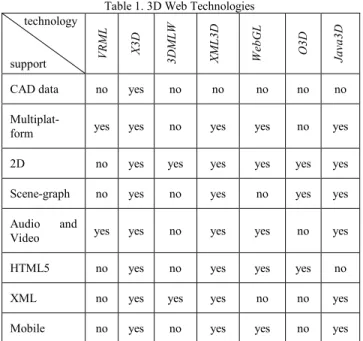
Table 1. 3D Web Technologies technology support VRM L X3 D 3DM LW XM L3 D W eb GL O3 D Ja va 3D
CAD data no yes no no no no no
Multiplat-form yes yes no yes yes no yes
2D no yes yes yes yes yes yes
Scene-graph no yes no yes no yes yes Audio and
Video yes yes no yes yes no yes
HTML5 no yes no yes yes yes no
XML no yes yes yes no no yes
Mobile no yes no yes yes no yes The most commonly used 3D Web technologies are X3D (eXtensible 3D) and WebGL (Web-based Graphics Li-brary), both designed for creation of interactive Web-based and broadcast-based 3D content, suitable to integrate with multimedia. However, there is a significant difference be-tween them and their use largely depends on the specific need. For example, WebGL as much progressive brings hardware-accelerated 3D graphics. It works without in-stalling additional software, but only within compatible Web browsers. Regardless of the fact that X3D works at much lower level and needs installation of an appropriate plug-in, it enables displaying within any Web browser, and as scene-graph system and with XML encoding, it’s a much better choice for beginning students.
When speaking of CVE creation, an excellent review of API’s, Frameworks and Platforms is given in [4]. In the same paper, it is concluded that technology that is most conductive to build and deploy CVEs is Xj3D [10]. Be-sides Xj3D API’s, also are listed platforms Open Wonder-land [11] and Croquet [12]. These platforms eliminate the need for end-user expertise and additional computing pow-er. The Web3D Consortium, besides the VRML and X3D standards, maintains the Xj3D and it is a mature implemen-tation of the X3D standard, offering a graphics rendering mechanism, audio and network components. It includes the use of a scene graph to manage VR information, support of XML to encode VR scenes, compatibility with VRML/X3D and the ability to operate as a Java applet or stand-alone application.
From the previous, it is concluded that different technolo-gies have different purposes, and, according to our needs, Web3D technologies (X3D and Xj3D with support for audio and networking) were selected for creation of CVE
as a general format for creating assemblies. This choice was also contributed by our experience with students who were creating environments (mainly students from the De-partment for Computer Graphics). Very fast and very effi-ciently, students came to solution using X3D technologies, because the scene-graph structure was most suitable for students of this profile. In addition, Xj3D support multiple CAD filter capabilities for geometry simplifications and profile reduction, and X3D provides support for CAD-to-X3D conversion with CAD Assembly Structure.
3. Basis of comparison
This section provides an overview of CAD software. Five packages were chosen by specific student profile and pres-ence in the market. In addition, packages can be estimated in terms of creating specific parts that will be used in X3D virtual environments as universal environments for creat-ing assemblies. The selected packages are SolidWorks [13], Autodesk Inventor [14], CATIA [15], Pro/ENGINEER (PTC Creo, Pro/E) [16], and Autodesk AutoCAD [17]. These are the most widely used versions in 2012. Although, at the time of writing this paper, Inventor was already re-leased with version 2013, and it turned out that using this release requires considerable resources, which would fur-ther burden the process. The comparison focuses on fea-tures that easily create accurate models of arbitrary objects. In this case, only a low level of detail is necessary because ultimately the objects will be used in a real-time environ-ment. In addition, Inventor does not have export capabili-ties for VRML/X3D file types; hence, the rest of this paper presents only basic functions (Inventor) without integration with Web3D technologies.
During the assessment of individual parts, such as learning curve rate, different groups of students participated from different faculties. Students from the Faculty of Engineer-ing Management use SolidWorks, AutoCAD and CATIA are used at the Faculty of Mechanical Engineering, and Pro/E is used in the Technical School “Novi Beograd”, Technical Faculty of Novi Sad, and the College for Profes-sional Studies “Belgrade Polytechnics”. Other findings were derived on individual basis of each of the authors’ excessive experience working with a CAD application. The comparison incorporates several criteria:
• Learning curve rate / Ease of use
Ease-of-use is an important factor in using CAD systems. It also impacts long term productivity. This category compares how easy it is to see the object and manipulate the view panes. Rudimentary questions were like: How much time is it needed to master 2D drawing, 3D model-ing, and assemblies? During assessment significant was the understanding of basic concepts in X3D technologies, as well.
•Export capabilities towards VRML or X3D file types; availability of plug-ins as a substitute for direct ex-port
Output to VRML or X3D is a prerequisite for considera-tion in this work. All objects will have to put into VRML or X3D (if the program only exports to VRML, there might be a possibility it has an X3D plugin-in) so they can be translated into a virtual environment. This catego-ry compares the program’s flexibility and support for one of the two Web3D technologies.
•Method of export (node type)
The X3D specification [18] defines a rich set of built-in nodes, grouped in 24 components and 5 profiles. A com-ponent is typically a set of X3D nodes, which can be or-ganized into levels, defined by a set of nodes. A profile consists of a collection of components and levels of each component, whereby a minimum support criterion is de-fined for all nodes of the component. However, there are differences in displaying the same objects. (For example, a box is displayed as a defined Box node, but also as an IndexedFaceSet node. Furthermore, every node has dif-ferent attributes that influence the application develop-ment.)
•Texture map or material properties
This criterion is mainly related to the previous one and depends on the method how the object is exported from CAD software. Appearance affects the associated geome-try, containing the visual surface properties that interact with lights (Material, TwoSidedMaterial, LineProperties, and FillProperties), or texture nodes wrap images onto geometry (ImageTexture, MovieTexture, PixelTexture, MultiTexture, TextureTransform, TextureCoordinate, and TextureCoordinateGenerator).
4. Review of CAD software
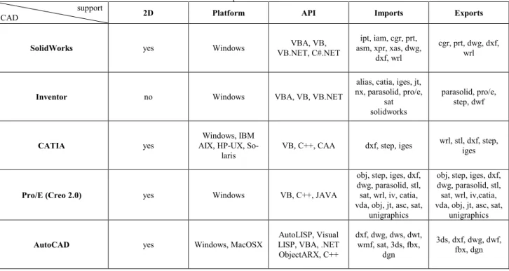
By now, it should be obvious that there is no one best 3D modeling program for all model-building applications. For some tasks, there are programs that are more suitable among other, and each of programs we evaluated handled different sets of tasks. In fact, inertia is actually the most compelling factor in choosing modeling programs. The remainder of this paper presents a detailed analysis for five selected CAD packages. Table 2 presents the basic features of the proposed CAD packages.
Table 2. Comparison of CAD software support
CAD 2D Platform API Imports Exports
SolidWorks yes Windows VB.NET, C#.NET VBA, VB, asm, xpr, xas, dwg, ipt, iam, cgr, prt, dxf, wrl
cgr, prt, dwg, dxf, wrl
Inventor no Windows VBA, VB, VB.NET
alias, catia, iges, jt, nx, parasolid, pro/e,
sat solidworks
parasolid, pro/e, step, dwf
CATIA yes AIX, HP-UX, So-Windows, IBM
laris VB, C++, CAA dxf, step, iges
wrl, stl, dxf, step, iges
Pro/E (Creo 2.0) yes Windows VB, C++, JAVA
obj, step, iges, dxf, dwg, parasolid, stl, sat, wrl, iv, catia, vda, obj, jt, asc, sat,
unigraphics
obj, step, iges, dxf, dwg, parasolid, stl, sat, wrl, iv,catia, vda, obj, jt, asc, sat,
unigraphics AutoCAD yes Windows, MacOSX LISP, VBA, .NET AutoLISP, Visual
ObjectARX, C++ dxf, dwg, dws, dwt, wmf, sat, 3ds, fbx, dgn 3ds, dxf, dwg, dwf, fbx, dgn
4.1 SolidWorks
Learning curve rate / Ease of use
Students ranked SolidWorks as easy to use, which was consistent for adopting from both 2D and 3D CAD. Re-spondents also reported a higher level of satisfaction. Greater ease-of-use and a higher level of satisfaction are illustrative of a more enabling software design tool. Stu-dents were also able to create and manage larger and more complicated projects with more confidence in the same amount of time needed for smaller project done in their previous systems. They were able to design products as easily as they were imagined, whereas before designs had to be compromised because of the CAD system. They were also able to produce useful drawings within two weeks. All the changes are immediately reflected in assemblies and parts.
Export capabilities towards VRML or X3D file types; availability of plug-ins as a substitute for direct export
SolidWorks exports only VRML 1.0, which is in this com-parison a significant disadvantage. Besides, SolidWorks does not possess a plug-in for X3D. In this case, the con-version is realized by exporting into another file format that can be imported into the X3D environment.
Method of export (node type)
Parts from SolidWorks are exported into VRML as In-dexFaceSet nodes, even when they are as simple as cubes,
cylinders, sphere an alike, for which there are correspond-ing nodes in the X3D specification.
Texture map or material properties
Material is exported using the Collada exporter, but it is not possible with VRML 1.0. Both of these export attrib-utes ambientColor, diffuseColor, emissiveColor, specular-Color, shininess, and transparency.
4.2 Inventor
During the study, it came to our knowledge that Inventor cannot export VRML/X3D file types. Accordingly, pre-sented in this paper are only the basic functions without integration with Web3D technologies.
Regarding the environment, Inventor has a very simple (friendly) interface and is well organized with a simple help system. As such, usually 30 hours is sufficient to mas-ter the program at an inmas-termediate level, and around 60 hours for advanced techniques. The program is used by small design/manufacturing companies specialized in pro-duction of sheet metal products, piping and wiring of elec-trical/electronic equipment. Using add-on applications can enable Inventor to export to VRML, but they have proved to be insufficient as a solution. As for exporting to STEP format, there is no problem since Inventor release 2010 (in the remainder of this paper it will be explained in more detail why this format is so important).
4.3 CATIA
Learning curve rate / Ease of use
Students ranked CATIA V5R21 as a package not too com-plicated to work in, which is consistent to the other pro-grams. Working in CATIA is very similar to working in Pro/E. The relative ease of use, as well as certain satisfac-tion at work is caused by use of software tools within the program. Students were also able to create complex pro-jects, which included modeling and generating subassem-blies and assemsubassem-blies. They were able to design products as imagined, although the use of this package enabled them to create a compromised solution in terms of many parame-ters. Students have also shown capability to do serious tasks in CATIA just after two weeks of training. These tasks include preparation of technical documentation be-sides modeling individual parts and complex assemblies. In addition, there is interconnectivity between CATIA and SolidWorks, since they are products of the same vendor.
Export capabilities towards VRML or X3D file types; availability of plug-ins as a substitute for direct export
Files from CATIA can be exported by the CATIA VRML exporting API, and then converted into X3D by the VRML2X3D converter [19].
Method of export (node type)
Files are exported as VRML with IndexedFaceSet nodes, and like that are converted from VRML into X3D.
Texture map or material properties
Materials from CATIA is exported into VRML as ambi-entColor, diffuseColor, emissiveColor, specularColor, shininess, and transparency.
4.4 Pro/ENGINEER
Learning curve rate / Ease of use
The creation of the 3D models with Pro/E is based on working with so-called “features”, which describe the models geometry and additional properties of the part or assembly. Using the main volume features, the material can be added (protrusion feature) or removed (cat feature). Very basic modeling and assembly creation is very simple to do in Pro/E. Many of the people that learn it in college learn very little about what Pro/E can really do. An appli-cation that truly has a vast array of functionality takes time to learn. There is no way around it. One can only learn so much on their own and the reality is there is a lot of trial an error involved. Agreed there is still a little trial and error involved after formal training, but one at least has a solid foundation of what functionality exists.
Export capabilities towards VRML or X3D file types; availability of plug-ins as a substitute for direct export
Creo 2.0 exports VRML format in version of VRML 2.0 utf-8. There is no plug-ins available for X3D export from PTC Creo 2.0.
Method of export (node type)
Parts are exported into VRML as IndexedFaceSet nodes.
Texture map or material properties
Materials are not exported, but attributes like ambientCol-or, diffuseColambientCol-or, emissiveColambientCol-or, specularColambientCol-or, shininess, and transparency are.
4.5 AutoCAD
Learning curve rate / Ease of use
Students of the Faculty of Mechanical Engineering had training in AutoCAD. Unlike SolidWorks and Pro/E, Au-toCAD is significantly more complex and it is necessary 40 hours to master 2D drawing, and 30 hours to complete 3D drawing. This implies that 50 hours of training were necessary; having in mind that it is not possible to start 3D modeling without training in 2D. Amongst trained students, we had students with previous experience in using Auto-CAD. Interesting about this was that students without any experience more swiftly mastered the program compared to students having previous hands-on experience. As they themselves stated, the reason for this is that the new ver-sions had a more intuitive GUI and quite reminiscent of Microsoft Office.
Export capabilities towards VRML or X3D file types; availability of plug-ins as a substitute for direct export
AutoCAD cannot export into VRML and neither into X3D. Fortunately, this package works with a large group of ex-porters and translators. A special task group is working on integration of AutoCAD with X3D.
5. Review of existing environments
(VE and VLE + VRML/X3D)
The criterion for review is based on non-commercial solu-tions that can import models (part or assembly) from a specific program. On the other hand, there is a vast majori-ty of commercial solutions, but they not considered in this paper.
The three case studies of interactive Web-based environ-ments for online learning were developed using the X3D standard [20]. These solutions introduce Web3D-based laboratories, which address the challenges among the engi-neering major students. Solutions are part of engiengi-neering course aimed to introduce students to the fundamentals in engineering theory as well as practice. The interesting so-lution that utilizes X3D for creating virtual laboratory, presented in [21], describes a great course for engineering students using virtual assembly techniques. This solution only lacks in collaboration, text or video chat. The solution [22] combines as many characteristics of the X3D virtual lab and assembly as possible, which was an excellent start-ing point for our research. Followstart-ing is an excellent
inter-face [23] with many functions enabled, with only limited collaboration on individual work during the design. Most of the mentioned systems combine SolidWorks with X3D technology.
Virtual Manufacturing system for enterprises with limited resources is presented in [24]. The system preforms col-laborative tasks, including product design, manufacturing and resources. The manufacturing lab uses X3D in combi-nation with Pro/E, AutoCAD, and similar CAD software, as well as a knowledge-based expert system for product assessments. Paper [25] describes a system combined of CATIA and VRML, which enables participants to share their design capabilities in order to complete a common product design. The system in its simulation part enables user to carry on analysis based on help of CAE software. It is important to mention two virtual assembly systems, [26] and [27], created using X3D without detail of any specific CAD software. They allow users to manage prod-ucts information in 3D environment, automatically save information in database. Both X3D virtual assembly envi-ronments are without capabilities stated as priority at the beginning of this paper.
6. Conclusions and future developments
In this paper, we proposed a possible combination of CAD software and X3D technology aimed for creating virtual laboratory for engineering students. In this section, we point out general conclusions regarding the described technologies and platforms, as well as predictions con-cerned with the current working groups and support solu-tions to create a universal format for the exchange.Significant exporters and project initiatives for creation of universal format to exchange CAD files are a mid-step in the X3D technology. A substantial exporter that applies to all CAD program mentioned in this paper is Okino. It has the support for STEP to X3D functionality. This export converter, as a proprietary package is beyond scope of this approach, but another web application – SPRI (a lot less capabilities, but a non-commercial software) [28] – is an application which also offers translation of STEP into X3D. Translating STEP into X3D is very suitable for data ex-change. Since all CAD applications considered in this pa-per offer export into STEP format, this translation of STEP to X3D suggests a path to generate X3D content using modeling capabilities of these applications. Another step forward is the effort from CAD3D Working Group, which have defined a file format and data transfer process. The format named CAD Distillation Format (CDF) enables translation of CAD data to an open format for publishing. The process includes an open framework pipeline that in-corporates tools for devastation of surfaces to structures that are more common in the non-CAD environments. The
CAD Distillation Filter is a process that provides filtering to reduce and refine a single X3D model [29].
When addressing the combination CAD – X3D, most solu-tions come as combination of SolidWorks and X3D. This is because SolidWorks exports models with the least num-ber of polygons, in addition to the fact that it is the easiest to master amongst the mentioned packages. Unfortunately, SolidWorks has a considerable drawback – there is no di-rect export into X3D, and in order to do so it has to be done via VRML or Collada exporter. CATIA has the best communication with X3D. A lot of effort is invested into their integration (CAD3D Work Group). CATIA has the option to import complete assemblies into X3D (assem-blies from other programs are exported into VRML/X3D as complete models). In this case, it is obvious that the disadvantage of AutoCAD not being able to export into STEP seams negligible. As for Pro/E, although there is a basis for integration of the X3D, no efforts are made in this direction. Probably because Pro/E relies on the U3D for-mat, as well as on native formats of other CAD packages. The future of creating a universal format could lay within the CAD3D Work Group, with their general objectives to be: preferring parametric representations for brevity and precision; enabling option to save CAD product structure in the use of named X3D CAD product structure nodes; defining, implementation, demonstration and distribution of the workflow for converting CAD models to X3D. In the present (while still using translators and converters), when creating a model that will later on be part of a VE or CVE, we should bear in mind the following:
• Formats that don’t keep names and hierarchy are diffi-cult to handle because the identification of objects is not clear and the assemblies’ structure is lost.
• For keeping the realistic appearance of a CAD model it is necessary to use data formats that can encode materi-al information.
• For increasing efficiency and accelerating performance, the use of level of detail in objects is very profitable. In addition to integrating as much CAD packages with Web3D technologies, our future work will be directed to exporting drawing files from the virtual assembly lab and link these with all previously created parts (associative feature in all CAD programs). Mentioned functions could be extended to haptic-enabled tools or CAVE system for sharing, learning, and testing.
References
[1] F. Tian, X. Tian, J. Geng, Z. Li, Z. Zhang, “A Hybrid Interac-tive Feature Recognition Method Based on Lightweight Model”, Proceedings of the 2010 International Conference on Measuring Technology and Mechatronics Automation, 2010.
[2] B. Wu, G. Cheng, “Moodle - The Fingertip Art for Carrying out Distance Education”, Proceedings of the 2009 First
In-ternational Workshop on Education Technology and Com-puter Science, 2009.
[3] A. Choi, D. Chan, A. Yuen, “Application of Virtual Assem-bly Tools for Improving Product Design”, Department of Manufacturing Engineering, The Hong Kong Polytechnic University, 2002.
[4] T. Wright, G. Madey, “A Survey of Technologies for Build-ing Collaborative Virtual Environments”, International Jour-nal of Virtual Reality, 2009.
[5] Modern CAD/CAE/CAM Tools and Their Applications http://www.engr.uvic.ca/~mech410/old/2_Lecture_Notes/1_ CADCAECAM_Review.pdf (accessed May 29, 2012). [6] M. Kerttula, “A Framework for the Development of Personal
Electronic Products”, VTT Technical Research Centre of Finland, 2006.
[7] R. Pressman, “Software Engineering: A Practitioner's Ap-proach”, Fourth ed., pp. 139-140, McGraw-Hill, 1997. [8] J.Chen, Y. Yang, “3D graphics formats and conversions”,
Computing in Science and Engineering, 2000.
[9] B. Turonova, „3D Web Technologies And Their Usability for The Project 3D Mobile Internet“, 2009.
[10] Xj3D http://www.xj3d.org/ (accessed May 29, 2012). [11] Open Wonderland http://openwonderland.org/ (accessed
May 29, 2012).
[12] Open Croquet SDK http://www.opencroquet.org/ (accessed May 29, 2012).
[13] Solidworks - http://www.solidworks.com/ (accessed May 29, 2012).
[14] Inventor - http://usa.autodesk.com/autodesk-inventor/ (ac-cessed May 29, 2012).
[15] CATIA - http://www.3ds.com/products/catia (accessed May 29, 2012).
[16] Pro/E - http://www.ptc.com/product/creo/parametric (ac-cessed May 29, 2012).
[17] AutoCAD - http://usa.autodesk.com/autocad/ (accessed May 29, 2012).
[18] X3D specification -
http://www.web3d.org/x3d/specifications/ (accessed May 29, 2012).
[19] CAD2X3D Conversion
http://www.web3d2011.org/p/Workshop_CAD_Lee.pdf (ac-cessed May 29, 2012).
[20] F. Hamza-Lup, P. Goeser, W. Johnson, T. Thompson, E. Railean, D. Popovici, G. Hamza-Lup, "Interactive 3D Web-Based Environments for Online Learning: Case Studies, Technologies and Challenges," International Conference on Mobile, Hybrid, and On-line Learning, 2009.
[21] P. Goeser, W. Johnson, F. Hamza-Lup, D. Schaefer, “VIEW: A Virtual Interactive Web-based Learning Envi-ronment for Engineering”, IEEE Advances in Engineering Education Journal, Special Issue on Research on e-Learning in Engineering Education, 2011.
[22] P. Goeser, W. Johnson, F. Hamza-Lup, I. Sopin, M. Brund-age, M. Carroll, “ A VIEW on Mechanical Dissection for Freshmen Engineering”, ASEESE Section Annual Confer-ence, 2010.
[23] L. Haiqing, Y. Guofu, F. Jie, “Research on the Collaborative Virtual Products Development Based on Web and X3D”, Proceedings of the 16th International Conference on Artifi-cial Reality and Telexistence, 2006.
[24] L. Jin, Z. Wen, I. Oraifige, “Distributed VR for Collabora-tive Design and Manufacturing”, Proceedings of the 11th In-ternational Conference Information Visualization, 2007. [25] S. Ma, Z. Gao, “A Solution to Integrate CAD/CAE System
and VR for Complex Product Design Processes”, Proceed-ings of the 2009 Second International Conference on Infor-mation and Computing Science, 2009.
[26] L. Haiqing, Y. Guofu, F. Jie, “Research on the Collaborative Virtual Products Development Based on Web and X3D”, Proceedings of the 16th International Conference on Artifi-cial Reality and Telexistence, 2006.
[27] C. Cheng, X. Cai, R. Jiang, “Object Behavior Specification and Simulation in Virtual Assembly”, Workshop on Digital Media and Digital Content Management (DMDCM), 2011. [28] CAD/CAM models delivered as X3D content
http://www.kshell.com/pages/x3d_cad/index.html (accessed May 29, 2012).
[29] CAD Distillation Format -
http://www.web3d.org/x3d/workgroups/cad/ (accessed May 29, 2012).
Zona Kostic Graduated in 2006 (computer graphics field), Master of science in 2008. Participation in projects in the field of computer graphics and animation. Teaching assistant at Singidunum Uni-versity, Belgrade, Serbia. Research interests: computer graphics and animation, virtual environments, Web-based game develope-ment, Web-based education.
Dusko Radakovic Graduated in 1990 at the Faculty of Mechani-cal Engineering, Belgrade University, Dept. of Aerospace Engi-neering. Masters Degree attained at the Faculty of Mechanical Engineering, Belgrade University and at the Belford University. Doctoral degree acquired at the Belford University. Relevant work experience in Teleoptik AD, Serbia, and at Methode Electronics Malta Ltd., Malta, as CAD expert and senior product design engi-neer. Since 2002 working as an expert associate at the College of Professional Studies - Belgrade Polytechnics. Research interests: virtual prototyping, computer graphics, web-based education, artificial intelligence, micro factories, micro machines.
Dragan Cvetkovic Graduated in 1988 at the Faculty of Mechani-cal Engineering, Belgrade University, Dept. of Aerospace Engi-neering. Magister of Science acquired at the same department in 1992. In 1997 attained doctoral degree. Participated in numerous projects within the Institute of Aviation, Faculty of Mechanical Engineering, Belgrade University. Since 2007 teaching at Sin-gidunum University, Belgrade, as assistant professor. As of Au-gust 1st, 2011, acting as Dean of the Faculty for Management, Studies of Engineering Management.
Srdjan Trajkovic Graduated at the Faculty of Mechanical neering, Belgrade University, in 1989, Dept. for Production Engi-neering. Acquired Masters Degree in 2009 at the Faculty for In-formatics and Computer Science, Singidunum University, Bel-grade. Since 1993 working as an expert associate at the College for Professional Studies – Belgrade Polytechnics.
Aleksandar Jevremovic Graduated in 2005, Magister of science in 2007, PhD in 2011 (network security field). Assistant professor at Singidunum University, Belgrade, Serbia. Research interests: computer networks, artificial intelligence, network security, com-puter aided learning.