Rotor Loading Test with Wireless Transmitting
MA YapingˈLIU Ming, HE Jing, GU Shipeng, LIU Peng
Chinese Flight Test EstablishmentˈXi’an 710089ˈChina
E-mail address:[email protected]
Abstract: Helicopter rotor loading and strength flight test is the studying stress loading spectrum of airplane test in actual atmosphere. In the rotor loading test the test devices in the rotor should be strong anti-interference, small size, light weight because rotor high spin speed produces centrifugal force loading with high temperature gas and hot noise. Traditional rotor loading test solution of helicopter cannot meet present requirement due difficult balance between signal transmission reliability and test data real-time acquisition. This article propose a method for multi-channel, wide bandwidth and accurate synchronization rotor loading test with modular, redundancy and high integration design to modulate, transmit and demodulate the dynamic loading data.
Key words: Rotor system; Load; Wireless Transmitting; Time synchronization 1. Introduction
Helicopters are widely used in military and civilian fields because of the characteristics of vertical take-off and landing, hovering, and slow speed which are not available in fixed wing aircraft. As the key component of the helicopter, the rotor system not only provides lift and forward force for the helicopter, but also provides the longitudinal and lateral steering torque of the helicopter in order to achieve the helicopter's course operation. The aerodynamic characteristics of rotor system determine helicopter performance, quality and reliability, which are the main sources of vibration and noise of helicopters. The stress load spectrum of rotor system determines the safe service life of helicopter. Therefore, the load test of the rotor system in the helicopter flight test is the key subject. To obtain the rotor load test data
for the helicopter fatigue and life it is a necessary for the helicopter load and strength flight test. Improper handling of rotor system components will directly affect the aircraft control system and endanger flight safety. In the process of high-speed rotation, the rotor system produces very large centrifugal overload and is mixed with high temperature air, so the testing equipment installed on the rotor should be reliable, accurate and small. It is crucial not only to obtain real reliable, high precision flight data, but also to ensure flight safety.
This paper mainly describes wireless transmission technology to achieve data acquisition and transmission of rotating components in the flight test of rotor system. 2. Characteristics and key technologies
of rotor load test technology
composed of main hub, tilt plate, damper, elastic parts and blades and other components to achieve the helicopter's maneuvering flight. Rotor system is one of the most complex structures of helicopters, and many mechanical components are spin components. Rotating parts inevitably cause vibration in practical work. Excessive vibration will cause damage to helicopter structure. Therefore, the strength load test of the relevant components of the rotor system is a key subject in the helicopter flight test. At present, rotor system load flight test requires at least 80 test parameters, and the sampling rate is at least 1K Sa/s.
Rotor load test is a key test subject in helicopter flight test. The rotor will produce very large centrifugal overload and high temperature airflow in the process of high speed rotation, so the testing equipment installed on the rotor system needs to be reliable, accurate and small. It is crucial not only to obtain true, reliable and high precision flight data, but also to ensure flight safety. The contact measurement in early rotor system load test is to supply load strain power and send test signal through brush collector ring. The working principle of the brush collector ring is signal transmitting through the brush installed between the moving and static parts, it will produce a lot of noise in the process of high speed rotation of the rotor, which can easily lead to the distortion of the load strain signal waveform, and its anti-interference performance is poor. Later, to avoid distortion of the signal transmission the rotor load test is mainly to integrate acquisition and recording system
by installing the measuring equipment on the rotating parts, and then output signal of the load sensor is tested and recorded directly, without the conversion and transmission of any intermediate link. However, the scheme can not carry on the telemetry transmission to monitor the real-time load data, and it is difficult to synchronize the time for the airborne testing systems to guarantee the time correlation. Due to the limitation of the technology, the load parameters can not meet flight test requirement for the quantity and the sampling rate. Therefore, the key technologies of the rotor system load testing are non-contact wireless signal transmission technology, rotating component power supply technology and nonstandard component customization technology. Non-contact wireless signal transmission is an innovation of contact measurement method, which overcomes a series of problems such as noise interference from the traditional contact test, and the technology has high maturity. It is also the inevitable trend of the measurement technology development of the rotor system in the future. The method uses signal wireless transmission or photoelectric technology to overcome the acquisition and transmission of strain signals, and the wireless connection of the test data between the dynamic and static parts of the rotor system is realized in the process of rotation of the rotor system. The technology of non-contact wireless signal transmission is to modulate the collected data through frequency and send it to a telemetry receiver at a specific frequency. The telemetry receiver sends the
demodulated strain signals to the airborne data acquisition system in a specific form. This can effectively overcome the data transmission problem of rotating parts.
At present, the more advanced technology is to install acquisition module in rotating parts installation, which has amplifying, acquisition, modulation and transmitting for the test signals. Through the installing receiving device in the cabin, the real-time data acquisition and recording are realized, with the Ethernet data extraction technology inserted into the airborne network test system of the helicopter flight test status can be real-time displayed to both pilot and the ground safety monitoring station.
The power supply technology of rotating parts and the nonstandard parts customization technology is the design for dual redundancy power supply for the rotor load testing system and the design of the testing mechanism for the high centrifugal overload environment basing on the mechanical structure characteristics of the rotating parts.
3. Design of load test system based on wireless transmission
3.1 Design principles
According to the requirements of flight test, the characteristics of the test signal type, range and frequency response of the measured signal, the reliability, advanced and extensibility of the rotating part load testing system are fully considered, and a test scheme for rotating parts to meet the requirements of the flight test environment is designed.
The main functions of the rotor load test
system used for flight test are as follows: 1) The system has the ability to test dynamic strain.
2) Considering the complexity and safety monitoring of rotor installation, the system has the capability of wireless signal transmission.
3) Wireless transmission channels are independent of each other and have fast migration capability.
4) Measurement accuracy of analog sinals is better than 1%.
5) The system has precise time synchronization (better than 1ms).
6) With IRIG-B time signal input function, it ensures time consistency with the airborne networked test system.
7) The number of signal acquisition channels is greater than 80, and the sampling rate is more than 1KSa/s.
8) Double redundant power supply system to improve the reliability.
3.2 Wireless transmission protocol design
According to the design requirements of the helicopter flight test system, the protocol of the wireless signal transmission should have independent signal channels and the mutual exchange between channels to ensure the fast channel switching in the case of a single channel failure at flight test. At the same time, the wireless channel set up time should be short and signal transmission bandwidth should have enough bandwidth to meet the test requirements.
Digital modulation technology determines the performance of wireless channel. Digital modulation uses the carrier signal to modulate the discrete quantity. In
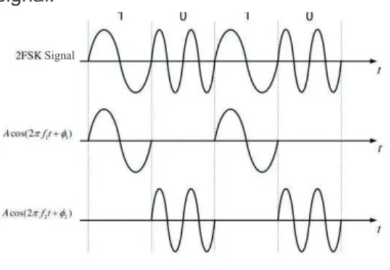
the current mainstream digital signal modulation technology, compared with their respective technical characteristics, the FSK (frequency shift keying) digital modulation for wireless transmission of data is adopted. The frequency shift keying FSK digital modulation accepted by the International Telecommunication Union is widely used in the field of network transmission. It has the characteristics of mature and reliable, the weak signal crosstalk ability, the small radiation power and the short channel setting time and so on.
FSK (frequency shift keying) modulation technology is the frequency of sine wave controlled by digital signal, so that the frequency of sine wave vary with digital signal. The mathematical expression of the FSK signal is:
)
2
cos(
)
(
t
A
m
ft
0t
S
M
)
0
;
M
3
2
1
(
m
ǃ
ǃ
ǃ
ˈ
t
T
, Wheref
is the frequency difference between M frequencies.The binary FSK signal is the sine wave of two different frequencies F1 and F2 corresponding to the "1" and "0" of the digital signal.
Signal
Figure 1 Binary FSK signal waveform diagram
3.3 Design of rotor load test system
The rotor load testing system mainly includes data acquisition and telemetry unit,
system installation disk, power supply unit and telemetry data receiving unit, Ethernet data extraction system and data monitoring on ground and on board. The system principle block diagram is shown in Figure 2. The data acquisition and telemetry unit complete the collection, modulation and wireless transmission of the load data. The customized system installation plate is the installation carrier of the data acquisition and telemetry unit. The installation disk has the installation base of data acquisition and telemetry unit and the related circuit of signal transmission and power supply. The power supply unit is supplied with double redundancy power supply, telemetry data receiving unit demodulates the received load data and sends it to the airborne networked data acquisition system in analog and Ethernet mode.
Data Acquisition and Telemetry Transmitter Module 1
Data Acquisition and Telemetry Transmitter Module 2
Telemetry signal merge module
Data Acquisition and Telemetry Transmitter Module 8
Main control module Power module Telemetry disk˄Rotating parts˅
Telemetry reception and data demodulation module 1 Telemetry reception and data
demodulation module 2
Telemetry signal merge module
Telemetry reception and data demodulation module 8
Control port Telemetry receiver˄Fixed parts˅
Transmit
antenna Receiveantenna amplification unitTelemetry signal
Collector ring Ethernet DAC module
System power supply unit Special configurationdevice Airborne data acquisitionsystem
. . . . . .
Figure 2 Principle block diagram of rotor load test system
3.3.1 Signal acquisition and processing unit The data acquisition and processing unit is designed as shown in Figure 3.
$ ' )3*$ ¦ $ ' ¦ ' 5) ' 5) )3*$ $ ' /RZSDVV $ ' /RZSDVV
Figure 3 Signal acquisition table and processing
According to the accuracy requirements of the strain data, the strain data acquisition is designed with high precision constant
current source circuit, which can effectively reduce the nonlinear error of the circuit design and ensure the accuracy of the measured data. Each strain sensor can provide high precision current independently, and the user can set the current value. The sensor signal is amplified by an amplifier and then transformed by A/D. The processor (FPGA) converts the received A / D data and forms a serial data stream. The serial data stream is modulated and amplified by FSK (frequency shift keying) modulation technology. The carrier frequency can be set by the user to avoid interference with the original wireless signal.
The receiving antenna sends the received modulation signal to the receiver for demodulation. The receiver can filter the different channel signals according to the user's requirements, and the processed signals will be output to the general airborne acquisition system in the type of Ethernet or analog.
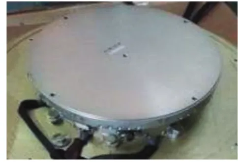
3.3.2 Design of system installation disk The system mounting disk is the installation carrier of the rotor load test system. According to the requirement of the load test, the system installation disk needs to install signal acquisition and wireless transmitting module, double redundant power control module and backup battery package for strain signal acquisition, modulation and wireless transmission.
Due to the special structure of the rotor hub mounting bracket, the system mounting disk is specially customized according to the rotor hub structure. In particular, the weight and structural strength of the equipment
have special limitations. Through the relevant technical coordination in the early stage the design of the system installation disk adopts end face mounting and disc shape design. The installation disk is designed by using the mounting screws of the rotor hub with rain cover. The center is designed as a disc platform for mounting the telemetry disc. As shown in Figure 4.
Figure 4 System installation disk The signal acquisition and wireless transmission module includes four functions of strain sensor power supply, signal conditioning, signal conversion and radio frequency transmitting. The module synchronizes all channels, the signal conditioning unit filters the input signal, the A/D converter oversampling it, and FSK (frequency shift keying) digital modulation to the sampled digital signal, and transmit it to the corresponding receiver by wireless communication.
Telemetry disk technical specification: Signal input: strain;
Number of channels: 80;
Sensor excitation: constant current ; Source excitation: 0mA to 10mA programmable;
Measurement range: 8 range adjustable; Signal bandwidth: DC to 19kHz (can be set);
Linearity: + 0.2% F.S.
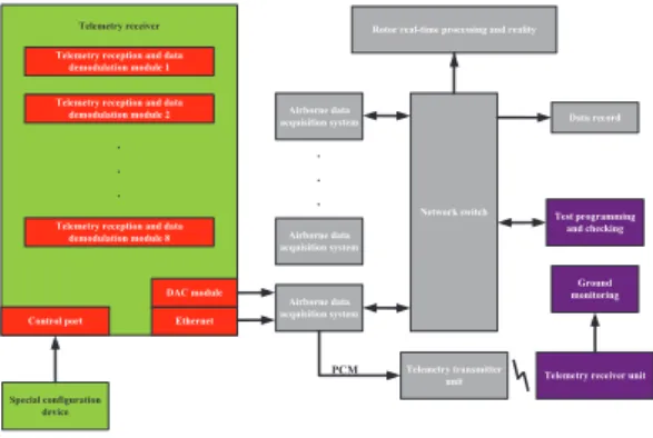
3.3.3 Data extraction and security monitoring In order to meet flight test requirements of safety monitoring, the helicopter rotor load testing system needs to transmit the rotor system load test data to the ground monitoring station and the pilot, providing a discriminant data for the flight safety. The telemetry receiver is inserted into the airborne network data acquisition system with analog connection and Ethernet communication, through the Ethernet extraction technology and then through the airborne telemetry system the load test data is sent to both the ground for safety monitoring station and the test pilots at the same time. As shown in Figure 5.
Telemetry reception and data demodulation module 1 Telemetry reception and data
demodulation module 2
Telemetry reception and data demodulation module 8 Control port Telemetry receiver Ethernet DAC module Special configuration device . . . Airborne data acquisition system Airborne data acquisition system Airborne data acquisition system Network switch Rotor real-time processing and reality
Data record
Test programming and checking
Ground monitoring
Telemetry receiver unit Telemetry transmitter unit PCM . . .
Figure 5 Data extraction and security monitoring
3.4 Laboratory debugging and verification
For the design of load test system, time synchronization is the key technology. The time delay of each channel and the time
synchronization among channels is
important to data analysis based on time history. The system uses IRIG-B time protocol to synchronize the processing units of the system, and the time synchronization accuracy design specification is 1 ms. Collecting and configuring each acquisition
channel through Ethernet, loading the programmed software to the rotor load test system. The airborne telemetry data receiving unit monitors the running state of the whole system, checks the time synchronism of each acquisition node of the whole test system, and finally guarantees the rotor load test system to meet the design specification.
3.4.1 Synchronization error test of acquisition channel
For the process of sampling, modulation, transmission, reception, demodulation and two sampling of different channel strain signals, the synchronization error between the channels is related to the requirement of the time correlation of the later data processing to the parameters.
The test results show that the synchronous interval is 940ns.
3.4.2 Time delay test of acquisition channel The time delay of the test system mainly includes signal amplification delay, filter delay, A/D conversion delay, D/A conversion delay, wireless transmission delay, processing and buffer delay, etc. Two acquisition channels are chosen, by using the same standard signal source as input and a high precision oscilloscope to test the signal waveforms of the two channels to analyze the response time of the input signals and output signals of the two channels, the time delay of the two acquisition channels can be tested, which is the time delay of the load test system. The test results show the system delay 0.94mS
4. Conclusion
By using the key technologies such as multi-channel wireless communication and
dual redundancy rotating parts power supply, the seamless connection of the test system between rotating parts and static components during the high-speed rotation of the rotor is successfully realized, and a practical rotor load test scheme is provided. The technical scheme is stable and reliable,
and it has been successfully applied at the present. The rotor load test data is accurate and reliable, and the real-time safety monitoring of the rotor load is realized for the first time. This technology has a certain reference and impetus for future helicopter rotor load test.
Reference
[1] Zhang Xiao Gu. Helicopter dynamics design [M]. Aviation Industry Press, 1995.
[2] Yang Yong. Design and implementation of spacecraft control system based on PD control. [J]. computer measurement and control, 2014.
[3] Zhao Yaxing. FPGA principle, design and application [M]. first edition. Tianjin: Tianjin University press, 1999, p36-38.
[4] Helicopter Main Rotor Telemetry User ManualˈTelemetrie Elektronik GmbH.