LyFi
Kianoosh.Salami Justin.Cotton Elush.Shirazpour
Advisor: Bryan.Mealy
Senior Project
ELECTRICAL ENGINEERING DEPARTMENT
COMPUTER ENGINEERING DEPARTMENT
California Polytechnic State University
San Luis Obispo
ABSTRACT
This paper will cover the steps necessary to design, build, and manage networkable smart
light switches over WiFi via a mobile application. It contains a microcontroller running a
real time operating system, a WiFi module, a Java server with SQLite databasing, and a
mobile phone application.
LyFi is designed to turn on/off and dim household lights while only requiring the same
installation procedure as a less capable dimmer switch. Once installed and connected to a
network, LyFi will self-discover and configure. The server automatically propogates a
database of nodes where any mobile device running an application can receive an
updated controlable list. Finally, LyFi’s hardware is not limited to only dimming lights, it
can be modified to control other applicances.
TABLE OF CONTENTS
Page
Acknowledgements...5
I.
Introduction...6
II.
FreeRTOS Integration...7
III.
Hardware and Firmware...8
IV.
Server ...19
V.
Android Mobile Client ...27
VI.
Conclusion ...31
VII.
References ...33
APPENDIX A: Hardware Schematic / PCB Layout ...34
APPENDIX C: Source Code ...39
APPENDIX D: Analysis of Senior Project Design ...96
LIST OF FIGURES
1.
Figure Overall System Block Diagram ...7
2.
FreeRTOS Hardware Configuration ...8
3.
Figure Zero-Crossing ...9
4.
Figure AC Slicing …...9
5.
Figure Dimmer Flow ISR Flow Chart ...11
6.
Figure Encoder Pin Diagram ...11
7.
Encoder Filtering Circuit ...12
8.
Encoder / Switch ISR Flow Chart ...13
9.
Hardware Initialization Flow Chart ...13
10.
WiFi Command and Parser Flow Chart ...15
11.
SQLite Entity Relationship Diagram ...21
12.
SQLite Database ...22
13.
Node Server Connection Initialization ...23
14.
Server Mobile Connection ...25
15.
Server State Diagram ...26
16.
Screenshot of Mobile Application ...28
17.
Client Diagram ...30
ACKNOWLEGMENTS
This senior project would not have been possible without the support of many people. We
would like to express our gratitude to our advisor Bryan Mealy who was abundantly
helpful and offered invaluable assistance, support, and guidance. We would also like to
thank Downtown San Luis Obispo for allowing us to hold many late night meetings and
providing tasteful refreshments.
INTRODUCTION
Our senior project aimed to create a device that can be controlled/managed via WiFi
connection. We wanted to create hardware capable of connecting to a variety of
electronic devices and allowing the user to control that device remotely with a phone
application. We choose to use WiFi since it can be found in almost all homes or
businesses in the United States as well as the rest of the world.
Before entering this project, we knew that we needed to have a WiFi module,
microcontroller, server, and a mobile application to have a successful product. We
created a PCB capable of dealing with voltages up to 120V and supply DC voltages to the
microcontroller and WiFi module. We chose the ATMega 328P microcontroller which
runs a real time operating system that allows the processor to easily switch between
different tasks. Tasks in our RTOS included the parser, switch, and encoder.
The server also runs SQLite to log all node and mobile client connections created. We
also needed to open a connection port between the server and WiFi module. To ensure
successful message passing, a UDP packet broadcasts to find the server. Once found, a
TCP socket connection between the server and WiFi module happens. Once that
completes, a parser initializes to allow the WiFi module and microcontroller to interpret
commands with one another. The microcontroller sends commands to the WiFi module
to perform various actions.
The next step was to create an application to control the selected device via WiFi. The
application communicates with the server and can send values to the WiFi module via the
server. All these parts of the project were considered with the “end user” in mind. We
wanted the project to be easy to set up, use, and troubleshoot by anyone. We also took
size in consideration and created hardware as small as possible to allow the boards to fit
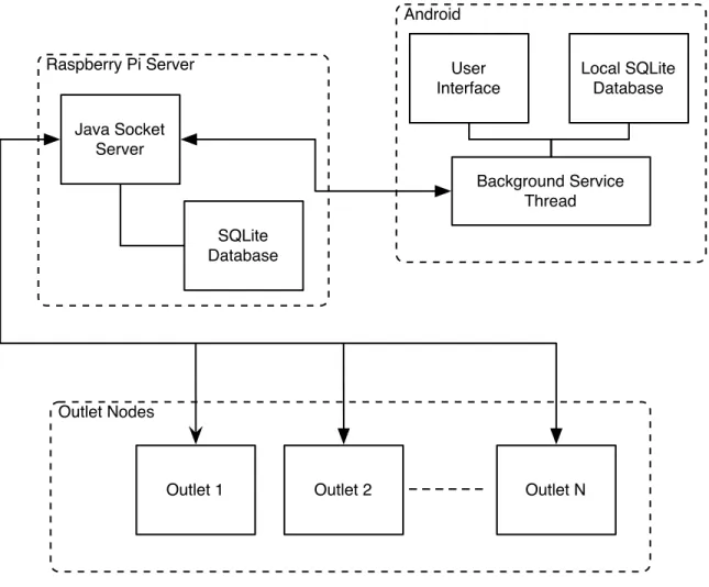
in a standard (1-gang) electrical box. The following describes the intricate details
involving each aspect of the senior project. See figure 1 for the overall block diagram.
Figure 1 Overall System Block Diagram
FREERTOS INTEGRATION
FreeRTOS is a real-time operating system for embedded devices. We choose to use a real
time operating system because it allows multiple processes to run
simultaneously
, to
perform simple task switching, and to have the ability to save data in queues.
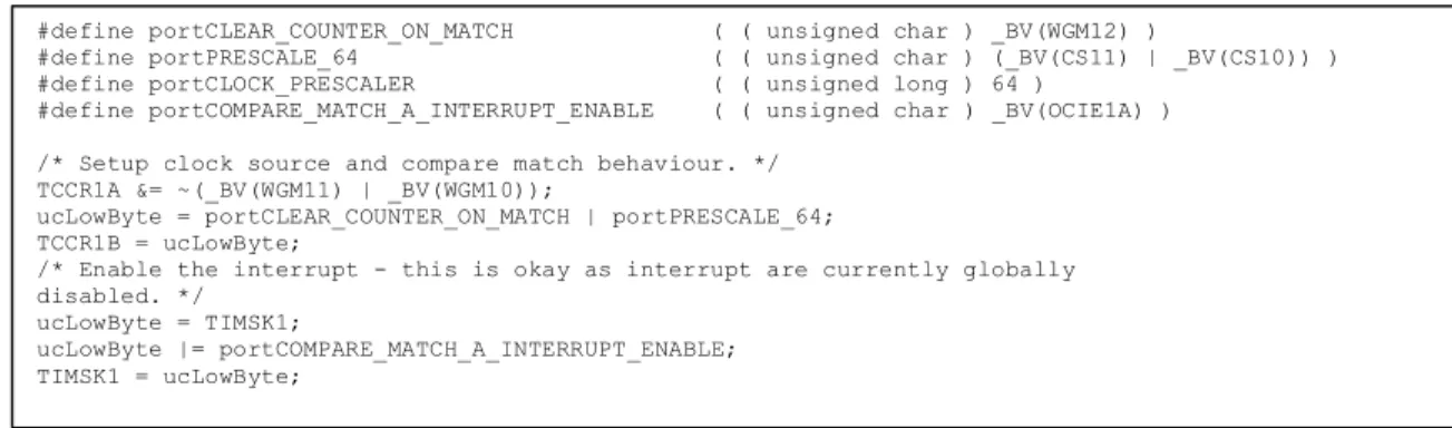
FreeRTOS’ scheduler relies on ‘ticks’ for keeping track of time; a hardware timer
controls these ticks. We utilize the 16-bit timer. The FreeRTOS source files allow
relatively easy porting. The only file needing adjustment is port.c. The modified macros
and registers are below, figure 2.
Raspberry Pi Server
Android
User
Interface
Local SQLite
Database
Background Service
Thread
Java Socket
Server
SQLite
Database
Outlet Nodes
Finally, in
FreeRTOSConfig.h
the heap size must be adjusted to the corresponding
SRAM size of the MCU. The Atmega328p has 2K (same as the Atmega323) of available
SRAM therefore
configTOTAL_HEAP_SIZE
remains
1500
.
HARDWARE AND FIRMWARE
The goal of this project is to design hardware that can easily fit in a standard (1-gang)
electrical box; consequently hardware size is a major priority. The microprocessor we
choose is an Atmel Atmega328p as we had experience with Atmel chips utilizing
FreeRTOS, its availability, and small footprint.
The next major hardware device is the WiFi chip. After much research, we decided on
the GainSpan GS1011M WiFi module. The module is specifically designed to add WiFi
to embedded systems where a complicated network stack is beyond the scope of the
hardware. All communication between the WiFi module and MCU is over USART using
specific AT (attention) commands. This allows executing complicated tasks (connecting
to networks, enabling encryption, sending/receiving packets) via simple strings. The
hardware used to switch and dim an AC light-bulb is explained in the dimmer section.
Finally, to power the embedded devices a small and efficient AC/DC 3.3V converter is
needed. We picked a Recom RAC01-3.3SC switching regulator as it requires no external
components, runs cool, and is sealed in a relatively small package.
#define portCLEAR_COUNTER_ON_MATCH ( ( unsigned char ) _BV(WGM12) )
#define portPRESCALE_64 ( ( unsigned char ) (_BV(CS11) | _BV(CS10)) ) #define portCLOCK_PRESCALER ( ( unsigned long ) 64 )
#define portCOMPARE_MATCH_A_INTERRUPT_ENABLE ( ( unsigned char ) _BV(OCIE1A) ) /* Setup clock source and compare match behaviour. */
TCCR1A &= ~(_BV(WGM11) | _BV(WGM10));
ucLowByte = portCLEAR_COUNTER_ON_MATCH | portPRESCALE_64; TCCR1B = ucLowByte;
/* Enable the interrupt - this is okay as interrupt are currently globally disabled. */
ucLowByte = TIMSK1;
ucLowByte |= portCOMPARE_MATCH_A_INTERRUPT_ENABLE; TIMSK1 = ucLowByte;
DIMMER HARDWARE
Original dimmers diverted energy into an
adjustable resistor to decrease the power
given to a load. This method is not only
inefficient, but dissipates a great deal of
heat. Modern dimmers switch power on/off
at high speed decreasing the amount of total
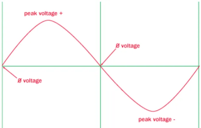
available energy. To prevent flickering the
light-bulb power needs to be switched off at
the same time as the AC’s wave
zero-crossing, (figure 3) then turned on after a small delay (figture 4). The longer the delay,
the less slice of AC energy is available to the light bulb, thus the dimmer the light
appears. No delay after a zero crossing results in full brightness.
Figure 4 AC Slicing
There are two important circuits required: one for giving zero-crossing feedback to the
microprocessor, and a second to safely switch AC power on and off (see APPENDIX A).
The zero-cross circuit works by feeding the AC source into resistors to drop the voltage.
Next the AC signal is fed into a full bridge rectifier and converted into a DC signal. The
DC signal is fed into a 4N25 optocoupler where a phototransistor is switched on an off.
The source of the transistor is fed into the microprocessor in parallel with a pull-up
resistor with the drain of the transistor is connected to ground. When the AC voltage is
not 0V the transistor is on, bringing the zero-cross signal to 0V. When the AC voltage
passes through the zero crossing, the voltage is 0V into the optocoupler LED, turning off
the transistor. There is no path to ground, and therefore no voltage drop across the pull-up
resistor resulting in VCC on the zero-cross signal. This circuit provides a nice digital
zero-cross detector and is connected to an interrupt-enabled pin, (see APPENDIX A).
To control the AC load digitally, we used a similar isolation circuit. The digital signal is
fed into a MOC3021 optoisolator with triac out. Similar to the zero-cross circuit, when
VCC is fed into the optoisolator the triac is turned on. The triac output controls a beefier
BT136 triac capable of 4A.
FIRMWARE FOR DIMMER
Originally we used software delays to turn on and off the triac, however they were
unreliable. We changed to use minimal software and timer0 in compare match mode our
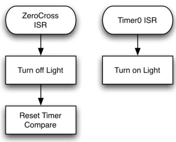
delays. When the circuit detects a zero-crossing interrupt (figure 5), the triac is turned off
and the timer count is reset to zero. Once the timer count is equal to the compare register
it triggers a separate ISR turning on the triac. These two ISRs simply slice of an AC
signal allowing the light-bulb to dim.
Figure 5 Dimmer Flow ISR Flow Chart
ENCODER
To control the light without the use of the mobile application, we used a rotary encoder,
A rotary encoder is an electro-mechanical device that converts the angular position to
digital code, called gray code. A potentiometer is limited in how many times it can be
spun in one direction. An encoder was chosen instead of a potentiometer since we knew
the application can also change the dimmer value. The encoder can change the value of
the dimmer value relative to the app. The encoder can be pushed, like a switch, or rotate
endlessly either clockwise or counterclockwise. For the senior project, pushing the
encoder in will turn on/off the light and spinning it will cause the dimmer to
increase/decrease light intensity. The encoder works by sensing are two signals, A and
B, when spinning the encoder. Spinning in a certain direction causes a switching to occur
(figure 6).
Figure 6 Encoder Pin Diagram
ZeroCross
ISR
Turn off Light
Reset Timer
Compare
Timer0 ISR
An interrupt service is called every time the encoder is spun. This interrupt activates a
binary semaphore, in which the task is unblocked. As the encoder is being spun, its value
is sent straight to the timer compare register, which is the dimmer value.
An interrupt was also created for every time the encoder switch is pushed. The interrupt
would activate a binary semaphore, in which the task would be unblocked. Pushing it
would either turn on/off the light.
An initial issue with the encoder controlling the dimmer value was that the values
decrypted from the gray code would not cause a smooth transition for the dimmer value.
Spinning the encoder too quickly would cause the encoder to freeze or skip values in
between. To deal with this, a filtering capacitor was added (figure 7).
Figure 7 Encoder Filtering Circuit
The circuit was found on the encoder’s datasheet and really helped. Spinning the encoder
with the filtering capacitor made changing the dimmer value of the light significantly
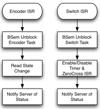
smoother. Figure 8 shows the encoder and switch block diagram.
Figure 8 Encoder/Switch ISR Flow Chart
HARDWARE INTIALIZATION
When the hardware powers on, the firmware checks if it setup for relay mode, or dimmer
mode. Once hardware is initialized, each of the tasks is initialized, ending with starting
the FreeRTOS scheduler. Figure 9 shows the flow chart for the initialization.
Figure 9 Hardware Initialization Flow Chart
Encoder ISR
BSem Unblock
Encoder Task
Read State
Change
Switch ISR
BSem Unblock
Switch Task
Notify Server of
Status
Enable/Disable
Timer &
ZeroCross ISR
Notify Server of
Status
Power On Initialize Dimmer Initialize EncoderInitialize Switch Create Parser Task Create Switch Task Create Encoder Task Start FreeRTOS Kernel Dimmer or Relay?
Relay
Dimmer
Connect to WiFi NetworkPARSER
The parser first starts when the Atmega 328P receives data from the USART. Data from
the USART is then placed into a serial queue and each byte from the queue is sent to the
parser program. Data from the USART is never lost due to the microcontroller’s ISR
which pauses any progress done in the parser program to place new USART data into the
serial queue. Figure 10 shows the parser flow chart.
void makeBuf(unsigned char byte)
Each individual byte from the serial queue is placed into a function called
makeBuf
.
makeBuf
is a multipurpose function in which it inserts certain bytes into a static array,
called buf, and counts the length of the array. Due to RAM limitations, the array stores
these bytes in the EEPROM. Before elements are stored in the array,
makeBuf
looks for
the bytes Return, or ASCII 0x0D, and Newline, or ASCII 0x0A, in succession. The WiFi
module always adds the Return and Newline before and after new data it receives. Once
that occurs,
makeBuf
will record every byte in between into
buf
. The array continues
to take in data until it records another
Return
and
Newline
in succession. Once this
occurs, the array will only contain the bytes between the two pairs of Return and
Newline. The program will continue into the function parser.
Figure 10 WiFi Command and Parser Flow Chart
void parser()
The parser function, in the parser task, determines what if the information in buf is a
packet or not. If it is a packet, the buf’s first two elements should be the ASCII values of
Escape, 0x1B, and S and the buf’s last two elements should be the ASCII values of
Escape, 0x1B, and E. If this is the case, the program continues to a function called
serverPacket
. If this was not the case, the function continues onto a function called
sendStateCheck
.
Read Serial
into Buffer
CRLFx2?
Parser
Packet?
Decode Packet
Execute
Command
SendState
Corresponding
Decoder
Set Dimmer
Level
Switch Light
On/Off
Yes
No
Yes
No
Yes
Task
Blocked?
No
Send
Command to
WiFi
Block Buffer
Task
Unblock
SendState
SendState
Unblocked
SetSendState
Write Command
to WiFi
Unblock
Buffer
Yes
void serverPacket()
serverPacket is function created to decode the message sent by the server. We created a
certain format so we would be able to distinguish and interpret a message sent by the
server. The format is decribed below:
byte 0: <ESC>
byte 1: <S>
byte 2: CID
byte 3: <$>
byte 4: ACTION
byte 5: LEN
byte 6-134: DATA
second to last byte: <ESC>
last byte: <E>
To explain in further detail,
<ESC><S>
and
<ESC><E>
are the first and last two bytes
so that the parser can distinguish that this data is a server packet. CID represents the
connection ID. It is the ASCII value of the connection ID created earlier. For example the
ID 0 will be the ASCII value 0x30. The CID is obtained from the WiFi module to
distinguish from different connections the WiFi module may have.
<$> is the special identifier so that we know the data received was certainly sent by our
server.
ACTION represents the action the server would wish to take. The options are
acknowledgment, connection, state, and type. Acknowledgment is represented with the
character A. Connection is represented with the character C. State is represented with the
character S. Type is represented with the character T. LEN represents the length of the
upcoming data sent by the server. The ASCII value of the len is sent, much like CID.
DATA represents the data that server wished to send to the microcontroller. Data can
range from the dimmer value to be sent to the light or an on/off signal to be sent to the
light.
serverPacket
verifies that the data in the buf array has all the elements needed to be
considered a correct message from the server. Since I know the correct format of a server
packet, I know where each element should be located in the buf array. The function first
records the second byte in buf, or the CID, in a local variable. The function then checks
that the third byte is the same as the identifier. If the third byte of buf does not equal the
server’s identifier, the function returns back to the beginning of the parser program. That
identifier is absolutely necessary to move forward with a server packet. If the byte is the
identifier, it then checks the next byte to see what server action is being asked for. It will
record the server action in a local variable. Data is all that is left in the packet. The
length is captured from the fifth byte. The function moves onto another function called
exec with the CID, ACTION, and LEN of the sever packet.
void exec(int cid, unsigned char servAction, int len)
exec
is the function that executes the command sent from the server. Based on what the
servAction is, it looks at the data sent by the server to perform the correct action for the
correct CID. The function first starts of with a switch statement. The switch statements
checks that the
servAction
is either acknowledgment, connection, state, or type. If it
is neither of these, the data is ignored and the function will return to
makeBuf
with no
changed made.
If the
servAction
is an acknowledgment, then we know that the data sent by the
server is to switch light on/off or set the dimmer value. We check to make sure the
len
is
2, one byte for on/off and another byte for the dimmer value.
void sendStateCheck ()
sendStateCheck
function is the function called by the parser function if the data in
needed to be called by the WiFi module to connect, send data, or close connection with
the server. Based on the value of the sendState variable, a command is sent to the WiFi
module. All WiFi commands are string literals stored in the EEPROM. EEPROM was
used instead of program space due to RAM constraints. Based on the WiFi command, a
certain response is expected to determine if the command was successful or not. A mutex
semaphore unblocks the buffer allowing the decoder to interpret feedback. When a WiFi
command returns, the buffer is then blocked, and the next command can be sent. The next
sendState
value is set and another command is sent to the WiFi module and the buffer
is unblocked.
encoder(int cid, char* str)
The encoder function was used as a way to send commands to WiFi module to send to
the server. By sending in the cid and the string implementing a certain command, a
Return character was placed at the end. The reason for this was so that the WiFi module
will execute the command. One specific command that was used was to let the server
know the WiFi module was a node. The command for this was:
byte 0: <ESC>
byte 1: <S>
byte 2: CID
byte 3: <$>
byte 4: <T>
byte 5: <4>
byte 6-134: “NODE”
byte 7: <ESC>
byte 8: <E>
This command was sent from the WiFi module to the server to let the server know the
WiFi module will be acting as a node, as opposed to a mobile client.
PCB LAYOUT
The PCB layout was done in Eagle CAD; APPENDIX A shows the schematic and layout.
The ISP header is used to program the Atmega328 microprocessor. The GP27 jumper is
used to update the firmware of the WiFi chip. Finally, the RX and TX connecting the
microprocessor and WiFi chip have jumpers, these serve two purposes. First the WiFi
chip firmware is updated through the RX and TX channels, but most importantly the
jumpers allow the serial signals to be connected to a console for easing debugging. The
various passive components utilized 0805 surface mount parts as they are small, but still
can be soldered by hand.
SERVER
The original design of this project didn’t contain a central server; however, after careful
consideration and planning, we decided it would be beneficial to have a central hub for
node and mobile connections. By implementing a server, a new mobile client could
easily control each of the outlet nodes without having to re-initialize everything all over
again. The server will hold a database of all connections, both outlet nodes and mobile
clients, as well as maintain socket connections between itself (the server) and the nodes
mobile clients.
We chose to use the
SQLite
engine to manage our database of all the node and mobile
client connections.
SQLite
offers several key advantages: lightweight - less powerful
hardware could be used for the server, multi-platform - this would allow us to choose our
server hardware later as well as testing and debugging would be much easier because we
could test on our own computers, and serverless - this makes creating and maintaining the
database very easy to do.
The server code was written in
Java
because it is multiplatform (again, we didn’t make a
final decision on the server hardware), and it is simple to perform UDP and TCP socket
connection. Another big reason was for easy compatibility between the server and the
Android mobile client, which is also written in
Java.
This doesn’t mean that using a
Java
server won’t allow for communication between other mobile operating systems, it just
made communication a lot easier.
As far as server hardware, we initially chose to use
Raspberry Pi
, which is an ARM
processor running Linux and uses an external SD card for storage. It has network access
via Ethernet which was a requirement for socket communication. However, this was a
newly released product and a shipment date could not be guaranteed. Since our server
would be able run on various platforms, we could develop, debug, and test it on a
computer and then run it on the
Raspberry Pi
when it arrived.
SQLite Database
Figure 11 SQLite Entity Relationship Diagram
Figure 11 shows the basic schema for the database.
Each
System
represents a house,
which contains several
Outlets
and can be controlled by several
Remotes.
Each
Outlet
consists of an
ID,
which is used to simply identify a node in the database. A
MAC
Address
is also used to identify a specific node as well as to guarantee that no node gets
duplicated in the database. This helps for when the node receives a new IP address from
a router’s DHCP. The node’s
IP Address
is used for debugging and testing to make sure
the node is on the same network. The
Type
is used to determine if the node is a
“dimmer” or a simple “relay.” Which helps when the mobile application draws its view
on the screen. The
Name
is just an arbitrary name for the outlet, like “Bryan’s
bedroom.” This also allows the mobile application to display a meaningful name for
each outlet. The
Status
simply indicates whether the outlet is ON (“1”) or OFF
System
Outlet Entity
ContainsMAC
Address
IP
Address
ISA
n
1
disjoint
Dimmer
Relay
Controlled byRemote
IP
Address
1
n
id
type
name
status
dimmer
value
OS type
(“0”). The
Dimmer Value
represents brightness of the light; obviously this is only used
when the
Type
is a “dimmer.” Both the
Status
and
Dimmer Value
attributes get changed
when the user physically presses the switch on the outlet or changes its status from the
mobile application. Lastly, each outlet node must only be considered as either a
“Dimmer” or “Relay.” Figure 12 shows is the code necessary to create a SQLite database
with the attributes described before.
The mobile application is treated as the
Remote
in this configuration and each
Remote
has
the ability to control all of the nodes in the
System.
The
Remote is simple;
it has an
IP
Address
to identify each
Remote
and an
OS Type
to differentiate the software on the
mobile device. The last attribute would be used for the addition of other mobile apps (ie.
Apple’s iOS)
In order for the server to communicate with the database and perform queries, a
SQLite
JDBC driver is required. This Java driver allows the server to make Java method calls
which are executed just as if it is making native SQL queries or transactions. The server
needs this driver in order to query the database for the entire node list as well as update
out-of-sync nodes and mobile clients.
CREATE TABLE nodedetails (_id INTEGER PRIMARY KEY ASC,
_type TEXT NOT NULL,
_name TEXT,
_status INTEGER,
_dimVal INTEGER,
JAVA SERVER
In order for any server-node communication, each outlet node first has to connect to the
local wireless network (see Conclusion). Next, the outlet node has to go through a
connection initialization so it can communicate with the server, see figure 13.
Figure 13 Node Server Connection Initialization
First, the server must perform its own setup process. This consists of opening up an
available local TCP socket. The port number for this TCP socket is unknown. We did
not choose a specific port since we would be performing a service broadcast from our
clients anyway; this is similar to how SMB, Bonjour, etc perform service
Server
Open up TCP socket Open UDP socket on port
52937 Node Hardware Initialization UDP broadcast at port 52937 Receive node handshake
Validate and respond with IP address and TCP port
Validate server response Parse response for server's IP
and TCP port
Connect to servers TCP socket Accept connection on TCP
listening socket Request "type" from client
Respond with "node-type" and
current status Parse TCP packet for
node's MAC address
Is MAC already in the database?
Update database entry with new IP
and status
Add node to database
Ack to node that everything is "a-ok" Receive ack, connection initialization is done Connection established yes no
discoveries. Once the TCP socket has finished, a UDP socket is opened and with known
port of 52937. We randomly chose this number seeing as no popular services uses this
port and it is not a reserved port. Since server constantly listens on both ports to accept
broadcasts and socket connections and both actions block, each is on its own thread.
After hardware initialization, the outlet node performs a UDP broadcast with a
destination address of
255.255.255.255
and port of 52937. This sends a datagram to
every device on the network on port 52937. Most likely our server is the only device
which is listening on UDP 52937. If there were other devices, it wouldn’t be an issue
since we perform some light handshaking. The UDP datagram consists of our secret
handshake of “JKE.” The server validates this handshake and responds with another key,
“EKJ” as well as the IP address and TCP port of the server. This might seem like a bit of
overhead, but it was the best approach when not knowing the IP address or TCP port of
the server. In reality, most people don’t know each port number their IP address and
even then, the router’s DHCP sometimes changes a device’s IP address.
The node then receives the server’s response, validates it, and parses the datagram for the
IP address and TCP port. Now it opens a TCP connection and attempts to bind to the
server’s TCP socket. On the server end, the TCP socket accepts the connection, spawns a
new “client decider” thread (so that other connections can still connect to the listening
TCP port), and asks the node, “what type are you?” The node responds with its own
type: “node-type.”
The server realizes the potential client is a node and spawns a “node helper” thread. It
then looks at the node’s MAC address and queries the database to see if it is already a
new node or a duplicate. If it is a new node, it simply adds the node with the necessary
attributes to the database. If the MAC address is already in the database, the server
simply updates the specific node (tuple) with new IP address, etc. Lastly, the server sends
an
ack
back to the node indicating it has successfully established a
sockets. This is necessary in order to maintain an open stream between the node and
server.
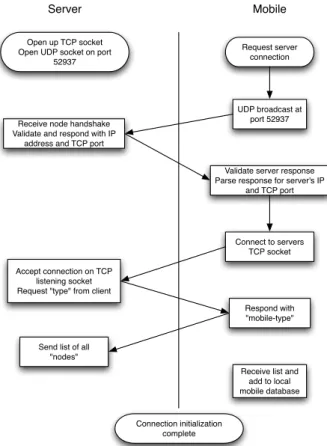
Figure 14 Server Mobile Connect Initialization
Figure 12 shows that the mobile client also performs a similar server connection
process. By this point, the server has already gone through its setup process, as
previously described. The mobile client broadcasts, the server responds with its own IP
address and TCP port, and the mobile client then connects. When the mobile client
responds to the server with the type: “mobile-type”, the server spawns a new “client
helper” thread and adds this mobile client to a list of other mobile clients. Then the
server queries its database and sends a list of all nodes and each of their statuses to the
mobile client. This way, the mobile app is completely updated just as if it has always
been connected to the system. The server-mobile client initialization is completed and
now the system is ready tfor total communication.
The server does not only perform connection initialization, but it also allows for
system-ServerOpen up TCP socket Open UDP socket on port
52937 Mobile Request server connection UDP broadcast at port 52937 Receive node handshake
Validate and respond with IP address and TCP port
Validate server response Parse response for server's IP
and TCP port
Connect to servers TCP socket Accept connection on TCP
listening socket Request "type" from client
Respond with "mobile-type"
Send list of all "nodes"
Receive list and add to local mobile database
Connection initialization complete
wide communication: directing nodes to turn on or off and update the user interface on
the mobile client. The state diagram (figure 15) describes the server’s main functionality.
Figure 15 Server State Diagram
After a client successfully connects and the server spawns the appropriate mobile or node
helper thread, the server waits for something to do. One action the server performs is
notifying which node to change its status (on / off or dimmer value). This action occurs
when mobile remote connected to the system has been triggered to change the status of
one of the outlets from the user interface. Referring
SQLite
attributes, the server uses the
ID
of the outlet, which is the same
ID
on the mobile side and on the server node list, to
send an on or off command to the appropriate node (see Packet formatting page 15). The
Start
End Server
failed to open server socket
/ close any open streams
listening for clients to
connect
opened server listening
socket
while true
new client connected
client connected successfully /
spawn new client thread
waiting to something
while true
change node status (ON/OFF)changed status from mobile
tell node to turn ON/OFF
perform database query
mobile requests
list of nodes
send list to mobile
update database status
notify mobile to refresh
list status
node switch
pressed and
changed status
close connectionsclient disconnects
close streams
and clean-up
database is updated with the correct status of that specific node as well as the user
interface for the connected mobile remotes.
Another possible action occurs when a user manually changes the status using the
hardware dimmer and switch. In this case the node obviously changes its status instantly,
but it also notifies the server to update the database accordingly. After, the server then
notifies all connected mobile remotes to update their statuses as well.
Performing a full database query usually occurs only when a new mobile client connects;
however, sometimes the mobile client doesn’t display the correct node statuses and it
needs to get re-synced with the server. In this case the mobile client requests a fresh new
list of all nodes. The server performs a SQL query, wraps the result in a nice list, and
sends it over to the mobile client who requested the list.
A rare action occurs when the mobile or node client closes its connection. Both type of
clients are programed to handle this event gracefully so the server must be able to do the
same. Regardless of type, the server closes any open socket streams it had with the client
and it removes it from the database.
Additionally, if for some reason the server restarts and it does so too quickly, before the
UDP sockets close, it will throw a
BindException
because it cannot open a socket on
UDP port 52937. When this occurs, the server simply closes any other open streams and
exits. Realistically, this will rarely ever happen and in that event, the user will simply
just unplug the
Raspberry Pi
.
ANDROID MOBILE CLIENT
We chose Android as the platform for the mobile client because we have previous
experience with the Android operating system and it allows for really simple socket
communication since it is also written in Java. We also had plenty of Android devices to
develop, debug, and test our mobile remote client application.
An Android application’s code runs on one main user interface (UI) thread which is
perfectly okay for simple method calls. However, socket communication, database
queries, and large operations can lag the UI and cause the application to freeze. To solve
this issue, we created a background service, which executes socket communication and
database queries on a separate thread, and a
MessageHandler
to update the UI thread
so it can display the correct up-to-date node statuses. Android also supports the use of
SQLite to store local application information, such as the UI persistence. There are other
methods to maintain UI state; however, by synchronizing the local Android database with
the main SQLite database on the server, it kept overhead overhead down and simplified
much of the code. (If you need to see more information on Android, please consult the
API (see sources), it is extremely helpful.)
Figure 16 demonstates the mobile application is relativiley simple: it consists of a list of
outlets each with a
SeekBar
to represent the dimmer value and a ON/OFF
Switch
. Each outlet has a top main and bottom sub
TextView
to represent the
naming scheme of the outlet. Under the list is the bottom half of the
ActionBar
which
contains four easy-to-access buttons: add a new outlet, refresh the current list, delete the
entire outlet list, and additional settings.
The
Switch
turns the outlet node ON or OFF. When the switch is pressed, the UI
thread notifies the background service to send a command to the server (see Parser) to
change the node’s status to the appropriate state. This allows the UI thread to be
responsive to the user while using sockets to communicate with the server on a separate
worker thread. The background service starts after the server-mobile connection is
successfully established (see the mobile client state diagram of figure 17). As previously
described, the server updates its database to reflect the change after the node’s state
changes.
The
SeekBar
controls with dimmer value of the outlet node. The seekbar’s value goes
from 0 - 240. However, the architecture of the node’s dimmer requires the maximum
value (completely on) to be 8 and the minimum value (completely off) to be 248. To
solve this, the seekbar’s value was subtracted from 248; this dimmer value was then sent
to the background service. The server is notified and the dimmer value on the node is
eventually changed. This event is triggered only when the user lifts his or her finger off
the seekbar, not while it is moving back or forth.
The
TextViews
display the appropriate name of each outlet in the list. These names
are simply for the user to identify each outlet. These names are stored in the Name
attribute in the database. These names are established when the node gets added to the
network and then connects to the server. (Please see the Conclusion to see how the outlet
gets added as well as for the “Add” button functionality.)
The refresh button makes the local application database mirror the server database.
Pressing the refresh button notifies the server that this mobile client is requesting an
update on all the nodes’ statuses. When the background service retrieves the list, it
parses it, and then updates the local database with any changes. We essentially wipe out
the local database and copy over the server’s database values. The delete button
completely erases local database of all outlet entities. The settings button takes the user
into the applications preferences. These three buttons were mainly added for debugging
and testing purposes as well as to fill in the plain user interface.
Figure 17 Mobile State Diagram
Figure 17 shows the background service also listens for socket communication
from
the
server as well. This allows the mobile client to be updated on the status of any nodes
which have been physically turned on or off with the dimmer switch. When this happens,
the server notifies any connected mobile clients to send a refresh request to the server.
These the mobile application’s local database is updated to reflect these changes. A
MessageHandler
then notifies the UI thread to update itself by calling its
OnResume()
method. This forces all the widgets (
TextView
,
Switch
,
SeekBar
,
etc) to be updated to their respective values. Please note that this does not happen
automatically; we had to add code so that the outlets’ values in the list would be pulled
from the local database. This was important to do so that all mobile clients would be on
the same page when looking at the user interface and the entire system would continue to
operate smoothly from an end user’s point of view.
Start End Server Connection connect to server waiting for something to do connection successful no Background Service Thread
wait for user input yes while true ON / OFF / SeekBar pressed refresh list of nodes UI Thread notify server to change node's status
close socket streams and connection notify service to tell server to change node status notify service to request new list
from server triggered by ON / OFF or Dimmer button request server for node list update UI to reflect node changes triggered by refresh button server notifies mobile client that node has
manually changed status
The server-to-mobile socket communication uses an
Object[Input|Output]Stream
. The
Packet
class must implement the
Serializable
interface in order to be sent across the socket stream. This allows both
the Android client and Java server to understand the packet as a Java object on both sides
of the connection. The constructor appears as shown below:
mState
is a enum which indicates the server or mobile client which action to
perform.
mEnable
is an integer which indicates the outlet’s state: ON or OFF.
mDimVal
is an integer which represents the outlet’s dimmer status.
mId
is also an integer used to
identify the outlet in the database.
mList
is the a list of outlets whose statuses are being
updated through the refresh request, or changed due to a status change.
DEMO VIDEO
A demo video can be viewed on youtube.
http://www.youtube.com/watch?v=KJWV0JlShVg
CONCLUSION
We initially planned for the outlet nodes to automatically connect to the local
network. The WiFi chip has an access point (AP) mode which allows a device to connect
to it as a client. The Android mobile client would connect to the node, which would start
in AP mode. Once connected, the application would send the SSID and passphrase to the
node. The microprocessor would store these values in the EEPROM. It would also
public Packet () {
mState = Action.DO_NOTHING;
mEnable = Outlet.OFF;
mDimVal = Outlet.MIN_DIMMER_VAL;
mId = 0;
mList = new ArrayList<Outlet>();
}
change the boot-up mode, which is also in the EEPROM, from AP mode to client
mode. The microprocessor would then reboot itself, start in client mode, read the SSID
and password values in the EEPROM, and connect to the wireless network. However,
this was not a key feature for our demonstration and decided to put it in the backlog.
The big emphasis on the server design and architecture was scalability and platform
independence. We wanted to have the ability to reliably add several different outlets and
mobile clients to our system. Also, the
Raspberry Pi
didn’t have a guaranteed shipment
date so we wanted to have the ability to use different hardware for the server, more
specifically, a laptop. We achieved this by writing the server in Java and using a simple
SQLite database. This turned out to be a good decision since the
Pi
arrived two days
before the Senior Project Expo.
Finally, the embedded hardware is not limited to controlling and dimming a light; the
firmware can easily be changed to enable remote control any other device, a gateway to
the “internet of things.”
This project allowed us to demonstrate our strengths from Electrical Engineering: PCB
design, power electronics, and hardware design, Computer Engineering: hardware
integration and firmware, and Computer Science: server design, database management,
and mobile phone applications.
REFERENCES
[1] Android,
Android Developers SDK
, June 2012. [Online].
Available:http://developer.android.com/reference/. [Accessed Spring 2012].
[2] Atmel,
Atmega328P Datasheet
, [Online].
Available:http://www.atmel.com/Images/8271S.pdf. [Accessed January 2012]
[3] FreeRTOS,
FreeRTOS API
, [Online]. Available:http://www.freertos.org/a00106.html
[Accessed January 2012]
[4] Harris, Tom.
How Dimmer Switches Work,
13 August 2002. HowStuffWorks.com
[Online]. Availalbe:http://home.howstuffworks.com/dimmer-switch.htm. [Accessed:
Janurary 2012]
[5] Oracle,
Java Platform Standard Ed. 6
, Edition of book, 2011. [Online].
http://docs.oracle.com/javase/6/docs/api/. [Accessed Spring 2012]
APPENDIX A: HARDWARE SCHEMATIC / PCB LAYOUT
LyFi HiV PCB Layout:
Embedded Board PCB Layout
APPENDIX C: SOURCE CODE
Firmware
/* FIRMWARE MAIN.C */
/****************************************************************************** * Header file inclusions.
******************************************************************************/ #include <avr/io.h> #include <avr/interrupt.h> #include "FreeRTOS.h" #include "task.h" #include "serial.h" #include "dimmer.h" #include "switchDriver.h" #include "parser.h" #include "wifi_eeprom.h" /****************************************************************************** * Private macro definitions.
******************************************************************************/ #define BAUD 9600
#define SER_BUF_LEN 25 //Serial buffer length int main(void) { /*set_wf_ssid("JeebsNet", 8); set_wf_pw("candy4myles316", 14); set_wf_mode(1); */ set_wf_ssid("Enchilada", 9); set_wf_pw("loadedquestion$77", 17); set_wf_mode(1); PORTB = 0x00;
if(DIMMER_EN) //Intialize dimmer specific components {
initialize_dimmer(); //intializes dimmer initialize_encoder();
}
xSerialPortInitMinimal( BAUD, SER_BUF_LEN); //Intialize serial port initialize_switch();
//vSerialPutString( NULL, (const signed char * const)"Run", 3 );
/* PARSER TASK */
xTaskCreate( (pdTASK_CODE) vTaskParser, NULL, 137, (void *) NULL, 2, NULL );
/* SWITCH TASK ON or OFF button */
xTaskCreate( (pdTASK_CODE) vTaskSwitchISR, NULL, 125, (void *) NULL, 1, NULL );
/* ENCODER TASK */
xTaskCreate( (pdTASK_CODE) vTaskENCISR, NULL,
configMINIMAL_STACK_SIZE, (void *) NULL, 1, NULL ); // Start scheduler.
vTaskStartScheduler(); return 0;
/* FreeRTOSConfig.h */ #ifndef FREERTOS_CONFIG_H #define FREERTOS_CONFIG_H
#include <avr/io.h>
/*--- * Application specific definitions.
*
* These definitions should be adjusted for your particular hardware and * application requirements.
*
* THESE PARAMETERS ARE DESCRIBED WITHIN THE 'CONFIGURATION' SECTION OF THE * FreeRTOS API DOCUMENTATION AVAILABLE ON THE FreeRTOS.org WEB SITE. * * See http://www.freertos.org/a00110.html. *---*/ #define configUSE_PREEMPTION 1 #define configUSE_IDLE_HOOK 0 #define configUSE_TICK_HOOK 0
#define configCPU_CLOCK_HZ ( ( unsigned long ) F_CPU ) #define configTICK_RATE_HZ ( ( portTickType ) 1000 )
#define configMAX_PRIORITIES ( ( unsigned portBASE_TYPE ) 2 ) /*was 4 changed to 2 to save sram */
#define configMINIMAL_STACK_SIZE ( ( unsigned short ) 85 ) #define configTOTAL_HEAP_SIZE ( (size_t ) ( 1500 ) )
#define configMAX_TASK_NAME_LEN ( 1 ) /* was 8 changed to 1 because desperate for sram */ #define configUSE_TRACE_FACILITY 0 #define configUSE_16_BIT_TICKS 1 #define configIDLE_SHOULD_YIELD 1 #define configQUEUE_REGISTRY_SIZE 0 #define configUSE_MUTEXES 1 /* Co-routine definitions. */ #define configUSE_CO_ROUTINES 1 #define configMAX_CO_ROUTINE_PRIORITIES ( 2 )
/* Set the following definitions to 1 to include the API function, or zero to exclude the API function. */
#define INCLUDE_vTaskPrioritySet 0 #define INCLUDE_uxTaskPriorityGet 0 #define INCLUDE_vTaskDelete 0 #define INCLUDE_vTaskCleanUpResources 0 #define INCLUDE_vTaskSuspend 0 #define INCLUDE_vTaskDelayUntil 0 #define INCLUDE_vTaskDelay 1 #endif /* FREERTOS_CONFIG_H */ /* switchDriver.h */ #ifndef SWITCHDRIVER_H #define SWITCHDRIVER_H
#define DIMMER_EN 1 //1 for DIMMER 0 for RELAY /* SEE DIMMER.H FOR RELAY PIN CONFIGURATION */ void initialize_switch();
void vTaskSwitchISR(void *pvParameters); #endif /* SwitchDriver.c */ #include <avr/interrupt.h> #include <avr/eeprom.h> #include "FreeRTOS.h" #include "dimmer.h" #include "task.h" #include "semphr.h" #include "switchDriver.h" #include "parser.h" uint8_t EEMEM sw_state; /* Enable extInterrupt INT1 */
{ \ EIMSK |= _BV(INT1); \
} #define INT1InterruptOff0() \
{ \
EIMSK &= ~(_BV(INT1)); \ }
xSemaphoreHandle switchBinSemaphor0; void initialize_switch()
{
eeprom_write_byte(&sw_state, 0x01);
/* The rising edge of INT0 generates an interrupt request.see pg73 DS*/ EICRA |= ( _BV(ISC11) | _BV(ISC10) );
vSemaphoreCreateBinary(switchBinSemaphor0);
xSemaphoreTake( switchBinSemaphor0, portMAX_DELAY ); INT1InterruptOn0();
return; }
void vTaskSwitchISR(void *pvParameters) {
//static unsigned int state = 1; //static unsigned int wifirun = 1;
/*Intialize wifi without creating a new task :) */ //intialize_wifi(); //ncloseall(); vTaskDelay(50 / portTICK_RATE_MS); connToServer(); vTaskDelay(50 / portTICK_RATE_MS); sendNodeBS(); for(;;) { /*intialize wifi */ /*if(wifirun) { intialize_wifi(); wifirun = 0; }*/ ENC_PIN = 0x08;
if(xSemaphoreTake( switchBinSemaphor0, portMAX_DELAY ) == pdTRUE) { INT1InterruptOff0(); vTaskDelay(210 / portTICK_RATE_MS); if(eeprom_read_byte(&sw_state)) { ENC_PIN = 0x08; if(DIMMER_EN) { turnOnDimmer(); } else { turnOnRelay(); } eeprom_write_byte(&sw_state, 0x00); } else { ENC_PIN = 0x04; if(DIMMER_EN) { turnOffDimmer(); } else { turnOffRelay(); } eeprom_write_byte(&sw_state, 0x01); } INT1InterruptOn0();
} } }
ISR(INT1_vect) {
static portBASE_TYPE xHigherPriorityTaskWoken; xHigherPriorityTaskWoken = pdFALSE;
xSemaphoreGiveFromISR( switchBinSemaphor0, &xHigherPriorityTaskWoken ); }
/* dimmer.h */ /*
* Dimmer driver for ATMEGA328p * Written By: Kianoosh Salami */
//
#ifndef DIMMER_H #define DIMMER_H
/* TRIAC / RELAY CONFIGURATION */ #define TRIAC_CNTL_PORT DDRB #define TRIAC_CNTL_PORTO PORTB
#define TRIAC_CNTL_PIN PB0 //TRIAC PIN OR RELAY CTRL PIN /* ENCODER DEFINITIONS */
#define ENC_CTRL PORTC #define ENC_PORT DDRC #define ENC_PIN PINC #define ENC_PINMSK 0x03 #define ENC_ENA PC0 #define ENC_ENB PC1 #define ENC_LEDG PC2 #define ENC_LEDR PC3 #define ENCODER_POSITION_MAX 245 #define ENCODER_POSITION_MIN 8 /* DIMMER SETTINGS */ #define INITIAL_DIM 10 #define DIMMER_INC 8 /* TIMER0 SETUP */
#define tim0CTC TCCR0A = _BV(WGM01); //Normal Port Operation / CTC top OCRA #define tim0ClkpreScale TCCR0B = _BV(CS02); // clk prescale 256
#define TMRCMP OCR0A //TIMER COMPARE REGISTER void initialize_dimmer();
void setDimmer(uint8_t dimmer_val); void turnOffDimmer();
void turnOnDimmer(); void initialize_encoder(); void turnOffRelay(); void turnOnRelay();
void vTaskENCISR(void *pvParameters); #endif /* DIMMER_H */ /* dimmer.c */ #include <avr/interrupt.h> #include "FreeRTOS.h" #include "dimmer.h" #include "task.h" #include "semphr.h" #include "dimmer.h" #include "serial.h"
/* Zero Cross connected to INT0 */ /* Enable extInterrupt INT0 */ #define extInterruptOn0() \
EIMSK |= _BV(INT0); \ TIMSK0 |= _BV(OCIE0A); \ }
#define extInterruptOff0() \
{ \
EIMSK &= ~(_BV(INT0)); \ TIMSK0 &= ~(_BV(OCIE0A)); \ } #define PinChgInterruptOn0() \ { \ PCICR |= _BV(PCIE1); \ PCMSK1 |= (_BV(PCINT8) | _BV(PCINT9)); \ } #define PinChgInterruptOff0() \ { \
PCICR &= ~(_BV(PCIE1)); \ PCMSK1 &= (~(_BV(PCINT8)) & ~(_BV(PCINT9))); \
}
void initialize_dimmer() {
TRIAC_CNTL_PORT |= _BV(TRIAC_CNTL_PIN); //Enable triacpin as OUTPUT /* The rising edge of INT0 generates an interrupt request.see pg73 DS*/ EICRA = ( _BV(ISC01) | _BV(ISC00) );
extInterruptOn0();
/* TIMER0 CONFIGURE SEE DIMMER.H */ tim0CTC //Normal Port Operation / CTC top OCRA tim0ClkpreScale // clk prescale 256
setDimmer(INITIAL_DIM); return;
}
xSemaphoreHandle encBinSemaphor0; //binary semaphor for encoder void initialize_encoder()
{
ENC_PORT |= _BV(ENC_LEDR) | _BV(ENC_LEDG); //Enable LED port as OUTPUT ENC_PORT &= (~(_BV(ENC_ENA)) & ~(_BV(ENC_ENB))); //Set as inputs ENC_CTRL |= (_BV(ENC_ENA)) | (_BV(ENC_ENB)); //turn on pullups vSemaphoreCreateBinary(encBinSemaphor0);
xSemaphoreTake( encBinSemaphor0, portMAX_DELAY ); PinChgInterruptOn0();
return; }
/* Set dimmer value,
* LOWER the number the BRIGHTER * HIGHER the number the MORE DIM * 1-255
*/
void setDimmer(uint8_t dimmer_val) {
if(dimmer_val > 0 && dimmer_val < 256) {
TMRCMP = dimmer_val; }
return; }
void vTaskENCISR(void *pvParameters) {
// enc_states[] is a fancy way to keep track of which direction // the encoder is turning. 2-bits of oldEncoderState are paired // with 2-bits of newEncoderState to create 16 possible values. // Each of the 16 values will produce either a CW turn (1), // CCW turn (-1) or no movement (0).
int8_t enc_states[] = {0,-DIMMER_INC,DIMMER_INC,0,DIMMER_INC,0,0, -DIMMER_INC,-DIMMER_INC,0,0,DIMMER_INC,0,DIMMER_INC,-DIMMER_INC,0};
static uint8_t oldEncoderState = 0; uint8_t newEncoderState = 0; for(;;)
{
if(xSemaphoreTake( encBinSemaphor0, portMAX_DELAY ) == pdTRUE) {
uint8_t tempENCVAL = TMRCMP; //Read TIMER Register PinChgInterruptOff0();
vTaskDelay(7 / portTICK_RATE_MS); //Software debounce newEncoderState = ENC_PIN & ENC_PINMSK;
//xSerialPutChar( serCOM1, newEncoderState, 10 ); oldEncoderState <<= 2;
oldEncoderState &= 0x0C; //Mask out all values except old oldEncoderState |= newEncoderState;
//xSerialPutChar( serCOM1, oldEncoderState, 10 );
/*-= Beacuse the lower the delay the brighter the light.*/ tempENCVAL -= enc_states[oldEncoderState];
if (tempENCVAL > ENCODER_POSITION_MAX) setDimmer(ENCODER_POSITION_MAX);
else if (tempENCVAL < ENCODER_POSITION_MIN) setDimmer(ENCODER_POSITION_MIN);
else
setDimmer(tempENCVAL);
//xSerialPutChar( serCOM1, TMRCMP, 10 ); //debug output encoder value PinChgInterruptOn0(); } } } void turnOffDimmer() { extInterruptOff0();
TRIAC_CNTL_PORTO &= ~(_BV(TRIAC_CNTL_PIN)); //Turn off Triac //ENC_PIN &= ~(_BV(ENC_LEDG));
//ENC_PIN |= _BV(ENC_LEDR); }
void turnOnDimmer() {
extInterruptOn0();
//ENC_PIN &= ~(_BV(ENC_LEDR)); ENC_PIN |= _BV(ENC_LEDG); }
void turnOnRelay() {
TRIAC_CNTL_PORTO |= (_BV(TRIAC_CNTL_PIN)); //Turn on Relay }
void turnOffRelay() {
TRIAC_CNTL_PORTO &= ~(_BV(TRIAC_CNTL_PIN)); //Turn off Relay }
// This will jump when INT0 is triggered. To be used with ZERO crossing INT ISR(INT0_vect)
{
TRIAC_CNTL_PORTO &= ~(_BV(TRIAC_CNTL_PIN)); //Turn off Triac TCNT0 = 0; //Reset timer to 0
}
ISR(TIMER0_COMPA_vect) //THIS TIMER CONTROLS THE DELAY for dimmer {
TRIAC_CNTL_PORTO |= (_BV(TRIAC_CNTL_PIN)); //Turn on Triac }
ISR(PCINT1_vect) //ISR for ENCODER PINS {
static portBASE_TYPE xHigherPriorityTaskWoken; xHigherPriorityTaskWoken = pdFALSE;
xSemaphoreGiveFromISR( encBinSemaphor0, &xHigherPriorityTaskWoken ); }
/* wifi_eeprom.h */ #ifndef WIFIEEPROM_H #define WIFIEEPROM_H
/***************************************************************************** * EEPROM SETUP FOR WIFI SETTINGS
****************************************************************************/ #define MAXWFSDLEN 33 #define MAXWFPWLEN 65 void rd_wf_pw(uint8_t* wfpw); uint8_t rd_wf_ssidlen(); uint8_t rd_wf_pwlen();
void set_wf_mode(uint8_t mode);
void set_wf_ssid(uint8_t ssid[], uint8_t len); void set_wf_pw(uint8_t pw[], uint8_t len); void rd_wf_ssid(uint8_t* wfssid);
#endif
/* wifi_eeprom.c */
/* WIFI_PARAM FUNCTIONS */ #include <avr/eeprom.h> #include "wifi_eeprom.h" uint8_t EEMEM wf_mode=0x01; uint8_t EEMEM wf_ssidlen; uint8_t EEMEM wf_wpalen;
uint8_t EEMEM wf_ssid[MAXWFSDLEN]; uint8_t EEMEM wf_pw[MAXWFPWLEN];
void set_wf_mode(uint8_t mode) {
eeprom_write_byte(&wf_mode, mode); return;
}
void set_wf_ssid(uint8_t ssid[], uint8_t len) {
eeprom_write_block((const void *)ssid, (const void *)wf_ssid, len); eeprom_write_byte(&wf_ssidlen, len);
return; }
void set_wf_pw(uint8_t pw[], uint8_t len) {
eeprom_write_block((const void *)pw, (const void *)wf_pw, len); eeprom_write_byte(&wf_wpalen, len); return; } uint8_t rd_wf_ssidlen() { return eeprom_read_byte(&wf_ssidlen); } uint8_t rd_wf_pwlen() { return eeprom_read_byte(&wf_wpalen); } void rd_wf_pw(uint8_t* wfpw) {
uint8_t wifilen = rd_wf_pwlen(); uint8_t wfstr[wifilen];
eeprom_read_block((void *)wfstr, (const void *)&wf_pw, wifilen);
//vSerialPutString( NULL, (const signed char * const)wfstr, wifilen); for(uint8_t i=0; i<wifilen; i++)
{
wfpw[i] = wfstr[i]; }
return; }
void rd_wf_ssid(uint8_t* wfssid) {
uint8_t ssidlen = rd_wf_ssidlen(); uint8_t wfstr[ssidlen];
eeprom_read_block((void *)wfstr, (const void *)&wf_ssid, ssidlen);
//vSerialPutString( NULL, (const signed char * const)wfstr, wifilen); for(uint8_t i=0; i<ssidlen; i++)
{ wfssid[i] = wfstr[i]; } return; } /* parser.h */ #ifndef PARSER_H #define PARSER_H //#define WIFIDATA 4 #define EEBUFLEN 100 #define CMDDELAY 10 #define RETURN 0x0D #define NEWLINE 0x0A #define ESCAPE 0x1B #define IDENTIFIER 0x24 #define ACK 0x41 #define CONN 0x43 #define STATE 0x53 #define TYPE 0x54
/*SEND STATE DEFINITIONS */ #define NONE 0 #define ATE 1 #define ATV 2 #define NDHCP 3 #define ATWWPA 4 #define ATWA 5 #define ATFNDSRV 6 #define ATWD 7 #define ATNCTCP 8 #define ATNCLOSEALL 9 #define ATBDCST 10 #define blkTime 10
uint8_t makeBuf(unsigned char); void vTaskParser(void *pvParameters); void connToServer(); void sendNodeBS(); void parser(); void ate(uint8_t); void atv(uint8_t); void atwd(); void ndhcp(uint8_t); void wwpa(); void wa(); void nctcp(); void ncloseall(); void sendStateCheck(); void errorCheck(); uint8_t serverPacket();
void exec(uint8_t, unsigned char, uint8_t);
void encoder(uint8_t cid, char* str, uint8_t strlen); void intialize_wifi(); void waitForResponse(); void responseReceived(); void wa_dec(); void udp_dec(); void crnl(); void broadcast(); void findserver(); #endif /* parser.c */ #include <avr/io.h> #include <avr/interrupt.h> #include <avr/eeprom.h> #include "FreeRTOS.h" #include "task.h" #include "semphr.h" #include "serial.h" #include "dimmer.h" #include "switchDriver.h" #include "parser.h" #include "wifi_eeprom.h" uint8_t idx = 0; //uint8_t check = 1; uint8_t sendState = 0; uint8_t EEMEM eebuf[EEBUFLEN];
/* THE FOLLOWING COMMANDS ARE BLACKED OUT DUE TO AN NDA SIGNED WITH THE WIFI CHIPSET COMPANY */ uint8_t EEMEM EESERV[] = BLACKOUT
uint8_t EEMEM EEPKT[] = "S0$T4NODE"; uint8_t EEMEM BLACKOUT [] = " BLACKOUT "; uint8_t EEMEM BLACKOUT [] = " BLACKOUT "; uint8_t EEMEM BLACKOUT [] = " BLACKOUT "; uint8_t EEMEM BLACKOUT [] = " BLACKOUT”; uint8_t EEMEM BLACKOUT [] = " BLACKOUT uint8_t EEMEM BLACKOUT [] = " BLACKOUT "; uint8_t EEMEM BLACKOUT [] = " BLACKOUT uint8_t EEMEM BLACKOUT [] = " BLACKOUT uint8_t EEMEM BLACKOUT [] = " BLACKOUT "; uint8_t EEMEM EE255P[] = "255.255."; uint8_t EEMEM EE255C[] = "255.255,"; uint8_t EEMEM EEPORT[] = "52937"; uint8_t EEMEM EEBRDCST[] = "S0JKE"; uint8_t EEMEM EESERVIP[21];
uint8_t EEMEM EESERVIPLEN; xSemaphoreHandle xMutexSemaphore; xSemaphoreHandle xSendState;
void vTaskParser(void *pvParameters) {
signed char recv = '0';
xMutexSemaphore = xSemaphoreCreateMutex(); xSendState = xSemaphoreCreateMutex(); xSemaphoreTake(xMutexSemaphore, portMAX_DELAY); for(;;) { xSemaphoreGive(xMutexSemaphore); xSemaphoreTake(xMutexSemaphore, portMAX_DELAY); if( xSerialGetChar( NULL, &recv, 1 ) == pdTRUE ) {
makeBuf((unsigned char)recv); }
} }
uint8_t makeBuf(unsigned char byte) {
static uint8_t CRstart = 0; static uint8_t start = 0; static uint8_t CRend = 0; if(start == 1) { if(byte == (char)RETURN) { CRend = 1; return 0; }
else if((CRend == 1) && (byte == (char)NEWLINE)) { start = 0; CRend = 0; parser(); idx = 0; return 1; }
else if((CRend == 1) && (byte != (char)NEWLINE)) { return 0; } else { eeprom_write_byte((&eebuf+idx),byte); idx++; //xSerialPutChar(NULL,byte,10); //xSerialPutChar( NULL, idx, 10 ); return 0;
} }
else if(byte == (char)RETURN) {
CRstart = 1; return 0; }
else if((byte == (char)NEWLINE) && (CRstart == 1)) { start = 1; CRstart = 0; return 0; } else { CRstart = 0; return 0; } } void parser() { uint8_t i;
if(eeprom_read_byte(&eebuf) == (char)ESCAPE && eeprom_read_byte(&eebuf+1) == 'S') {
for(i = 2; i < idx; i++) { if(eeprom_read_byte(&eebuf+i) == (char)ESCAPE) if(i+1 <= idx) if(eeprom_read_byte(&eebuf+i+1) == 'E') { //xSerialPutChar(NULL,'B',10); serverPacket(); } } } else if(eeprom_read_byte(&eebuf) == '#') { uint8_t atstr[idx-1]; uint8_t attcp[9];
//xSerialPutChar( NULL, idx, 10 ); // eeprom_write_byte(&EESERVIPLEN, (idx-1));
for(uint8_t i=1; i<idx; i++) {
atstr[i-1] = eeprom_read_byte(&eebuf+i); }
//vSerialPutString(NULL, (const signed char * const)atstr,(idx-1)); eeprom_read_block((void *)attcp, (const void *)&EEatnctcp, 9);
crnl();
vSerialPutString( NULL, (const signed char * const)attcp, 9);
vSerialPutString( NULL, (const signed char * const)atstr, idx-1); crnl();
sendStateCheck(); }
return; }
void ate(uint8_t echo) { xSemaphoreTake(xSendState, portMAX_DELAY); taskENTER_CRITICAL(); sendState = ATE; taskEXIT_CRITICAL(); uint8_t atstr[3];
eeprom_read_block((void *)atstr, (const void *)&EEate, 3); crnl();
vSerialPutString( NULL, (const signed char * const)atstr, 3); xSerialPutChar( NULL, (echo + '0'), blkTime );
crnl(); waitForResponse(); return; } void atwd() { xSemaphoreTake(xSendState, portMAX_DELAY); taskENTER_CRITICAL(); sendState = ATWD; taskEXIT_CRITICAL(); uint8_t atstr[5];
eeprom_read_block((void *)atstr, (const void *)&EEatwd, 5); crnl();
vSerialPutString( NULL, (const signed char * const)atstr, 5); crnl();
waitForResponse(); return;
}
void atv(uint8_t verbose) { xSemaphoreTake(xSendState, portMAX_DELAY); taskENTER_CRITICAL(); sendState = ATV; taskEXIT_CRITICAL(); uint8_t atstr[3];
eeprom_read_block((void *)atstr, (const void *)&EEatv, 3); crnl();
vSerialPutString( NULL, (const signed char * const)atstr, 3); xSerialPutChar( NULL, (verbose + '0'), blkTime );
crnl();
waitForResponse(); return;