Closing the loop for lifecycle product management
in Norwegian subsea systems
Jan Ove Mjånes Bergen University College Department of Mechanical and Marine
Engineering [email protected]
Cecilia Haskins
Norwegian Univ. Science & Technology Department of Production and Quality
Engineering [email protected] Luca A. Piciaccia
Aker Subsea AS
Copyright © 2012 by Jan Ove Mjånes, Cecilia Haskins, Luca Piciaccia. Published and used by INCOSE with permission.
Abstract
Systems that we deploy in subsea natural environments face many of the same challenges as space-based systems. This means that they are complex and often embedded as systems of systems. Norwegian firms excel in this industry and are increasingly applying systems engineering processes to ensure the success of their projects. However, these processes are defined as product development activities that do not accommodate the full product lifecycle. This paper investigates the project execution processes of a Norwegian subsea supplier and compares them to the systems engineering process baseline provided by ISO/IEC 15288:2008 for further analysis. Insights from this analysis are used to propose modifications to the current practices by closing the loop with a unified lifecycle model that bridges departmental divides. The research was performed as part of the master’s thesis by the first author. Reflections on the usefulness of the standard as guidance are also offered.
Introduction
This paper reports on research conducted at a Norwegian supplier of subsea systems with concerns about the factors that cause some projects to exceed cost and budget estimates. The research has focused on the differences between systems engineering processes provided by ISO/IEC 15288:2008 and the company’s project execution model (PEM).
Prior internal company analysis suggested that insufficient communication was a major factor contributing to overruns. However, as communication is ubiquitous, this was reframed as a symptom of a larger problem. By way of illustration, a story has been told about a fire extinguishing system on an oil platform; the system was finished and ready for the factory acceptance test (FAT). At the same time there had been a merger between the company and another big supplier in the same field. A new project manager was appointed, and wanted more information before releasing the product to be deployed. He asked for reports from reviews and input from the users on the platforms. This information was incomplete or missing. He therefore wanted these (baseline) reviews performed again and this uncovered severe differences between the customer needs and the current design. The company’s question is; how could this happen given that they use a formal process to execute projects?
The ISO/IEC 15288:2008 standard is entitled “Systems and software engineering — System life cycle processes" and is intended to facilitate good communications between the buyers and sellers of systems and products. The research question selected to address the company’s concern is, “What can ISO/IEC 15288:2008 contribute to making the company’s projects successful?”
Background
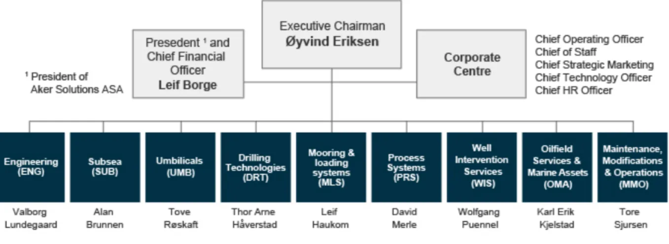
Aker Solutions. Aker Solutions brings together engineering and technologies for oil and gas
drilling, field development and production. The company employs approximately 25 000 people in more than 30 countries. They apply the knowledge and create and use technologies that deliver their customers' solutions. Aker Solutions ASA is the parent company in the group, which consists of a number of separate legal entities. Aker Solutions is used as the common brand and trademark for most of these entities. Figure 1 illustrates their organization.
Figure 1 – Organization Structure at Aker Solutions (www.akersolutions.com)
The following parts of Aker are affected by and mentioned in this report.
• Aker Engineering & Technology AS (Oslo, Fornebu)
• Aker Subsea AS (Oslo, Fornebu)
• Aker Solutions MMO AS (Bergen, Sandsli)
Some departments of Aker perform new product development, while other departments, such as Aker Solutions MMO AS in Bergen support the offshore and subsea fields through maintenance and modification tasks.
New Product Development. The PEM is Aker’s Project Execution Model, the standard
version, called PEM, is for development projects such as new installations in greenfields and brownfieldsi up to and including Major Subsea Projects. PEM is summarized in Figure 2.
Support projects. The other version of PEM is PEM for maintenance and modification,
hereafter referred to in this paper as PEMm&m. This model was developed by and used in the department for which this study was conducted. Figure 3 illustrates the primary components of this model.
Figure 2. PEM – Standard Version for new product development projects
Figure 3. PEMM&M – PEM for Maintenance and Modification Projects
As illustrated in figure 4, the ISO/IEC 15288:2008 is based on a lifecycle view of system processes, and these are divided into four major parts; Agreement Processes, Organizational Project-Enabling Processes, Project Processes, and Technical Processes. Combined, these processes span the work to take a system or product from an idea to the end of the useful life of the product. In this paper the focus will be on the technical processes as these are the ones that are the most similar to the PEM.
Methods
Gap analysis was employed to study the differences between the PEM and ISO/IEC 15288:2008. To create a balanced analysis, both models were first mapped onto the systems engineering V-model as described in the INCOSE Systems Engineering Handbook (Haskins 2010).
Gap Analysis. Gap analysis is a name given to specifying, identifying and taking action on
the gap between a situation as it exists and the desired future situation. In project management this kind of analysis could be used to find strategies to close the gap between the current situation and the vision (Karloef and Loevingsson, 2005: 160). In production, a gap might be identified between customer satisfaction as it now stands and the company’s goal for customer satisfaction; or there may be a gap between a company’s competence now and the competence it needs to handle certain strategies. A process for carrying out a gap analysis is described in the following six steps:
1. Define the area for analysis (for example internal efficiency, competence, or performance of information systems).
2. Describe the existing situation. Supplement this with metrics if necessary. 3. Describe the desired situation. Set up measurable goals if this can be done. 4. Specify how the desired situation differs from the present one.
5. Decide on measures to close the gap.
6. Follow up and where necessary carry out corrective action.
In this paper the existing process is the PEM and the desired end state proposed by the researcher is a lifecycle model tailored from the ISO/IEC 15288:2008.
The V-model. The V-model is a well-known system development model applied in many
industries for the design of products ranging from satellites to software. It drives a top-down approach to design and a bottoms-up approach to the build, integration, and test activities including validation of the as-built system against specifications (Forsberg, et. al. 2005). The Vee-model was first developed in the late 1980’s and several variants of it have been used for software development (Forsberg 1991, Schlosser 2002), automotive systems engineering (Krantz 2002), electronic system integrated hardware, software and logistic activities (Forsberg 1991). In all of these examples the main benefits of the V-model is in the systematic thinking and structured design and validation approaches it recommends in which complex problems are broken down into smaller more manageable problems at different levels of abstraction.
Analysis
The findings from the research are presented here using gap analysis to compare the similarities and differences between the PEM and the ISO/IEC 15288:2008.
Top level comparison. A quick examination of the top level processes gives an immediate first impression about the level of detail one can expect. The PEM is divided into five top level process areas as seen in figure 5. The ISO standard contains eleven technical processes, as illustrated in figure 6. This means one of two things, either PEM has too little information in its top level, or the standard is over-specified. But it is important to note that these models were developed for different purposes, so it might not be a problem that they are a bit different at first glance. These models have different uses; PEM is in use daily and is a valuable tool for the company in their daily routines, and ISO is a framework that one can visit to check if one is in compliance with what is considered as the correct way to do things. The most important feature of both models is their ability to relay the correct message to its users. Some employees, when asked about PEM have said that after a few “clicks” into it they lose sight of its structure. The point of any project execution model is to aid the users of the model to cope with everyday task in their project environment.
Figure 5 PEM Top level
Figure 6 ISO15288:2008 Top level
Because there are more technical processes, the reader begins with a more robust initial understanding of the work to be accomplished. Likewise, from the viewpoint of the systems engineer, the PEM is missing several key concepts. Requirements analysis, architecture design, integration, verification, transition, validation, maintenance and disposal are not mentioned at all in the top level. This is not a problem if these are facilitated in the deeper levels of PEM. This initial view suggests that there are several big gaps to be found in further investigation.
Mid-level comparison. If we look at the next level of the PEM it begins to resemble more
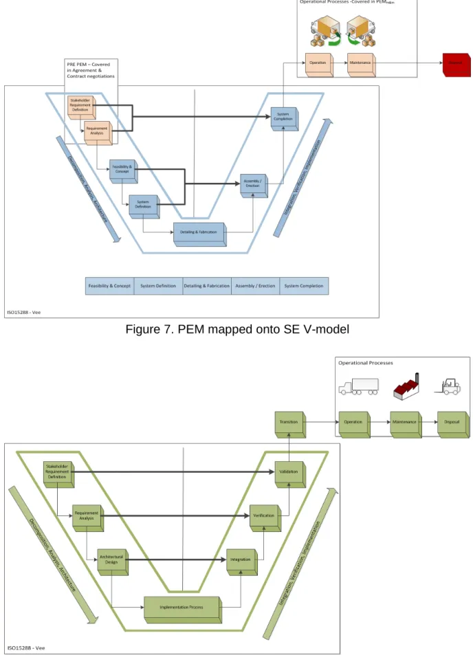
closely the top level of the standard. However, as the nomenclature between the two models is different, the researcher decided to balance the analysis by first mapping each model onto the SE V-model, before continuing any further comparisons. The task of mapping required the researcher to gain a deeper understanding of the activities associated with each process, and then to match these activities to the appropriate part of the lifecycle development model. Figures 7 and 8 illustrate the mapping for the PEM and the ISO/IEC 15288:2008, respectively.
It is known that the SE V-model stops after the customer acceptance activities, and does not cover aspects of useful life or retirement. An extension wing was added to the right side of the V-model to accommodate a full lifecycle view of the system and the associated processes provided by the standard.
Figure 7. PEM mapped onto SE V-model
This mapping in figure 8 shows that the ISO standard includes activities that cover the V-model on both sides very well. The transition process was relocated to match the normal interpretation of the development model. The placement in the standard is explained by the fact that very complex systems are often transitioned to the customer after an acceptance test but before the full capability of the product or service can be demonstrated or validated. In this mapping it is clear to see that there are gaps between the activities proposed in the PEM and the SE V-model. The blue boxes are the top level processes from PEM and the skin-color boxes are the standard boxes that are usually depicted in the SE V-model. As noted in figure 7 requirements definition and analysis is not a part of the PEM but are accomplished in negotiations with the customer as a part of the contract agreement. Thus the skin-color boxes depict activities that take place before the PEM is engaged.
Since PEM has more than one version there are some gaps/overlaps here. The skin-color boxes in the top right-hand side of the model are covered by PEMm&m. The red box named “disposal” is not covered by either version of the PEM.
Discussion
Comparison – PEM and ISO/IEC 15288:2008. This mapping shows that these models do
not agree with each other completely and there are some factors that need to be addressed. The first and most important factor would be the lack of requirement definition and analysis within PEM. When looking at PEM from a systems engineering perspective it is very unnatural not to see something about requirements up-front in the model. This shows that PEM is not a complete life-cycle model on its own. The ISO standard covers contractual activities in their own set of agreement processes. The design and subcontracting is important, but without the correct understanding of what the customer wants it is, if not impossible, very hard to get the product design and specifications correct. PEM should incorporate more items from ISO/IEC 15288:2008 into its activities level.
The implementation part of PEM seems closer to the standard, but there are also some gaps here. The biggest gap seen from the author’s point of view is the complete lack of Validation in PEM. Verification is also almost neglected in PEM. These are critical processes, and should have their own processes in PEM to show how important they are. Verification is in-house testing. (Have we met the requirements? Have we made the system correctly?) Validation is tests to show the customer that we have made the correct solution for their problem. (Is the customer smiling? Have we made the correct system?) The validation and Verification activities at Aker are based on establishing the Design Basis and the Design Review cycle. These activities are mandated by the gate review structure for project execution.
Other gaps are identified at the end of the lifecycle, where operation and maintenance activities are not covered in PEM, but rather in PEMm&m. Since PEM is more a customized company work tool than a lifecycle model, it is not unnatural that PEM does not cover all the aspects of ISO/IEC 15288:2008, but does have more detailed coverage in the implementation stages of the development model.
The lack of a disposal process in both PEM and PEMm&m is also a trigger for concern, since this is important to the lifetime calculation of the impacts of any system. Aker’s website states their strong commitment to care for natural environments, but this gap in their processes is
inconsistent with that assertion. It is vital to have a plan for what to do with our products at the end of their useful life. This would also contribute to Aker’s environment profile.
Comparison –PEM and PEMm&m. It is also important to look at what Aker describes as
PEM and PEMm&m to appraise the in-house models. Figure 2 show us how PEM is constructed and which processes and activities it contains and figure 3 show us how PEMm&m is put together. Looking at them both at the same time shows that at the top level they are very similar. The only discernible difference is the first of five processes; PEM starts out with “Feasibility and Concept” while in PEMm&m the model starts with “Scope Definition.”
In the mid-level of the models one can see more of a difference between their activities. Only the “System Definition” processes mirror each other exactly.
In the first process PEM starts with looking at the opportunity and the feasibility of the project before going into the details of the concepts. PEMm&m goes straight to concept and then further to estimation and planning.
In the third process “Detailing and fabrication” PEM has 3 steps while PEMm&m has 4 steps. In PEM, Manufacturing and Subcontracting are important activities, but in PEMm&m these are not included. PEMm&m has an additional step called work preparation.
In the fourth process “Assembly/Erection” PEM has 3 steps while PEMm&m has 2 steps. “Transport and positioning” is common to both. “Assembly” and “Mechanical Completion” are replaced in the PEMm&m by “Installation”.
In the last process “System Completion” PEM has 4 steps while PEMm&m has only 2. “Commissioning” is the common activity here. In PEM there are more details; “Offshore installation”, “Start-up” and “Take-over” are the rest of the steps in this stage compared to the PEMm&m “Close out”.
Closing the loop. Having completed the analysis, the researchers turned their attention to
what advantages, if any, Aker Solutions would derive from a true lifecycle model rather than two versions of their PEM. A lifecycle model would address the work performed by the company from project initiation to retirement of the product.
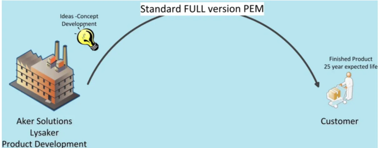
PEM is for undertaking new development projects and introducing innovation in their products, see figure 10. When a new development project comes into the Aker system it goes to the branch offices in Fornebu or Lysaker. Here they will gather information from the stakeholders and also look at and work through the requirements for the job. In this system these tasks are a part of the negotiations with the customer through the contract and agreement processes. PEM starts after the requirements are decided upon by both Aker and the customer. Concept development kicks PEM into gear and Aker follow PEM until the end of the design. PEMM&M is a specialized version made for maintenance and modification projects, illustrated in figure 11. At Aker Sandsli where this field study has been conducted, PEMM&M is used throughout all their projects, while Aker at Lysaker use the standard version PEM. According to a distinguished engineer at Aker; modification actually means two things:
1. To increase capacity without adding new technology. 2. Change a part with a new part with same type of technology.
Maintenance is the process of bringing the item to its full design performance. In this framework maintenance means only changing a part for an equal part of the same specification. Sometimes there is a change in the material used, but most times there is only a replacement part fitted. On rare occasions, and the only time Aker Sandsli uses PEM, there is a need to add something new to an existing system, like adding a new module. In this case a Modification project is set up and the standard PEM should be used.
.
Figure 10 – New development projects – PEM
Figure 11 – Todays Situation – PEM & PEMM&M
In today’s situation we can clearly see the application of each version of PEM. They work separately with maybe years of system-use in between development at Lysaker until a request arrives at a desk in Sandsli for either Maintenance or Modification. According to Luca
A. Piciaccia, Chief Engineer Program Manager at Aker Solutions, in the case of pure maintenance involving no performance envelope expansion, there is little to no
communication between product developers and the maintenance departments when a component comes back into the Aker system for the second or maybe third time. This is possible since all design documents are in the main company repository, SAP, and the final status of the equipment shall be no different from what was specified and described in the original project. It is a case of constructing an already fully approved component.
This is an issue which needs to be visualized and lifted into the correct forums for further discussion. The “budget” and “constraints” depicted in figure 11 are not the same. The first is the budget and constraints for the development and the latter one is the new constraints and budget for the maintenance or modification project. This is important as it illustrates the nature of the changes necessary to evolve the PEM a full on lifecycle model.
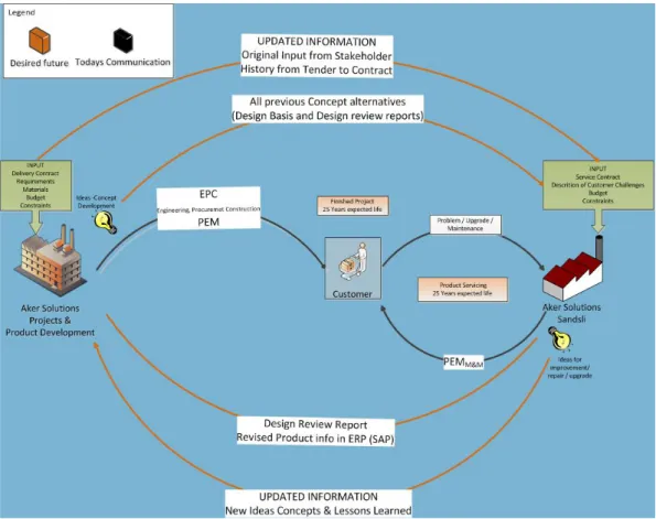
Figure 12 depicts the desired future situation for PEM where the goal is to make PEM into a lifecycle model that encompasses some new features to facilitate the change from an execution model into a lifecycle model. All the new features in this model are based on communication, mostly between the different branches of Aker. There are some key parameters here: The development process will not have to change much, but as soon as a product enters into the Aker system for maintenance or modification some changes will be needed.
1. All information about the development of this product should be available for the maintenance and modification crew at Sandsli. The full project documentation from tender to delivery is available, but it is not structured in a way that facilitates the retrieval of the information necessary for the M&M department. Thus updated information and lessons learned should be made available in a more structured way, together with data from the concept definition process, to avoid trying the same solution one more time.
2. When a new solution has been proposed by Aker at Sandsli and the product return to active duty, the information about the updates and changes that have been made should be made available for the development department within Aker. There are lessons to learn here on how to prolong the useful life of a product. A full design review report of the new solution shall be filed to maintain the quality records, if the change involved fit, form, function or manufacturing process a new part number and technical documentation package shall be assigned to the improved item. A new part number is also necessary when the improvements affect backward compatibility of the item.
3. The main documentation of the product must be updated with the changes made in the maintenance or modification.
Figure 12 – Desired Future Situation
Conclusion
The research done and the deviations documented by this report suggest that Aker would benefit from and increase their success of projects by introducing missing elements of the ISO/IEC 15288:2008 standard processes into their project execution strategy.
PEM has a visible focus towards implementation elements of the lifecycle. This is evident in figure 7 where PEM is mapped onto the systems engineering V-model. The boxes depicting PEM starts at the lower part of the left leg of the Vee and stop at the top of the right leg. In the discussion of System Development Life Cycle model (SDLC) and Full Life Cycle Model it is clear that PEM in today’s version is a development life cycle model and to become more like a full life cycle model PEM needs to be changed according to figure 12. It is the authors understanding that gathering all project execution activities into PEM and make it into a full life cycle model would make PEM a more important and more useful tool within the company.
Further reflection on the use of the standard (and the accompanying INCOSE Systems Engineering Handbook) suggests that these are well constructed and useful products that assist in the analysis of current situations, and the development of tailored approaches for future improvements.
References
Aker Solutions ASA- Web Page: http://www.akersolutions.com/ - Visited 16.10.2012.
Forsberg, Cotterman & Mooz. 2005, Visualizing Project Management. 3rd Edition. New Jersey, NY (US): Wiley.
Forsberg, K., Mooz, H., 1991 The Relationship of System Engineering to the Project Cycle, Proceedings of NCOSE & ASEM
Haskins, C., ed. 2010. Systems Engineering Handbook: A Guide for System Life Cycle Processes and Activities. Version 3.2. Revised by M. Krueger, D. Walden, and R. D. Hamelin. San Diego, CA (US): INCOSE.
IEEE, ISO/IEC 15288, 2008, Systems and software engineering - System life cycle processes, Karloef, B; Loevingsson, F. 2005 A to Z of Management Concepts and Models. London, GBR:
Thorogood Publishing.
Kranz, W., 2002. An Integrated System Development Process Including Hardware and Logistics based on a Standard Software Process Model, paper presented at the RTO IST Symposium on Technology for Evolutionary Software Development, Bonn, Germany.
Schlosser, J., 2002 Requirements for Automotive Systems Engineering Tools, Proceedings of the IEEE International Conference on Computer Design: VLSI in Computers and Processors.
i Greenfield: new installation on areas previously not developed; Brownfield: new or additional installation on
areas already developed or extension towards an adjacent field, where common infrastructures might be shared. These terms are borrowed from land use concepts.