DATACAB: EXPERT SYSTEM FOR
AUTOMATIC DESIGN OF CABLE NETWORKS
Carlos León
1, Robert Denda
2,Iñigo Monedero
1,Samuel Muñoz
2,José M.Elena
1, Joaquín Luque
11
Escuela Técnica Superior de Ingeniería Informática.
Departamento de Tecnología Electrónica
Avda, Reina Mercedes s/n
41012 Seville (Spain)
2
Enditel Endesa
R&D Department
World Trade Center
Isla de la Cartuja s/n
41092 Seville (Spain)
Abstract
This paper describes a current project, called Datacab, developed by the Electronic Technology Department of the University of Seville and Enditel Endesa. The aim of this work is to develop an expert system for automatic routing of a cable telecommunication network as well as the civil design. Datacab obtains an optimal design based on a GIS (Geographic Information System) data and a design rules database. Some of the advantages of the proposed expert system approach are the possibility to add new rules or modify present rules easily if design criteria changes or to train new stuff.
Keywords: Expert system, HFC network, GIS, Kruskal’s algorithm.
1. - Introduction
An expert system is a computer software program that emulates or clones the reasoning of a human expert in a problem domain. A problem domain is a special subject area in which the expert can solve problems in an easy way. The human expert possesses the high level of competency necessary to solve a difficult problem [1]. Expert system technology has been successfully applied to telecommunication networks [2][3][4]. The routing task has sometimes been approached using soft computing techniques too, as the A* algorithm [5]. Datacab use GIS's city data to obtain a design of a HFC (Hybrid Fiber Coax) network consisting of an optical fiber network, a coax network, and a telephony network, using the expert design rules obtained throughout a knowledge acquisition process. Datacab will be applied to various cable communication networks with an average of more than 200.000 users each.
The cable network structure to be designed supports CATV and telephonic services. The fiber optic network is structured in a head-end connected to a primary network containing a number of main nodes that services between 30.000 to 90.000 homes each one. These main nodes are connected to a network of several secondary nodes (secondary networks), each of which serves around 10.000 homes and contains a RTC (Remote Telephony Center) too. The tertiary networks (distribution network) come from every secondary node and services to 2.000 homes. Every tertiary network ends in ONTs (Optical Network Termination), which are connected to a Coax Network. This Coax Network finally distributes the signal to subscribers.
The Telephony Network comes from each RTC and has three levels. The first level connects each RTC to a ONT, the second level reaches each block, and finally, the third level is connected to the subscribers’ homes.
Some of the advantages of the proposed expert system approach are the possibility of adding new rules and to modify present rules easily if the design criterion changes. Design rules can be stored in a database in order to improve accessibility; finally the developed system can be used to train new staff. Datacab prototype is being programmed using the shell of Art*Enterprise tool.
2. – DATACAB development process
2.1.- Objectives
Our objective consists of the development of an expert system for designing HFC cable network (fiber, RF, civil elements and telephony).
We centered our primary objective in the design of the RF (coax) network because the civil design would be based
on it. We postponed the fiber network design because of economical motives and its shorter design time.
2.2. - Knowledge Acquisition
The first step in building an expert system is the knowledge acquisition. It involved eliciting, analyzing, and interpreting the knowledge about the current network design. Several techniques for extracting expert knowledge have been described in the literature [6]. We selected a structured interview approach with the expert operators as the main acquisition technique. A structured interview is a conversation between the experts and the knowledge engineers. The difference between a structured interview and a normal meeting is that the knowledge engineer must decide the questions and objectives to discuss before the meeting. A specialized technician was commended for carrying out the expert work. Along 5 sessions from 1 to 2 hours were necessary to build our first knowledge base.
2.3.- Knowledge Representation
Once knowledge had been acquired, the next step was its representation. A class diagram and a rule-based system would be built for it. The mapping elements as well as their location and the re-design information (i.e. possible access to accommodations, previous channel locations, non-permitted façades, ...etc) are obtained from the GIS application. So, the information from GIS and our RF elements are converted to instances of Datacab’s classes. 2.3.1.- Class diagram
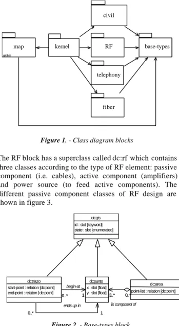
The class diagram of Datacab was designed with the help of the Rational Rose tool using an UML approach [7], and it is composed of 7 blocks, which were linked in the way shown in figure 1. It would include the GIS elements (streets, buildings, ...etc), re-designing information (i.e. buildings accesses), RF elements (wires, amplifiers, ...etc) and civil elements (caskets, channels, ...etc) in addition to superclasses of all previously mentioned elements (point-class, RF-(point-class, ...etc). These superclasses were created to generalize some common properties of our objects such as distances in linear elements and signal losses in RF passive elements.
The kernel block was made up by the knowledge classes as algorithm-class.
All the Datacab’s classes derived from one superclass called dc:GIS from the base-types block (see figure 2). This class embraces the main shapes from GIS elements: point, line and area. On the other hand, in the map block are the classes relative to city elements: buildings, blocks, streets, roads, parks, ...etc.
Figure 1. - Class diagram blocks
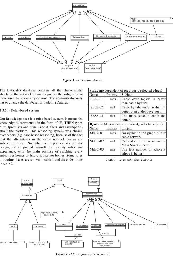
The RF block has a superclass called dc:rf which contains three classes according to the type of RF element: passive component (i.e. cables), active component (amplifiers) and power source (to feed active components). The different passive component classes of RF design are shown in figure 3.
Figure 2. - Base-types block
In this example (figure 3), the advantages of the inheritance can be seen. So, inherited classes from dc:passive get the characteristics from RF elements and graphic elements.
Finally, the design of civil component classes are made up by a main class called dc:civil. In the same way as the rest of the superclasses, dc:civil has two child classes depending on characteristics, distinguishing sections and points. So, the first class also inherits from dc:line whereas the second one from dc:point. Besides, the telephony and fiber blocks were created thinking on Datacab future versions. The whole class diagram of civil components is shown in figure 4.
Datacab will instantiate one copy of the different child classes of RF diagram and civil diagram and the attributes on technical characteristics are filled in according to their constructor via database accesses.
map global kernel RF telephony fiber civil base-types dc:gis id : slot [keyword] state : slot [enumerated]
1 0..*
1 0..*
dc:trazo start-point : relation [dc:point]
0..*
dc:area point-list : relation [dc:point] 3..* dc:punto x : slot [float] 1 0..* begin-at 1 0..* ends up in 0..* 3..* iis composed of end-point : relation [dc:point] y : slot [float]
The Datacab’s database contains all the characteristic sheets of the network elements just as the subgroups of these used for every city or zone. The administrator only has to change the database for updating Datacab.
2.3.2. - Rules-based system
Our knowledge base is a rules-based system. It means the knowledge is represented in the form of IF...THEN types rules (premises and conclusions), facts and assumptions about the problem. This reasoning system was chosen over others (e.g. case-based reasoning) because of the fact that the alternatives in the cable network design are subject to rules. So, when an expert carries out the design, he is guided himself by priority rules and experience, with the main premise of reaching every subscriber homes or future subscriber homes. Some rules in routing phases are shown in table 1 and the code of one in table 2.
Static (no dependent of previously selected edges) Name Priority Subject
SESS-01 max Cable over façade is better than cable by tube.
SESS-02 mid Cable by tube under asphalt is better than under pavement. SESS-03 min The more save in cable the
better.
Dynamic (dependent of previously selected edges) Name Priority Subject
SEDC-01 max No cycles in the graph of our cable network
SEDC-02 mid Cable doesn’t cross avenue or Main Street is better.
SEDC-03 min The less number of adjacent edges is better
Table 1. - Some rules from Datacab
dc:channel dc:line (from base-type) dc:point (from base-type) dc:civil #type (1, 2, 3, 4, 5, 6, 7, s1, s2, s3, s4) #type (not2000, 80x90, 60x60, 40x40)
#type (not, source, amplifier, single-family-amplifier, base, network) dc:air
#tipo (front, roof, inside)
dc:civil-section dc:civil-element dc:sweep-tee dc:front-access-pipe dc:basament-wardrobe dc:wardrobe Is-held-by dc:sarcophagus dc:chest has one
Only if chest puts up a amplifier
Figure 4. - Classes from civil components
dc:point (from base-type)
dc:passive
dc:directional-adapter dc:splitter
dc:tap Dc: current-blocking dc:hire
dc:line (from base-type)
#type
(QR-540, RG-11, RG-6, RG-59)
dc:ecualizer Dc:terminal-charge
(define-rule SESS-01 (declare (salience 900))
(object ?algorithm (instance-of algoritmo500-1) (phase static-cost) (CS ?node-list) (RS ?non-node-list)) (object ?via1 (instance-of dc:street)) (object ?via2 (instance-of dc:non-façade)) (test (not (equal ?street1 ?street2))) (test (not (member$ ?street1 ?node-list))) (test (not (member$ ?street1 ?non-node-list))) (test (superimposed ?street1 ?street2)) =>
(add-attribute-value ?algorithm CS ?street1))
Table 2. –Code of SESS-01 rule
3.- Datacab’s Implementation
3.1. - Phases of the execution
The different phases of the Datacab’s execution are shown in the figure 5 and for the code task of these phases we used a powerful tool for expert systems called Art*Enterprise
The first and the last process of the execution diagram (GIS Interpreter) are simple thanks to the great ease of the GIS tool to export data to a desired format. So that, the interpreter module would generate a file with the GIS information facilitating the conversion process.
The attributes of GIS elements are specified in our class diagram and the created objects in the second step will be instances of these classes.
3.2. - Search algorithm
The kernel block (see figure 1) has embedded the dc:kernel superclass and dc:algorithm class. These classes, which made up the knowledge base, would take care of firing rules in every phase of the algorithm. Besides, in dc:algorithm it would be stored the results. The kernel algorithm, currently under development, will be made up of phases each one of which will fire a group of rules. The idea of the first algorithm design consists of a cable network routing first and later, once carried it out, a location of the RF and civil elements. If it were not possible to place the elements with one cable network routing, it would be carried out another routing.
The first stage of the search algorithm would be based on the Kruskal’s algorithm [8], which is an ancient minimum expansion tree search algorithm. These algorithms have a connected graph as input and generate a tree, which covers the whole graph with lowest cost. In particular, Kruskal’s algorithm selects the lowest cost edge in each one of the iterations, as long as, this doesn’t generate cycles.
Figure 5.- Execution diagram of Datacab
The difference between Kruskal’s algorithm and our algorithm would be in the dynamic characteristic of the latter one. While the edge cost in Kruskal’s algorithm doesn’t depend on the previously selected edges, in our algorithm the cost would be able to vary. The different phases in algorithm of Datacab are shown in figure 6.
Figure 6.- Datacab algorithm phases GIS Interpreter GIS Information Datacab Information Creation of object instances Database Queries Attributes filling Algorithm RF and Civil Elements GIS Translator Datacab Solution GIS Solution initialization sorts-edges-by-static-cost selects-edges-by-dynamic-cost places-RF-civil-elements resorts-edges-by-static-cost calls GIS Translator If it’s not possible If it’s possible
In addition, we are looking into another alternative for the algorithm. It consists in placing RF and civil elements at the same time the cable network is designed. This solution is more in accordance with the working mode of a design expert but it has been postponed because of its more complicated implementation.
The features from the RF elements will be passed over through a database access depending on the city or zone. Once the kernel processes and gets a solution, this solution will become information in the GIS database.
4. – Conclusions
We have developed an expert system for the automatic design of cable networks and placing of civil elements. Up to now, the initialization phase and the two phases of routing tasks have been implemented, as well as, the code of the class diagrams. We’ve designed the stage of the project that will place the RF and civil elements.
Currently, we are preparing a test method (validation process). Once finalized these phases, an expert will verify the correct designs of networks carried out by Datacab (verification process).
5. - References
[1] E.M. Awad. “Building Expert Systems”. West Publishing Company, 1996.
[2] C. León, M. Mejías, J. Luque y F. Gonzalo. “Expert system for the integrated management of a power utility’s communication system”. IEEE Transactions on Power Delivery, vol. 14, nº 4, pp, 1208-1212, Oct. 1999.
[3] Jay Liebowitz ed. “The handbook of Applied Expert Systems”. CRC Press, 1998.
[4] I. Vlahuvas et al. “ ExpertNet: An Intelligent Multiagent System for WAN Management”. IEEE Intelligent Systems, vol. 17 , nº4 , pp, 62-72, 2002. [5] S. Russell y P. Norvig. “Inteligencia Artificial. Un enfoque moderno”. Prentice-Hall Hispanoamericana, 1999.
[6] K.L. McGraw and K. Harbison-Briggs. “Knowledge acquisition: Principles and guidelines”. Prentice-Hall, Englewood Cliffs, N.J.
[7] G. Booch, J. Rumbaugh and I.Jacobson. “UML. El Lenguaje Unificado de Modelado”, Addison Wesley, 1999.
[8] R. Sedgewick: “Algoritmos en C++”. Addison Wesley Iberoamerica, 1995.