Performance Analysis of a Nonlinear Coupled-Tank
System Using PI Controller
Mustafa Saad
Department of Control Engineering, College of Electronic Technology, Bani-walid, Libya
Copyright©2017 by authors, all rights reserved. Authors agree that this article remains permanently open access under the terms of the Creative Commons Attribution License 4.0 International License
Abstract
In the process industry many of the control applications deal with liquid level, flow, temperature and pressure processes. This paper presents the approach of modeling and controller design of liquid level control system for a nonlinear Coupled-Tank System. First of all, the mathematical equations for the nonlinear system are explored. And then, proportional plus integral (PI) controller is designed to control the level of the second tank for the nonlinear model, through variable manipulation of water pump in the first tank. The simulation study is done using MATLAB and the performance analysis in time domain of the controller is identified. In addition, ITAE criterion is used to evaluate the controller performance. Finally, the simulation results indicate that the controller work very well and the proposed controller has the ability to reject the effect of the disturbance.Keywords
Coupled-Tank System, Nonlinear Model, PI Controller, ITAE1. Introduction
The industrial application of liquid level control is huge especially in chemical industrial processes. Usually, level control exists in some of the control loops of a process control system. An evaporator system is one example in which a liquid level control system is a part of the control loop [1].
Nowadays, the process industries such as petro-chemical industries, paper making and water treatment industries require liquids to be pumped, stored in tanks, and re-pumped to another tank. The control of liquid in tanks and flow between tanks is a basic problem in the process industries. In the design of control system, a complicated mathematical model is applied that has been obtained from fundamental physics and chemistry.
Many other industrial applications are concerned with
level control, may it be a single loop level control or sometimes multi-loop level control. In some cases, level controls that are available in the industries are for interacting tanks. Hence, level control is one of the control systems variables which are very important in process industries [2].
PI controller is a widely used to control most of industries like automation and industrial processes because it has simple structure and easy to implement and use for a non linear process. In addition, its stand only for their certain specifications like rise time, peak time, overshoot and steady state error.
The PI controller is commonly used in practice due to steady state regulation and to use manual controller for large changes. PI controller is widely used in industrial applications of liquid level control and allows for the functionality of liquid level control systems with moderate performance specifications.
There are many of control strategies and methods in controlling the liquid level in the coupled-tank system such as hybrid control system consisting of a PID controller and a time optimal controller [3], Level Control of Cascade Coupled Flotation Tanks [4], Improved coupled tank liquid levels system based on swarm adaptive tuning of hybrid proportional-integral neural network controller[5], Sliding Mode Control of Coupled Tanks [6], Tuning of a Neuro-Fuzzy Controller by Genetic Algorithms with an Application to a Coupled-Tank Liquid-Level Control System. Engineering Applications of Artificial Intelligence [7], Modeling of a Coupled Industrial Tank System with ANFIS [8], Direct Model Reference Adaptive Control of Coupled Tank Liquid Level Control System [9], and robust control of a multivariable system[10].
56 Performance Analysis of a Nonlinear Coupled-Tank System Using PI Controller
2. Mathematical Model of Coupled-
Tank System
It is very important to understand the mathematics of how the coupled tank system behaves. System modeling involves developing a mathematical model by applying the fundamental physical laws of science and engineering to the system. Nonlinear dynamic model with time-varying parameters are obtained.
The schematic coupled-tank system apparatus, as shown in Figure 1, consists of two identical tanks coupled by an orifice. The input is supplied by a variable speed pump which supplies water to the first tank. The orifice allows the water to flow into the second tank and hence out to a reservoir. To maintain or control the water level in the second tank H2 at some desired value, the input flow rate
in the first tank Qi1 need to be adjusted by adjusting the
[image:2.595.67.293.319.462.2]pump voltage. In process control terms, the input flow rate is known as the manipulated variable.
Figure 1. Schematic diagram of coupled tank apparatus [1]
A simple nonlinear mathematical model is derived with a help of this diagram. Let H1 and H2 be the liquid level
in each tank, measured with respect to the corresponding outlet, considering a simple mass balance, the rate of change of liquid into the tank. Thus for each of tank 1 and tank 2, the dynamic equation is developed as follow.
𝐴𝐴1𝑑𝑑𝑑𝑑𝑑𝑑𝑑𝑑1=𝑄𝑄𝑖𝑖1− 𝛼𝛼1�𝐻𝐻1− 𝛼𝛼3�𝐻𝐻1− 𝐻𝐻2 (1)
𝐴𝐴2𝑑𝑑𝑑𝑑𝑑𝑑𝑑𝑑2=𝑄𝑄𝑖𝑖2− 𝛼𝛼2�𝐻𝐻2+ 𝛼𝛼3�𝐻𝐻1− 𝐻𝐻2 (2)
Where
H1, H2 = height of liquid in tank1 and tank2 respectively. A1, A2 = cross-sectional area of tank1 and tank2
respectively.
Qi1, Qi2 = pump flow rate into tank1 and tank2
respectively.
α1, α2, and α3 are proportionality constant which
depends on the coefficients of discharge, the cross-sectional area of each orifice and the gravitational constant.
For the coupled tanks apparatus, the fluid flow, Qi1, into
Tank 1, cannot be negative because the pump can only pump water into the tank. Therefore, the constraint on the inflow rate is given by
𝑄𝑄𝑖𝑖1> 0 (3)
Given the general model in
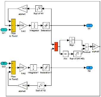
𝐻𝐻1̇ =𝐴𝐴11�𝑄𝑄𝑖𝑖1− 𝛼𝛼3�𝐻𝐻1− 𝐻𝐻2𝑠𝑠𝑠𝑠𝑠𝑠𝑠𝑠(𝐻𝐻1− 𝐻𝐻2)− 𝛼𝛼1�𝐻𝐻1�
(4) 𝐻𝐻2̇ =𝐴𝐴12�𝑄𝑄𝑖𝑖2+ 𝛼𝛼3�𝐻𝐻1− 𝐻𝐻2𝑠𝑠𝑠𝑠𝑠𝑠𝑠𝑠(𝐻𝐻1− 𝐻𝐻2)− 𝛼𝛼2�𝐻𝐻2�
Figure 2. Nonlinear model of coupled tank system simulation
Figure 3. The mask of nonlinear model simulation
The valve/pump actuator can be also modeled as it is, in the fast, an important control element in the plant. The following differential equation describes the valve/pump actuator is dynamics [8]. The valve/pump actuator has been modeled in simulation for the nonlinear system and masked under JPEG Image as shown in Figure 4 and Figure 5 respectively.
𝑇𝑇𝑐𝑐𝑑𝑑𝑞𝑞𝑑𝑑𝑑𝑑𝑖𝑖(t)+𝑞𝑞𝑖𝑖(𝑡𝑡) =𝑄𝑄𝑐𝑐(𝑡𝑡) (6)
Where
Tc is the time constant of the value/pump actuator. qi(t) is the time –varying input flow rate.
[image:3.595.306.535.438.739.2]Qc(t) is the computed or the commanded flow rate.
Figure 4. Valve/pump actuator simulation.
58 Performance Analysis of a Nonlinear Coupled-Tank System Using PI Controller
Table 1. Parameters of Coupled Tank System [2]
Name Expression Value
Cross section area of the couple
tank reservoir A1& A2 32 𝑐𝑐𝑐𝑐2
Proportionality constant that depends on discharge coefficient,
orifice cross Sectional area and gravitational constant Subscripttank it refers i denotes Which
𝛼𝛼1 𝛼𝛼2 𝛼𝛼3
14.3
cm2/3/sec cm14.3 2/3/sec cm2/320 /sec
Pump motor time constant Tc 1 𝑠𝑠𝑠𝑠𝑐𝑐
Maximum allowable volumetric
flow rate pumped by motor 𝑄𝑄𝑠𝑠𝑚𝑚𝑚𝑚𝑚𝑚 300 𝑐𝑐𝑐𝑐3/𝑠𝑠𝑠𝑠𝑐𝑐
The parameters used for simulation as shown in Table 1, was tested experimentally in previous work.
3. Controller Design for Coupled-Tank
System
Proportional-Integral controller is as one of feedback controller whose output, a control signal which applied to the actuator to affect the manipulated variable which in turn gives a change in the controlled variable. The input is generally based on the error between some user defined set-point and some measured process variable. Each element of the PI controller refers to a particular action taken on the error.
𝐺𝐺(𝑠𝑠) =𝑈𝑈(𝑠𝑠)𝐸𝐸(𝑠𝑠)=𝐾𝐾𝑝𝑝+𝐾𝐾𝑠𝑠𝑖𝑖
Proportional term: the proportional term can be obtained by multiplying the error signal by a gain, Kp. This is an
adjustable amplifier. In many systems Kp is responsible
for process stability, if Kp is too low may makes the
controlled variable to drift away. Too highKpmay makes
the controlled variable to oscillate.
Integral term: the integral term can be obtained by multiplying the integral of the error signal by a gainKi. In
many systems Ki is responsible for driving error to zero,
but set Ki too high is to invite oscillation or instability or
integrator windup or actuator saturation.
Table 2. Effect of increasing the controller parameters Controller
parameter Rise time Overshoot Settling time Steady state error Kp Decrease increase Small change decrease Ki Decrease increase increase eliminate
Trial and error is good choice to tune the PI controller parameters for the nonlinear model, this method require well understanding about the effect of controller parameters on the system performance. Table 2 shows the effect of increasing the controller parameters on the system response.
Steady-state error in a control system is a measure of system performance when the transient phase of response is over. It indicates the accuracy with which the system output can track a given input where, it can be defined as the difference between the input and output. One objective of the controller design is to keep the error below a certain acceptable limit, if it cannot be completely eliminated.
The integral time absolute error (ITAE) criterion is known as performance index which can be calculated or measured and used to evaluate the system's performance. A quantitative measure of the performance of the system is necessary for the design of optimum systems. A performance index must be chosen when the aim is to improve the design of control system. A system is considered an optimum control system when the system parameters are adjusted so that the index reaches an extremum, commonly a minimum value. To be useful, a performance index must be number that is always positive or zero. ITAE is used to emphasize errors occurring later in the response. It’s designated the integral time multiplied by absolute error [11].
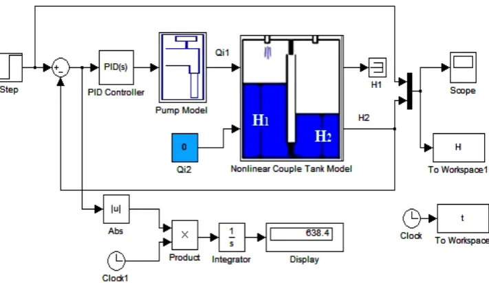
[image:4.595.55.293.596.648.2]Figure 6. Simulink diagram to simulate PI controlled coupled– tank.
4. Simulation Results and Discussions
This paper aims to control the level of the second tank H2 for the nonlinear model by adjusting the manipulatedvariable Qi1. The desired performance specifications for
this system are the desired set point or the desired water level in the second tank is 9 cm, a good transient response should be observed and zero steady state error should be obtained. Figure 7 shows the simulation result of PI controller for different values of Kp and Ki. That has been
[image:5.595.122.478.82.288.2]tuned using trial and error method.
Figure 7. Output response of couple tank system using PI controller
Depends on Table 2 the PI controller parameters is tuned using trial and error method and it can be seen that, the response at Kp= 40 and Ki= 5 has a fluctuation in the
transient response of the system which is not acceptable for this system. High overshoot practically may causes overflow from the tank. Furthermore the settling time is large due to the high integral gain. The final value of the output response reaches the steady state value at the desired
[image:5.595.303.544.415.526.2]point hence zero steady state error is obtained. To overcome the high overshoot in the output response and stabilizing the system even more, the proportional gain has been decreased. Also, the integral gain is decreased to reduce the settling time. Table 3 shows the performance specification for different trial and error tuning of the PI controller gains.
Table 3. Performance Specifications using PI Controller Performance
Specifications 𝐾𝐾𝐾𝐾𝑝𝑝𝑖𝑖= 40= 5
𝐾𝐾𝑝𝑝= 30
𝐾𝐾𝑖𝑖= 1.5
Kp= 15.6 Ki= 1.3
Overshoot % 59.55% 15.5% 5.77%
Peak Time (sec.) 9.57 9.1 13.86
Raise Time (sec.) 3.46 4.14 7.06
Settling Time (sec.) 56.47 43.90 32.88
Steady State Error 0 0 0
Dead Time (sec.) 3.53 4.6 6.52
After few trial and error steps, the best response in blue solid line is captured at Kp= 15.6 and Ki= 1.3, the
overshoot is reduced to 5.77% compared with the first obtained response which illustrated by black dash dotted line, that has an overshoot 56.47%. On other hand, the response became slower and the dead time increased due to reducing the proportional gain. The output response reaches ±2% of its final value at 32.88 second which means the settling time is reduced by decreasing the integral gain to 1.3.
The ITAE performance indices is used in this paper to measure the system performance, Table 4 illustrates the performance of the controller for different tuning of PI controller using ITAE.
Table 4. Performance ITAE Performance Specifications Performance
Specifications 𝐾𝐾𝐾𝐾𝑝𝑝𝑖𝑖= 40= 5 𝐾𝐾𝐾𝐾𝑝𝑝𝑖𝑖= 1.5= 30 𝐾𝐾𝐾𝐾𝑝𝑝𝑖𝑖= 15.6= 1.3
ITAE 1782 1031 638.4
0 20 40 60 80 100 120
2 4 6 8 10 12 14
Time (sec)
W
at
er
lev
el
tank
2 (
cm
)
[image:5.595.64.280.452.637.2]60 Performance Analysis of a Nonlinear Coupled-Tank System Using PI Controller
From Table 4, the ITAE has been decreased as the controller gains are decreased. At the gains Kp= 15.6 and Ki= 1.3 the controller gave the best
performance.
The simulation is carried with loading the disturbance to show the ability of the controller for the disturbance rejection that acting on the system. The Simulink diagram of the controlled nonlinear model and the step response of the system under effect of the disturbance are shown in
Figure 8 and Figure 9 respectively.
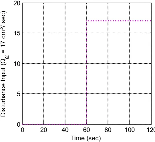
The second motor pump in the second tank is switched ON and supplies with flow rate of magnitude 17 cm3/sec.
[image:6.595.129.465.197.387.2]This disturbance has been applied to the system after 60 second from the system running. The disturbance input signal is shown in Figure 9 and the output response of couple tank system using PI controller under effect of disturbance is shown in Figure 10.
[image:6.595.163.431.419.664.2]Figure 8. Simulink diagram to simulate PI controlled coupled– tank under effect of disturbance.
Figure 9. Disturbance input signal
0
20
40
60
80
100
120
0
5
10
15
20
Time (sec)
D
is
tur
banc
e I
nput
(Q
i2=
17 c
m
3
/ s
ec
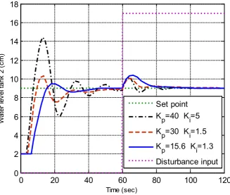
Figure 10. Output response of couple tank system using PI controller under effect of disturbance
It can be seen from these responses in Figure 10, that the output converges to its desired value in all three cases, which means that, the disturbance has been rejected by the controller.
5. Conclusions
The control of the coupled-tanks nonlinear model is addressed in this paper. A control system of the nonlinear model is successfully designed and developed such that the water level height tank in the second tank can be controlled at any desired level. Ziegler-Nichols tuning method is limited for linear model so that, the trial and error is used in this paper to tune the PI controller parameters. The simulation result demonstrated that, the PI controller canceled the error of the system, this is due to the integral term of the controller and the transient response has been slightly improved. The performance of the controlled system is considered in presence of an external disturbance and the simulation results illustrated that the proposed PI controller works very well. Hence, the robustness of the controller to reject the disturbance is investigated.
REFERENCES
[1] M. Saad, A. Albagul, and Y. Abueejela, “Performance Comparison between PI and MRAC for Coupled-Tank System,” JOACE, 2 (3). 316-321, September 2014.
[2] A. H. Yousif, S. Buyamin, and N. Abdul Wahab, “Integral Time Absolute Error Minimization for PI Controller on Coupled- Tank Liquid Level Control System Based on Stochastic Search Techniques,” Journal Teknologi (Sains & Kej.) Keluaran Khas. 381– 402, Jan. 2011.
[3] J, Malmborg, and J. Eker, “Hybrid Control of A Double Tank System in Control Applications,” Proceedings of the IEEE International Conference. 1997.
[4] B. Stenlund, and A. Medvedev, “Level Control of Cascade Coupled Flotation Tanks,” Control Engineering Practice, 443- 448, 2002.
[5] M. S. Ramli, R. M. T. R. Ismail, M. A. Ahmad, S. M. Nawi, and M. A. M. Hussin, “Improved coupled tank liquid levels system based on swarm adaptive tuning of hybrid proportional-integral neural network controller,” American J. of Engineering and Applied Sciences, 669-675, 2009. [6] N. B. Almutairi, and M. Zribi, “Sliding Mode Control of
Coupled Tanks,” Elsevier J. Mechatronics, 427-441, 2006. [7] T. L. Seng, M. Khalid, and R. Yusof, “Tuning of a
Neuro-Fuzzy Controller by Genetic Algorithms with an Application to a Coupled-Tank Liquid-Level Control System. Engineering Applications of Artificial Intelligence,” In press, 517-529, 1998.
[8] S. N. Engin, J. Kuvulmaz, and V. E. Ömürlü, “Modeling of a Coupled Industrial Tank System with ANFIS,” in MICAI Advances in Artificial Intelligence, 804-812, 2004.
[9] M. N. b Mahyuddin, Direct Model Reference Adaptive Control of Coupled Tank Liquid Level Control System, Ms. Eng. Thesis, Dept. Mechatronics and Automatic Control, Universiti Teknologi Malaysia, October 2005.
0
20
40
60
80
100
120
0
2
4
6
8
10
12
14
16
18
Time (sec)
W
at
er
lev
el
tank
2 (
cm
)
Set point
K
p=40 K
i=5
K
p=30 K
i=1.5
K
p=15.6 K
i=1.3
[image:7.595.131.459.89.366.2]62 Performance Analysis of a Nonlinear Coupled-Tank System Using PI Controller
[10]Mircea Dulau, Stelian-Emilian Oltean and Adrian- Vasile Duka, “Robust Control of a Multivariable System,” Elsevier, Procedia Eng. (181), 626-633, 2017.
![Figure 1. Schematic diagram of coupled tank apparatus [1]](https://thumb-us.123doks.com/thumbv2/123dok_us/8752079.892123/2.595.67.293.319.462/figure-schematic-diagram-coupled-tank-apparatus.webp)
![Table 1. Parameters of Coupled Tank System [2]](https://thumb-us.123doks.com/thumbv2/123dok_us/8752079.892123/4.595.55.293.596.648/table-parameters-coupled-tank.webp)