Robust Adaptive Backstepping Controller for Altitude
Control of a Small Scale Helicopter by Considering the
Ground Effect Compensation
Tushar K. Roy
Department of ETE, RUET, Bangladesh *Corresponding author: [email protected]
Copyright © 2013 Horizon Research Publishing All rights reserved.
Abstrac
t In this paper, I focus on the design and
implementation of a controller for a two degree-of-freedom system. A nonlinear robust adaptive control technique is proposed to control the altitude of a small-scale helicopter for hovering as well as vertically take-off/landing near the ground surface in the presence of strong horizontal wind gusts. In order to stabilize the vertical dynamics of the small-scale helicopter, a recursive (backstepping) design procedure is used to design the robust adaptive controller based on Lyapunov approach. Simulation results demonstrate that the proposed robust adaptive backstepping controller is capable of controlling the altitude for hovering flight of a small-scale helicopter near ground surface in the presence of strong horizontal wind gusts.Keywords
Robust Adaptive Backstepping Control, Ground Effect, Lyapunov Function, UAH1. Introduction
Among the variety of Unmanned Air Vehicles (UAVs), unmanned autonomous helicopters constitute one of the most versatile and agile platforms. A helicopter can operate in different flight modes, such as vertical take-off/landing, hovering, longitudinal/lateral flight, and bank to turn which gives them the advantage of effective observation from various positions. Among these abilities hovering and vertical take-off is necessarily needed. Unmanned autonomous helicopter control system should make these performances achieved by improving the tracking performance and disturbance rejection capability in different weather conditions. Comparing with the fixed wing aircraft, that of helicopter altitude is much lower and close to the ground; so ground effect is the important topic [1]. Ground effect is most significant in hover, and below the heights of the order of a rotor radius. Ground effect usually supports the additional lift of the helicopter, so it should be considered in
adaptive control, while [8] uses neural network based control, to deal with both unmodeled dynamics and aerodynamic disturbance from the environment. Even though the helicopter altitude control problem is successfully resolved in [9, 11], but the effects of wind disturbances are not taken into account within the system model. For altitude control near the ground surface, a sliding mode controller is proposed in [12], in which a constant wind disturbance is used.
It should be emphasized that very few research works in the literature, are taking into account the ground effect and external wind gusts in the altitude control of a small helicopter near ground surface. In the previous version of this paper [13], the authors designed a robust backstepping controller for altitude control of a small helicopter by considering both the effects of ground effect and external wind gusts but in [15, 16, 17] the author did not consider the ground effect. Throughout this paper, for an unmanned autonomous helicopter altitude control near the ground surface, both ground effect compensation and external wind gusts are taken into account within the system model. However, in our case, we concentrate on horizontal wind gusts with a typical level of 10 m/s. Vertical wind gusts can be neglected compared with its horizontal counterparts since the main factor influencing thrust in hover comes from the horizontal gusts, particularly close to the ground where the vertical gust component is near zero [3].
The main contribution of this paper is to control the altitude of an unmanned small helicopter which is especially important, during takeoff and landing. Lyapunov technique is used to show the robustness of the proposed method under the consideration of wind gusts and ground effect. The performance of the controller is simulated by keeping the altitude constant in the presence of external wind gusts and ground effect near ground surface.
The rest of this paper is organized as follows. Section II briefly introduces the mathematical model which is used in Section IV for the robust adaptive control design. Section III presents the gusts model. Section IV presents the control structure. Section V discusses simulation results. Finally, the paper is concluded in Section VI.
2. Vertical Dynamics of UAH
Unmanned Autonomous Helicopter (UAH) has specific characteristics: it can move vertically, float in the air, turn in place, move forward and lateral and can perform these movements in combinations. Because of this, helicopter dynamics modelling is a very complex problem. In 6-DOF form, the motion state and control inputs are represented as
{
u
,
w
,
q
,
θ
,
v
,
p
,
r
,
φ
}
x
=
{
lon lat col ped}
cu
=
δ
,
δ
,
δ
,
δ
,where, u, v and w represent the linear velocity in the body frame; p, q and r denote roll, pitch and yaw rates,
respectively; and
φ
, θ represent roll, pitch attitude, respectively. A conventional single main rotor helicopter has four independent control inputs,δ
lat,δ
lon,δ
col andδ
ped which denote the deflection of the lateral cyclic, longitudinal cyclic, main rotor collective pitch and tail rotor collective pitch, respectively. The collective commands control the magnitude of the main rotor and tail rotor thrust and other two control commands control the inclination of the Tip-Path-Plane (TPP) on the longitudinal and lateral direction.Before getting into the control law design using robust adaptive backstepping technique vertical dynamics should be analysed. Consider the nonlinear form of helicopter equations of motion as follows,
m X g
q w r v
u= − + sin
θ
+ (1)m
Y
g
r
u
p
w
v
=
−
+
sin
φ
cos
θ
+
(2)
m
Z
g
vp
uq
w
=
(
−
)
+
cos
φ
cos
θ
+
(3)xx xx
zz yy
I L I I I qr
p = ( − ) + (4)
yy yy
xx zz
I M I I I pr
q= ( − ) + (5)
zz zz
yy xx
I
N
I
I
I
pq
r
=
(
−
)
+
(6)where, forces [X, Y, Z]T and moments [L, M, N]T are
expressed in the body frame, m is the helicopter mass and Ixx,
Iyy and Izz are the moment of inertial about x, y, and z axis,
respectively. Note that these equations are expressed in body frame. Since we are only interested to control the altitude so, we need to express the equation (3) i.e., vertical dynamics in earth frame. To this end, we use the rotation matrix between the body and earth frames and obtain the following vertical dynamics,
m
Z
g
w
=
+
(cos
φ
cos
θ
)
(7) Vertical dynamics can be linearized around hover flight conditions, i.e.,φ
≈
0
,
θ
≈
0
,
andψ
≈
0
. So, resulting linearized vertical dynamics can be expressed in the earth frame asm T mg
w = − mr (8)
where, Tmr is the main rotor thrust of the helicopter.
3. Gust MODEL
turbulence models. The Von Karman model has been widely considered the more "realistic" model when it comes to defining turbulence spectra. However, due to the computational complexity of the Von Karman model, the Dryden model is typically used in aerospace vehicle analyses. There are many sources for wind models based upon empirical data that consist of passing band limited white noise through appropriate forming filters. The turbulence models are scaled with respect to RUAV altitude, velocity, wing span. Vertical wind gusts can be neglected compared with its horizontal counterparts since the main factor influencing thrust in hover comes from the horizontal gusts, particularly close to the ground where the vertical gust component is near zero. Consequently, this paper consider the horizontal wind gusts model and corresponding forming filters including Hu(s) for longitudinal direction and Hv(s) for
lateral direction, take the following transfer function forms,[13] respectively:
s U L U
L s
H
u u
u u
+ =
1 1 2
) (
π
σ
(9)2
1 3 1 )
(
+
+ =
s U L
s U
L
U L s
H
v v v
v
v σ π
(10)
where, U is the true speed of a RUAV, σu, and σv are the root
mean square intensities of the turbulence and Lu, and Lv are
the turbulence scale lengths that describe the behaviour of the wind gusts. In this work, the scale of turbulence, Lu, and
Lv are assigned constant values of Lu= Lv=722.5m. And for
low altitude region (altitude < 1000ft) the σu, σv, and σw
turbulence intensities are given by 20 1 .
0 W
w=
σ
(11)4 . 0
)
000823
.
0
177
.
0
(
1
h
wv
w u
+
=
=
σ
σ
σ
σ
(12) where, W20 is the wind speed at 20 ft (6m) above the ground
and can be approximated by U and altitude is described by h. In this paper, we consider a typical level of wind speed is 10
m/s and altitude is 0.5 m.
4. Controller Design
In this section, a robust adaptive bakcstepping controller is designed to keep the altitude of a small-scale helicopter in a desired way. The vertical dynamics is dependent on the altitude z and the collective pitch,
θ
c. Again, the altitude z of helicopter is controlled by Tmr through the collective pitch,c
θ
. So, vertical dynamics motion equations of the helicopter are rewritten as follows:w
z
=
(13)A m
T mg
w = − mr + (14)
where, A corresponds to unknown atmospheric disturbances. Step 1: The design process starts with the definition of the altitude tracking error and its derivative as follows:
z
v
e
z
e
z
z
e
1=
−
0,
1=
,
1=
(15)where, z0is the desired altitude. We view vz as a virtual
control law for equation (15) and let e2 be an error variable
representing the difference between the actual and virtual control of (15) i.e.,
zd z
zd z
v
e
v
v
v
e
+
=
−
=
2 2
Therefore,
e
1=
e
2+
v
zdIn this step our control objective is to design a virtual control law vzd which make e1→0. Now consider a control
Lyapunov function,
2 1 1 21e
W =
And its derivative as follows,
)
(
2 1 11 1 1
zd
v
e
e
W
e
e
W
+
=
=
(16) We can now select an appropriate virtual control vzdwhich
would make
W
1≤
0
. A possible choice is 1zd
v
= −
α
e
that makes
0
)
(
1
z
≤
W
(17) where, α is a scalar parameter which can be used to tune the output response.And
W
1=
−
α
e
21+
e
1e
2Clearly if
e
2=
0
thenW
1=
−
α
e
21≤
0
Now time derivative of the equation (17) as follows, 1
zd
zd z
v
e
v
v
α
α
= −
= −
(18)Step 2: We derive the error dynamics for
e
2=
v
z−
v
zd and its time derivative as follows,z mr
zd z
v
A
m
T
g
e
v
v
e
α
+
+
−
=
−
=
2 2
(19)
Again we know,
+
−
′
Ω
=
ρ
θ
µ
λ
2
1
)
2
3
1
(
3
2
)
(
2 b 0 2mr
a
R
A
where, advance ratio,
,
R
v
tΩ
=
µ
,
)
(
1 s 1 zn
a
i
u
b
v
v
v
=
+
−
−
,
2 2 2
u
v
v
t=
+
,
)
(
2
2 2 2 2i mr GE i
v
w
v
u
R
T
v
−
+
+
=
ρ
π
η
(20) 2 2 1 h R KGE GE + =η
(21)where,
η
GE is the reduction of induced velocity due to ground effect andR
h
K
GE=
2
[14] setting the magnitude of the ground effect.Now by substituting the value of Tmr into equation (19) we
get, z
v
A
m
B
m
B
g
e
=
−
θ
+
µ
+
λ
′
+
+
α
2
)
2
3
1
(
3
2 0 2
(22)where,
2
)
(
2 bA
R
a
B
=
ρ
Ω
.In the above equation the actual control input appears. Our objective is to design the actual control input
θ
0 such thate1 and e2 converge to zero. Now choose a Lyapunov function
W2 as follows,
2 2 1 2
W
2
1
e
W
=
+
And its time derivative as follows,
}
2
)
2
3
1
(
3
{
}
2
)
2
3
1
(
3
{
2 0 1 2 2 1 2 2 0 2 2 1 2 1 2 2 2 1 2 z zv
A
m
B
m
B
g
e
e
e
W
v
A
m
B
m
B
g
e
e
e
e
W
e
e
W
W
α
λ
µ
θ
α
α
λ
µ
θ
α
+
+
′
+
+
−
+
+
−
=
+
+
′
+
+
−
+
+
−
=
+
=
The derivative will satisfy
2 2 2 1
2
e
e
W
=
−
α
−
β
when the control input is
+
+
′
+
+
+
+
=
1 22 0
2
)
2
3
1
(
3
A
v
e
m
B
g
e
B
m
zβ
α
λ
µ
θ
(22) In the subsequence derivation procedure, unless otherwise specified, the notations are defined the same as that for theadaptive backstepping controller. Now the design robust adaptive collective pitch control is
+
+
′
+
+
+
+
+
=
λ
α
β
η
θµ
θ
1 22
0
2
ˆ
)
2
3
1
(
3
A
v
e
m
B
g
e
B
m
z (23) where,A
ˆ
is an estimate parameter which represents a ‘best-guess’ for the unknown parameter A andη
θis a robust controller used to compensate for the mismatching betweenA and
A
ˆ
.The robust controller
η
θ is designed as2
e
θ
θ
ρ
η
=
(24)θ
ρ
is a positive scalar function defined as the followingb
A
z
θθ
ρ
=
(
)
~
(25)b
A
~
θ is a bounding parameter selected according toA
A
A
A
~
θb≥
~
=
ˆ
−
(26)After this selection by substituting (26) into (19) the derivative of the vertical velocity tracking error is
θ
η
β
−
−
−
−
=
e
e
A
e
2 1 2~
(27) Again, consider a Lyapunov function which is used to augment the estimated parameter error,2 2
2 1
3
W
2
1
e
2
1
A
~
W
=
+
+
γ
And its time derivative as follows,
)
ˆ
1
(
~
ˆ
~
1
)
~
(
ˆ
~
1
2 2 2 2 2 2 1 3 2 1 2 2 1 2 1 3 2 2 1 3dt
A
d
e
A
e
e
e
W
dt
A
d
A
A
e
e
e
e
e
e
W
dt
A
d
A
e
e
W
W
γ
ρ
β
α
γ
η
β
α
γ
θ θ−
−
−
−
−
=
+
−
−
−
−
+
+
−
=
+
+
=
where,
γ
is a positive design constant that determines the convergence speed of the estimate. In order to render the non-positivity of the Lyapunov derivative of the above equation, we will choose the estimated parameterA
ˆ
andA
~
as follows, 2ˆ
e
dt
A
d
=
γ
thus 20
.
2 2 2 2 1
3
=
−
e
−
e
−
e
≤
W
α
β
ρ
θBy the definition of the Lyapunov function and its non-positive derivative, the altitude tracking error e1, the
vertical velocity tracking error e2, and the estimated
parameter error are bouneded signal. Thus the derivative of the error signals are also bounded.
5. Simulation Result
In this section, simulation results are presented to investigate the performance of the proposed robust adaptive backstepping controller for altitude control of the small scale helicopter based on simulation parameters consistent with those employed in real applications. Operation limits in the collective pitch (10< θ
col <100) and the rate limit in servo dynamics (
θ
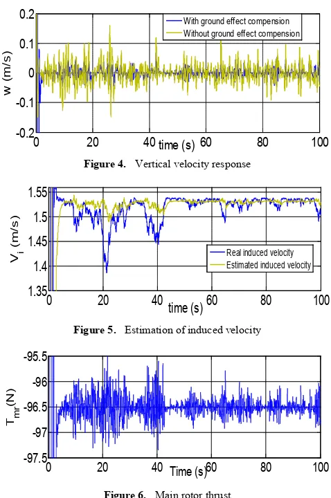
col < 200/s), are taken into account in the [image:5.595.311.550.71.431.2]simulation model. The horizontal wind disturbance is shown in Fig.1. The simulation result of the robust adaptive backstepping controller with ground effect compensation is depicted in Fig.2. It is clear that altitude tracking performance is improved by compensating the ground effect, while Fig.3 indicates that large deviation appears at the altitude tracking without ground effect compensation near ground surface. The linear velocity in the z direction is slightly fluctuating as illustrated in Fig.4.
Figure 1. Wind disturbance to test controller
Figure 2. Behaviour of altitude with ground effect compensation
Figure 3. Behaviour of altitude without ground effect compensation
Figure 4. Vertical velocity response
Figure 5. Estimation of induced velocity
Figure 6. Main rotor thrust
[image:5.595.59.294.384.613.2]Fig.5 shows that the estimated induced velocity is very close to the real induced velocity, with maximum estimation error of 0.1 m/s in the presence of ground effect. Fig.6 represents the variation in hovering thrust due to ground effect and external wind gusts near ground surface. The control input obtained using the robust adaptive backstepping controller is shown in Fig.7. It doesn't exceed the constraints for altitude control of a small helicopter. It can effectively compensate the ground effect as well as the external wind gusts effect, and the UAH can hover near ground surface.
Figure 7. Control input
6. Conclusion
In this paper, a nonlinear robustadaptive backstepping
0 20 40 60 80 100
0 5 10
time (s)
G
ust
ve
lo
ci
ty
(
m/
s)
0 10 20 30 40 50 60 70 80 90 100
0 0.2 0.4 0.6 0.8 1
time (s)
A
lti
tude (
m
)
Desired altitude Actual altitude
0 20 40 60 80 100
0.2 0.3 0.4 0.5 0.6 0.7
time (s)
A
lti
tude (
m
)
Desired altitude Actual altitude
0 20 40 60 80 100
-0.2 -0.1 0 0.1 0.2
time (s)
w
(m/
s)
With ground effect compension Without ground effect compension
0 20 40 60 80 100
1.35 1.4 1.45 1.5 1.55
time (s)
V i
(
m/
s
)
Real induced velocity Estimated induced velocity
0 20 40 60 80 100
-97.5 -97 -96.5 -96 -95.5
Time (s)
T m
r
(N
)
0 20 40 60 80 100
5 5.1 5.2
time (s)
C
o
llec
tiv
e
pi
tc
h
(
d
eg
[image:5.595.318.544.589.680.2]control scheme for the altitude control of a small scale helicopter near ground surface based on control Lyapunov approach is demonstrated. The algorithm controls the altitude dynamics of a VARIO small-scale helicopter. The simulation results clearly investigated the robustness of the proposed controller by tracking the altitude of the helicopter in the presence of ground effect and external wind gusts. Future works will deal with the implementation of the proposed autonomous flight control method on the real system and flight test to prove its feasibility in real applications.
REFERENCES
[1] Xiaodong Wang and Xiaoguang Zhao, “A practical survey on the flight control system of small-scale unmanned helicopter”, 7th World Congress on Intelligent Control and Automation (WCICA 2008), pp.364–369, 2008.
[2] Adnan Martini, François Léonard, and Gabriel Abba, “Dynamic Modelling and Stability Analysis of Model-Scale Helicopters Under Wind Gust”, J Intell Robot Syst (2009) 54:647–686.
[3] Xilin Yang, Hemanshu Pota, and Matt Garratt, “Design of a Gust Attenuation Controller for Landing Operations of Unmanned Autonomous Helicopters”, 18th IEEE International Conference on Control Applications, July 2009. [4] Kumeresan A. Danapalasingam, John-Josef Leth, Anders la Cour-Harbo and Morten Bisgaard, “Robust Helicopter Stabilization in the Face of Wind Disturbance”, 49th IEEE Conference on Decision and Control, December 15-17, 2010 Hilton Atlanta Hotel, Atlanta, GA, USA.
[5] H. Wang, A. A. Mian, D. Wang, and H. Duan, “Robust multi-mode flight control design for an unmanned helicopter based on multi-loop structure”, International Journal of Control, Automation, and Systems 7 (2009), 723-730. [6] T. Cheviron, F. Plestan, and A. Chriette, “A robust guidance
and control scheme of an autonomous scale helicopter in presence of wind gusts”, International Journal of Control, Vol. 82, No. 12 December 2009, 2206-2220.
[7] K. P. Tee, S. S. Ge, and F. E. H. Tay, “Adaptive neural network control for helicopter in vertical flight”, IEEE Transaction on Control System and Technology, Vol.16, No.4, pp.753-762, 2008.
[8] Alejandro Dzul, Rogelio Lozano and Pedro Castillo, “Adaptive Altitude Control for a Small Helicopter in a Vertical Flying Stand”, Proceedings of the 42nd IEEE Conference on Decision and Control Maui, Hawaii USA, December 2003.
[9] Keng Peng Tee, Shuzhi Sam Ge, and Francis E. H. Tay, “Adaptive Neural Network Control for Helicopters in Vertical Flight”, IEEE Transactions on Control Systems Technology, Vol. 16, No. 4, July 2008.
[10] Jongkwon Kim, Soohong Park, and Cheolsoon Jang,“Control System design for an Unmanned Helicopter”, http://www.aciar2005.ait.ac.th/CD/F-27.pdf (cited on 13th of September, 2011)
[11] J. Kaloust, C. Ham, and Z. Qu, “Nonlinear autopilot control design for a 2-DOF helicopter model”, IEE Proc., Control Theory Appl. -- Volume 144, Issue 6, p.612–616, November 1997.
[12] Kenichiro Nonaka and Hirokazu Sugizaki, “Integral Sliding Mode Altitude Control for a Small Model Helicopter with Ground Effect Compensation,” American Control Conference on O'Farrell Street, San Francisco, CA, USA June 29 - July 01, 2011.
[13] Tushar. K. Roy, Matt Garratt, Hemanshu R. Pota and Mahendra Kumar Samal, “Robust Altitude Control for a Small Helicopter by Considering the Ground Effect Compensation,” The 10th World Congress on Intelligent Control and Automation ( WCICA), pp. 1796-1800, July 6-8, Beijing, China, 2012.
[14] J. Gordon Leishman, “Principles of Helicopter Aerodynamics”, Second edition, 2006.
[15] Tushar. K. Roy, Matt Garratt, Hemanshu R. Pota and Hamid Teimoori, “ Robust Altitude Control of an Unmanned Autonomous Helicopter Using Backstepping,” IEEE The 10th World Congress on Intelligent Control and Automation ( WCICA), pp. 1650-1654, July 6-8, Beijing, China, 2012. [16] T. K. Royand M. Garratt , “Altitude Control of an Unmanned
Autonomous Helicopter via Robust Backstepping Controller under Horizontal Wind Gusts,” IEEE 7th International Conference on Electrical and Computer Engineering (ICECE’ 2012), pp. 771-774, December 20-22, 2012, Dhaka, Bangladesh.