QR-like Secret Data Hiding in Integer Wavelet
Transform Domain Images
Thanikaiselvan V*, Sivanantham S, Debopam Dey
School of Electronics Engineering, Vellore Institute of Technology, Vellore, Tamil Nadu, India
Received September 5, 2019; Revised December 17, 2019; Accepted December 24, 2019
Copyright©2019 by authors, all rights reserved. Authors agree that this article remains permanently open access under the terms of the Creative Commons Attribution License 4.0 International License
Abstract Steganography is the process of hiding secret
information in other multimedia files, like image, audio and video, such that any unauthorized person does not have any clue of the hidden secret data. Due to the recent computational advancements, there has been an increased risk in secure communication and thus, steganography has become one of the most researched domains in information security. In this paper, a novel method of steganography is approached where the cover image is scrambled using graph theory; then the secret data is embedded in the LH, HL and HH planes using LSB embedding of the cover image after applying Haar forward transform to get the embedded image. The secret data hidden in the cover image is first converted to a QR-like (Quick Response) image and then to be embedded in the cover media. The stego image is obtained after reverse Haar transform and descrambling of the embedded image. The proposed method when applied to a set of grayscale images, not only gave us stego images with greater embedding capacity but also high Peak Signal to Noise Ratio (PSNR) and a low Mean Square Error (MSE) and very appreciable Normalized Cross-Correlation (NCC) along with a good Structural Similarity Index Matrix (SSIM) when compared to the cover images.Keywords
Data Hiding, IWT, PSNR, QR Code, Scrambling1. Introduction
The amount of multimedia data being transmitted online is growing rapidly due to the swift development of internet technologies [1, 2]. This multimedia data can be of personal, public, governmental or military use. Since the governmental or military data is very sensitive in nature; it faces significant threats while being transmitted online. Thus, information security over the internet is one of the
most researched topics these days to not only protect the privacy of the individuals but also for national security and safety; and researches have taken a lot of data protection measures to transmit the multimedia data securely over the internet. Data security deals with shielding of data from unauthorized and illegal access [3]. These sensitive and critical data must be securely transmitted over the channel. For this purpose, network-specific encryption of data is not trustworthy and consistent; hence, we need an additional method to protect this sensitive data when it is transmitted over the channel so that the secret data cannot be retrieved even when the network routes have been accessed by an unauthorized party.
One of the most basic methods of data security is cryptography and it is one of the most researched topics in the literature [4]. Cryptography is an effective process of storing and transmitting sensitive multimedia data over a public channel or unsecured network where only the targeted individuals can read or process the data. At the receiver side, the cryptic data has to be then decrypted using various algorithms to reveal the original data.
Until recent years, researchers were encrypting texts directly using the basic text cryptosystems. Nowadays, since the size and nature of any multimedia file, be it audio or image is far greater and more complex as compared to that of a text, we can no longer apply these primitive text encryption methods for cryptography.
the secret data. Like any other technology, cryptography is not fool proof. Hence, we require several upgradations in the cryptic standards so that the developed cryptography algorithms do not become obvious to the third party while using the recent advancements in computing.
Another form of information hiding method, which uses a digital watermark, embedded by the sender to authenticate the genuineness of the information shared is known as watermarking [7]. Watermarking is used as a platform for security to protect the data from infringements. Digital watermarks are mainly used for copyright protection, authentication, and tampering recovery.
The most secure one-on-one communication technique is steganography [8-11]. The principle behind steganography simple, the unauthorized party must not have a clue of what is being transferred. The art of hiding things is known as steganography, where the secret data is concealed in the cover media while ensuring that the distortion in the cover media is minimum. If the amount of distortion increases, then it may give the third party a hint that some secret data may be stored and be transmitted in the cover media. The cover media can contain images, audio or video to hide secret data.
We can segregate steganography into irreversible and reversible steganography [12]. We use reversible steganography where the original image is sensitive and cannot be modified such as in defence, satellite a and medical imaging. In recent years, steganography based on adaptive pixel selection [1] and other methods like EMD is popular as compared to the previously used primitive steganography which was primarily based on difference expansion and histogram shifting.
We can expect little to moderate distortion in irreversible steganography. The cover media, which are used to carry the secret message, are known as the stego media. It uses the perceptibility of the human eye and transmits the stego media over the channel after intelligently embedding it. At the receiver end, we can easily retrieve the data using various algorithms. Steganography can be classified as spatial domain steganography and transform domain steganography. Both have many data embedding and compatible extraction techniques. Transform-domain steganography is more robust and prone to steganalysis while spatial-domain steganography deals with high data-holding capacity.
The most common steganographic technique in the spatial domain is the least significant bit (LSB) substitution [13, 22]. The LSB method is not prone to steganalysis tools and can be easily detected, despite having an appreciable embedding capacity. Thus, various work has been going on to make LSB prone to steganalysis. LSB Matching Revisited [14] (LSBMR) is one of the techniques being researched upon to solve this problem along with a series of methods which include the combination of Pixel Value Differencing (PVD) and LSB to improve the steganography performance [15].
Discrete Fourier Transform (DFT), Discrete Cosine
Transform (DCT) and Discrete Wavelet Transform (DWT) [16] are the most commonly used signal transforms. DWT is more preferred in steganography due to its spatial frequency local characteristics and multiresolution analysis compared to DCT [17, 18].
Transfer domain stenography involves hiding of data in transfer domain that is usually in Discrete Cosine Transform (DCT), Fourier Transform, Fast Fourier Transform or Discrete Wavelet Transform (DWT), which is different from spatial domain stenography. For instance, Discrete Wavelet Transform of image [19,20] can be shown in terms of its coefficients in the frequency domain. It represents the repetitive nature of the image pixels. The process of hiding the secret image on the transformed image using DWT is called Transform domain stenography [21]. The image is brought back in the spatial domain resulting in stego image. This process is called Inverse DWT. The user follows the same algorithm to retrieve back the original image. Increased security and better data obscurity are some advantages of transform domain stenography. This error can be reduced further by implementing some optimization techniques.
Imperceptibility is the factor that defines the complication involved to find the dissimilarity between stego and cover image [4]. A possible alteration in the output image with the secret image hidden can be estimated by PSNR- Peak Signal to Noise Ratio. Performance of stenography algorithms, security and their capacity can be assessed by multiple indicators. Embedding capacity refers to the amount of secret message that can be embedded in an image.
The remaining paper is segregated as follows. Section 2 deals with the previous works that have been done in steganography with LSB encryption, graph theory, and Haar IWT. Section 3 deals with the proposed algorithm. Section 4 and 5 contain the observed results, discussion and conclusions respectively.
2. Related Work
2.1. Least Significant Bit Substitution
LSB substitution means taking a cover image and substituting its least significant bits with the most-significant bits of the secret image. Over the past few years, data hiding using LSB substitution has gained tremendous popularity due to its large data holding capacity. LSB substitution along with post-processing of the stego images like optimum pixel adjustment process can give us high-quality stego images with a good PSNR and low computational complexity.
The process of hiding data in cover images using the simple least significant bit substitution method is explained below.
grayscale image which can be represented as:
𝐼= {𝑥𝑖𝑗|0≤ 𝑖<𝑀𝐼, 0≤ 𝑗<𝑁𝐼, 𝑥𝑖𝑗∈
{0,1,2, … ,255}} (1) The secret message to be embedded consisting of n-bits can be given as
𝑀= {𝑚𝑖|0≤ 𝑖<𝑛, 𝑚𝑖∈{0,1}} (2) Now, if the n-bit secret message M has to be embedded in the k-rightmost bits of the cover image I, the secret message M has to be rearranged to form a k-bit virtual image 𝑀′represented as:
𝑀′= {𝑚′
𝑖|0≤ 𝑖<𝑛′,𝑚′𝑖∈{0,1, … , 2𝑘−1}} (3) where 𝑛′<𝑀𝐼 ∗ 𝑁𝐼. The mapping between the embedded message 𝑀′= {𝑚′𝑖} and the n-bit secret message
𝑀= {𝑚𝑖} is given as follows:
𝑚′
𝑖=∑𝑘−1𝑗=0𝑚𝑖∗𝑘+𝑗𝑋 2𝑘−1−𝑗 (4) Bit plane slicing of the cover image is done to separate all the bit planes of the image. Then, the least significant bit plane, i.e., the 0-bit plane of the cover image is replaced with the secret message𝑚′𝑖. The cover image is then reconstructed to form the stego image as:
𝑥′
𝑙𝑖 = 𝑥𝑙𝑖− 𝑥𝑙𝑖𝑚𝑜𝑑 2𝑘+ 𝑚′𝑖 (5) where 𝑥′𝑙𝑖 is the modified stego-pixel.
At the extraction side, the k-bit LSB of the selected pixels can be readily extracted and recovered by using the following equation:
𝑚′
𝑖= 𝑥𝑙𝑖𝑚𝑜𝑑 2𝑘 (6) 2.2. Graph Theory and Graceful Graph Generation
The study of points and lines is known as graph theory. A graph G (V, E) can be represented as a function of vertices (V) which are linked with lines or curves called edges (E). In steganography, nodes can be considered as the pixels or pixels coefficients and the connection between two nodes are called edges. Hence, using graph theory, we can generate random traversing algorithms which can be in turn used in steganography algorithms as shown by V. Thanikaiselvan, et. al.
2.3. Method for Graph Generation
As discussed above, the pixel coefficients of an image are known as nodes, and we can easily derive four series S1,
S2, S3, S4 as mentioned below using the number of Nodes
(N):
𝑆1= [2𝑚, 2𝑚 −1, 2𝑚 −2, … ,𝑚+ 1] (7) where ‘m’ is an integer and can be derived by m=N/4 where
N is the number of nodes in the image. N must be a multiple of 4.
𝑆2= [𝑚𝑠(1) +𝜌(1),𝑚𝑠(2) +𝜌(2), … ,𝑚𝑠(𝑚) +𝜌(𝑚)] (8)
where 𝑚𝑠(𝑖) is the ith member of the series {m, m-1, m-2, …, (m-N/4)+1} and 𝜌(𝑖) is the ith member of the series (𝜌) which can be found by the random assembling of the constituents of “𝑚𝑠”.
𝑆3can be generated with the elements of “𝜌” as:
𝑆3= [𝜌(𝑚),𝜌(𝑚 −1), … ,𝜌(1)] (9)
𝑆4is a series of “m” zeroes:
𝑆4= [0,0,0, … ] (10) We can generate a graceful graph with the help of Node Sequence (𝑁𝑆), Edge Numbers (E), series (S) and a new series ‘A’ which can be calculated by adding ‘E’ and ‘S’.
2.4. Illustration of Graph Generation
An illustration of graceful graph generation is given as below:
Suppose a 4*4 matrix with sixteen elements considered. Thus, N=16.
Step 1. Generating series𝑆1. Since N is given, m can be calculated by m=N/4. Therefore, m=4. Thus, 𝑆1 is given by:
𝑆1= [8,7,6,5] (11) Step 2. Using the above equation, m(s)= [4,3,2,1], and 𝜌 can be obtained by the random arrangement of m(s), 𝜌= [2,4,3,1]. Thus, S2can be generated as:
𝑆2= [6,7,5,2] (12) Step 3. Similarly, S3 can be generated by substituting 𝜌 in the above equation.
𝑆3= [1,3,4,2] (13) Step 4. Since q=4, S4 can be generated as:
𝑆4= [0,0,0,0] (14) Step 5. Therefore, S can be generated by concatenating
[𝑆1,𝑆2,𝑆3,𝑆4]
𝑆= [8 7 6 5 6 7 5 2 1 3 4 2 0 0 0 0] (15)
Step 6. Generation of graceful graph table for random coefficient selection is given below:
Step 6(a). Calculating Node Sequence (𝑁𝑆) depending on the total nodes (N) and tabulating it:
𝑁𝑆= [1, 2, 3, 4, … ,𝑁] (16) Step 6(b). Formulating the edge series E= [1, 2, 3, …, N-1] where the first member of E will be placed directly below the second member of 𝑁𝑆.
Step 6(c). Arranging S in a table with the first element of S under the first element of 𝑁𝑆 and then, striking out the first element of S.
Step 6(d). Calculating 𝐴=𝐸+𝑆
Step 6(e). A graceful graph is obtained using series S and A.
Table 1. Generation of graceful graph table
Node Sequence (𝑁𝑆) 1 2 3 4 5 6 7 8 9 10 11 12 13 14 15 16
Edge Number (E) 1 2 3 4 5 6 7 8 9 10 11 12 13 14 15
S 8 7 6 5 6 7 5 2 1 3 4 2 0 0 0 0
A=E+S 8 8 8 10 12 11 9 9 12 14 13 12 13 14 15
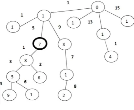
[image:4.595.70.285.210.387.2]The graceful graph generated from table 1 is shown in figure 1.
Figure 1. Graceful Graph
The graceful graph matrix 𝑅′that can be derived from the graceful graph is shown below:
𝑅′=�
7 8 6 5 9 12 11 10 3 2 14 4 1 16 13 15
�
2.5. Haar Integer Wavelet Transform
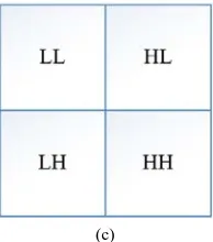
Haar IWT can be used to derive the coefficients of the cover image and then the least significant bit substitution can be applied in a lossless manner to get the stego image. After the one-dimensional Haar decomposition of the image, we get the following four parts namely, Approximation (LL), Horizontal (LH), Vertical (HL) and diagonal (HH). The decomposition of the images in the Haar transform is described in figure 2.
During the decomposition of an image with M rows and N columns, using wavelet transform, we assume that every row of size N is a one-dimensional signal. After applying Haar transform, the one-dimensional signal splits into two equal fragments of size 𝑁
2. This process is known as row processing and is repeated for the remaining M rows to form two signal bands, namely, the high-frequency band (H) and the low-frequency band (L) of size 𝑀 ∗𝑁
2using the following equations:
𝐻= (𝐶𝑜− 𝐶𝑒) (17)
𝐿=�𝐶𝑒+𝐹𝑙𝑜𝑜𝑟 �𝐻2�� (18) After the row processing, we can separate the odd and even rows of L and H bands as:
𝐻𝑜𝑑𝑑=𝑂𝑑𝑑𝑟𝑜𝑤𝑠𝑜𝑓𝐻
𝐿𝑜𝑑𝑑 = 𝑂𝑑𝑑𝑟𝑜𝑤𝑠𝑜𝑓𝐿
𝐻𝑒𝑣𝑒𝑛= 𝐸𝑣𝑒𝑛𝑟𝑜𝑤𝑠𝑜𝑓𝐻
𝐿𝑒𝑣𝑒𝑛=𝐸𝑣𝑒𝑛𝑟𝑜𝑤𝑠𝑜𝑓𝐿
[image:4.595.123.488.497.717.2]� (19)
The H and L bands are then reapplied to forward Haar transform independently, assuming that every column of size M as a one-dimensional signal. This process is known as column processing and it further segregates the H and L sub-bands into the abovementioned LL, LH, HL and HH bands, and each of size 𝑀2∗𝑁2 uses the following equations and is described in figure 3:
𝐿𝐻 = 𝐿𝑜𝑑𝑑− 𝐿𝑒𝑣𝑒𝑛
𝐿𝐿=𝐿𝑒𝑣𝑒𝑛+ 𝐹𝑙𝑜𝑜𝑟 �𝐿𝐻2�
𝐻𝐻= 𝐻𝑜𝑑𝑑− 𝐻𝑒𝑣𝑒𝑛
𝐻𝐿=𝐻𝑒𝑣𝑒𝑛+ 𝐹𝑙𝑜𝑜𝑟 �𝐻𝐻2�⎭⎪
⎬ ⎪ ⎫
(20)
In the decomposed cover image, after application of Haar transform; the LL sub-band contains the most important and substantial details when compared to the original image.
(a)
(b)
[image:5.595.373.470.79.189.2](c)
Figure 3. (a) Original Input Image (b) Image after forward IWT row processing (c) Image after forward IWT column processing
3. Proposed Work
Inspired by the integer wavelet transform and graph theory, the proposed method is subdivided into three parts which use different sets of algorithms for data hiding. Each algorithm, in turn, uses a set of keys which have to be used at the extraction site as well to retrieve the desired outputs. The embedding and extraction procedures of the proposed method are discussed here within.
3.1. Embedding Procedure
[image:5.595.88.518.295.724.2]The entire embedding procedure can be described in figure 4. The multimedia file to be hidden is first converted to a QR-like image by first converting the file to binary and then finally converted to a QR (Quick Response)-like image.
Figure 5 shows the QR-like image of a sample text message. This QR-like image generated is now considered the secret multimedia file.
Figure 5. QR-Like Image
3.2. Pixel Scrambling Using Graph Theory
Any image can be denoted as an n-dimensional matrix. The cover image is scrambled using the graceful graph matrix as mentioned above, where every node of the graph is considered as a pixel of the cover image and each node is mapped in the image matrix using the graceful graph formed. To illustrate this, let us consider R to be a 4*4 matrix in which all the matrix elements are considered as image pixels (or) nodes of the graph.
𝑅=�
1 2 3 4 5 6 7 8 9 10 11 12 13 14 15 16
�
Using graph theory, each pixel (or) node of the matrix can be mapped to new locations as shown in𝑅′. This gives us a scrambled image at the output as shown. The mapping done using graph theory can be described in figure 6.
𝑅′=�
7 8 6 5 9 12 11 10 3 2 14 4 1 16 13 15
[image:6.595.312.525.309.506.2]�
Figure 6. Mapping of pixel coefficients of an image using graph theory
Since graph theory leads to very less computational complexity, we can apply the same algorithm to the output of the previous operation to get extensive scrambling of the images. The degree of scrambling depends on the user as they can scramble the input image for ‘n’ times. Thus, a key can be generated and sent to the extraction site as the degree of scrambling.
3.3. Integer Wavelet Transform
The one-dimensional Haar Integer Wavelet Transform is applied on the scrambled image output of the graph theory. After applying both the row and column processing of the forward Haar transform, the input image (I) is decomposed into four subsequent sub-bands LL, LH, HL, and HH. After the forward Haar transform, of the input image, data can be embedded in the less significant sub-bands of the decomposed image, namely, LH, HL, and HH as shown in figure 7.
(a) (b)
(c) (d)
Figure 7. (a) Input Image (b) Image after forward IWT decomposition (c) Image after Data Embedding (d) Stego image after inverse IWT
[image:6.595.125.224.452.590.2](a)
(b) (c)
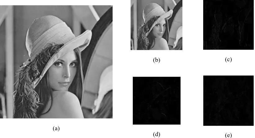
[image:7.595.91.502.82.304.2](d) (e)
Figure 8. (a) Cover Image: Lena (b) LL (c) HL (d) LH (e) HH forward Haar decomposition of (a)
The stego image is generated after inverse column processing and inverse row processing of the image in which data is embedded.
3.4. LSB Data Embedding
Least Significant Bit substitution is used to embed the data in the cover image after forward IWT decomposition of the cover image. Here, the bit planes of the secret image are separated along with the HL, LH and HH decomposed planes of the cover image.
The bit plane slicing of the cover image is done by:
𝐶𝑖=𝑀𝑜𝑑 �𝑓𝑙𝑜𝑜𝑟 �2𝐶𝑖�, 2� (21) where C is the cover image, 𝐶𝑖is the ith bit plane of C. We can separate the most significant bits of the message to be
hidden in the same procedure. The MSB of the secret message image (I) can be embedded in the cover image by:
𝐶′
𝑙𝑖 = 𝐶𝑙𝑖− 𝐶𝑙𝑖𝑚𝑜𝑑 2𝑘+ 𝑚′𝑖 (22) Here, the user can define the number of bits which have to be embedded in each plane of the image. It is not recommended to embed more than 4 bits in each plane for an optimal quality stego image otherwise, the image quality degrades.
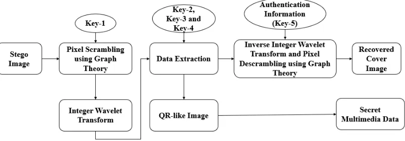
3.5. Extraction Procedure
Figure 9. Block Diagram of the Extraction Procedure
The stego image is again scrambled with the same degree as used during the embedding procedure. After the pixel scrambling, the stego image is again decomposed in LL, LH, HL and HH sub-bands. Then, the embedded secret message bits can be recovered from the LH, HL and HH bands by using the following equation:
𝑚′
𝑖= 𝐶𝑖 𝑚𝑜𝑑 2𝑘 (23)
where 𝑚′𝑖represents the extracted message bits of the secret image. Inverse IWT can be applied to the remaining image to recover the cover image again.
4. Results
The proposed method has been tested on ten different grayscale images, each of size 512*512. The performance characteristics of the output stego image have been compared with the cover image using Peak Signal to Noise Ratio (PSNR), Mean Square Error (MSE), Normalized Cross-Correlation (NCC) and Structural Similarity Index Matrix (SSIM) which are shown below from equations (24-27) where both the sizes of the cover image (C) and the stego image (S) are M*N.
𝑀𝑆𝐸=𝑀𝑁1 ∑ ∑ �𝐶𝑖=1𝑀 𝑁𝑗=1 𝑖,𝑗− 𝑆𝑖,𝑗�2 (24)
𝑃𝑆𝑁𝑅= 10𝑙𝑜𝑔10255∗255𝑀𝑆𝐸 𝑑𝐵 (25)
𝑁𝐶𝐶=∑𝑀𝑖=1∑𝑗=1𝑁 𝐶(𝑖,𝑗)∗𝑆(𝑖,𝑗)
∑ ∑𝑁 𝐶(𝑖,𝑗)2 𝑗=1 𝑀
𝑖=1 (26)
𝑆𝑆𝐼𝑀(𝐶,𝑆) = (2𝜇𝐶𝜇𝑆+𝑥1)∗(2𝜎𝐶𝑆+𝑥2)
(𝜇𝐶2+𝜇 𝑆 2+𝑥1)∗(𝜎
𝐶2+𝜎𝑆2+𝑥2) (27) where
𝜇𝐶is the mean pixel value of C;
𝜇𝑆is the mean pixel value of S;
𝜎𝐶2 is the variance of C;
𝜎𝑆2is the variance of S;
𝜎𝐶𝑆is the covariance of C and S;
𝑥1= (𝑘1𝐿)2and𝑥2= (𝑘2𝐿)2are used to stabilize the
division due to the weak denominator; L is the dynamic range of pixel values;
𝑘1=0.01 and𝑘2=0.03
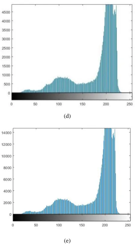
Histogram analysis of the cover image, scrambled image and stego image and their comparison gives us very similar results as observed from figure 10.
(a)
(b)
(d)
(e)
[image:9.595.62.287.76.482.2](f)
Figure 10. (a) Original Airplane; (b) Scrambled Airplane; (c) Stego Airplane; (d) Original Airplane-Histogram; (e) Scrambled Airplane-Histogram; (f) Stego Airplane-Histogram
[image:9.595.310.530.77.270.2]Table 2. Comparison between different images and their observed results
Image Dataset Bits embedded
per sub-band MSE PSNR NCC SSIM
Airplane 1 0.5629 50.3412 0.9998 0.9868
Airplane 2 2.4227 44.8211 0.9998 0.9211
Airplane 3 11.6128 37.5154 0.9998 0.7893
Airplane 4 42.0913 31.2343 0.9998 0.5864
Barb 1 0.5051 50.1060 0.9996 0.9825
Barb 2 2.1825 44.2831 0.9996 0.9419
Barb 3 10.4805 37.4977 0.9996 0.8341
Barb 4 48.1888 31.3353 0.9996 0.6559
Boat 1 0.6189 49.9454 0.9997 0.9629
Boat 2 2.6783 43.8863 0.9997 0.8892
Boat 3 10.4721 37.9644 0.9997 0.7467
Boat 4 39.4013 32.2097 0.9997 0.5589
Cameraman 1 0.5537 50.7320 0.9996 0.9900
Cameraman 2 2.1708 44.7986 0.9996 0.9633
Cameraman 3 10.0089 38.1609 0.9996 0.8716
Cameraman 4 41.4342 31.9912 0.9996 0.6653
Goldhill 1 0.5521 50.7449 0.9996 0.9876
Goldhill 2 2.1729 44.7944 0.9996 0.9598
Goldhill 3 9.9782 38.1743 0.9996 0.8818
Goldhill 4 41.0669 32.0299 0.9996 0.7092
Home 1 0.5363 50.8710 0.9998 0.9342
Home 2 2.1951 44.7503 0.9998 0.8261
Home 3 10.5031 37.9516 0.9998 0.6302
Home 4 35.8253 32.6229 0.9998 0.4154
Lena 1 0.5542 50.7283 0.9996 0.9786
Lena 2 2.1806 44.7791 0.9996 0.9231
Lena 3 9.9233 38.1982 0.9996 0.7771
Lena 4 39.6343 32.1841 0.9996 0.5319
Mandrill 1 0.5436 50.5584 0.9996 0.9887
Mandrill 2 2.1751 44.2978 0.9996 0.9321
Mandrill 3 10.9482 38.2901 0.9996 0.8274
Mandrill 4 38.3695 32.7018 0.9996 0.5880
Peppers 1 0.5132 50.9083 0.9996 0.9814
Peppers 2 2.7942 43.6943 0.9996 0.9246
Peppers 3 10.6401 37.4283 0.9996 0.7994
Peppers 4 39.1964 31.9897 0.9996 0.5772
Tiffany 1 0.6419 49.7352 0.9998 0.9555
Tiffany 2 2.1498 44.1376 0.9998 0.9128
Tiffany 3 11.2976 38.0731 0.9998 0.8432
[image:10.595.71.526.92.694.2]The proposed method also leads to minimal computational complexity. The average time required for the entire embedding and extraction combined is found to be 4.5512 seconds. The time complexity of the same can be given in Big-O notation as O(N) since the algorithm is operated sequentially for each pixel.
5. Conclusions
We can prove the high capacity, imperceptibility and robustness of the output stego image form the proposed method in terms of PSNR, MSE, NCC and SSIM which gives us very convincing results as compared to other methods. High capacity embedding is achieved through 4-bit embedding in the image sub-bands. High robustness of the stego image is attained through QR-like image formation of the data to be hidden in the image using graph theory and Haar transform. The proposed method can be adapted with various other data embedding algorithms and their performance can be analyzed as a future extension.
Acknowledgements
This work was supported by the Defense Research and Development Organization (DRDO), Government of India (Grant Number: ERIP/ER/1503222/M/01/1729). We would also like to thank the management of Vellore Institute of Technology, Vellore for supporting us with all the requirements to carry the research.
REFERENCES
[1] H. Jung, Data hiding scheme improving embedding capacity using mixed PVD and LSB on bit plane, J. Real-Time Image Process. 14 (1) (2018) 127–136.
[2] Hua Zhang, Liting Hu, A data hiding scheme based on multidirectional line encoding and integer wavelet transform, J. Image Communication. 78 (2019) 331–344.
[3] Y. Chen, Comment on ‘‘Cheating prevention in visual cryptography’’, IEEE Trans. Image Process. 21 (7) (2012) 3319–3323.
[4] V. Thanikaiselvan, et al, A Graph Theory Practice on Transformed Image: A Random Image Steganography, The Scientific World Journal.Volume 2013, Article ID 464107
[5] Hui-Yu Huang, Shih-Hsu Chang, A Lossless Data Hiding based on Discrete Haar Wavelet Transform; in the proceedings of IEEE International Conference on Computer and Information Technology, 2010, pp. 1554-1559
[6] Sara Tedmori, Nijad Al-Najdawi, Image cryptographic algorithm based on the Haar wavelet transform, J. Information Sciences 269 (2014) 21–34
[7] M. Cancellaro, et al. A commutative digital image
watermarking and encryption method in the tree structured Haar transform domain, J. Signal Processing: Image Communication 26 (2011)1–12
[8] V. Thanikaiselvan, P. Arulmozhivarman, RAND -STEG: an integer wavelet transform domain digital image random steganography using knight’s tour, J. Security Comm. Networks 2015; 8:2374–2382
[9] Yang H, Sun X, Sun G. A high-capacity image data hiding scheme using adaptive LSB substitution. Radio Engineering Journal 2009; 10(4):509–516.
[10]Yang CH, Weng CY, Wang SJ, Sun HM. Adaptive data hiding in edge areas of images with spatial LSB domain systems. IEEE Transformations on Information Forensics and Security 2008; 3 (3):488–497.
[11]Banoci V, Bugar G, Levicky D, Klenovicova Z. A novel JPEG steganography method based on modulus function with histogram analysis. Radio Engineering Journal 2012; 21(12):758–763.
[12]V. Thanikaiselvan, P. Arulmozhivarman, High Security Image Steganography Using IWT and Graph Theory, in the proceedings of IEEE International Conference on Signal and Image Processing Applications, 2013, pp. 337-342.
[13]Hamad A. Al-Korbi, et al. High-Capacity Image Steganography Based on Haar DWT for Hiding Miscellaneous Data, in the proceedings of IEEE Jordan Conference on Applied Electrical Engineering and Computing Technologies, 2015.
[14]C.K. Chan, L.M. Chen, "Hiding data in images by simple LSB substitution", Pattern recognition, Vol.37 (3), pp .469 -474, 2004.
[15]Yang, C.H., Weng, C.Y., Wang, S.J., & Sun, H.M., "Adaptive data hiding in edge areas of images with spatial LSB domain systems", IEEE Transactions on Information Forensics and Security. Vol. 3(3), pp.4SS-497,200S.
[16]P.C. Mali, D. Dutta Majumdar; An analytical comparative study of the Haar transform in the context of image processing, J. Pattern Recognition Letters l0 (1989) pp. 87-92
[17]Essam H. Houssein, et al. An Image Steganography Algorithm using Haar Discrete Wavelet Transform with Advanced Encryption System, in the Proceedings of the Federated Conference on Computer Science and Information Systems, 2016, pp. 641–644
[18]Ahmad Shaik, V. Thanikaiselvan, Comparative analysis of integer wavelet transforms in reversible data hiding using threshold-based histogram modification, J. Journal of King Saud University – Computer and Information Sciences, https://doi.org/10.1016/j.jksuci.2018.06.001
[19]Saied Fazli Sajad Gholamrezaei, and Amir Bazrafshan, "Advanced Wavelet Based Steganography for Colored Images", in Proc. International Congress on Ultra-Modern Telecommunications and Control Systems and Workshops (ICUMT),2010, pp 377-3S0
[21]Shrikant P Mudnur, et al, Hiding the Secret Image Using Two Cover Images for Enhancing the Robustness of the Stego Image Using Haar DWT and LSB Techniques, in the proceedings of Conference on Information and Communication Technology, 2018.