Different Kinds of Modern Technique to Develop
Various Information Systems
Feri Sulianta
*, Ai Rosita, Ulil Surtia Zulpratita, Heri Heryono, Eka Angga Laksana, Sy. Yuliani
University of Widyatama, Bandung, Indonesia
Copyright©2019 by authors, all rights reserved. Authors agree that this article remains permanently open access under the terms of the Creative Commons Attribution License 4.0 International License
Abstract Basically, information system design is
fundamental to the long-term sustainability of information systems. Information system architecture is a reference in developing and building new information systems if the current system is no longer able to support the activities of an organization or company. There are various information system development methods and there are various information systems architecture models. The choice of using methods and models must be carefully considered so that the information system created is right on target. A variety of techniques will be introduced to enrich knowledge in choosing development methods and architectural models that suit the needs of the organization.Keyword Architecture, Software Engineering,
Information System, Method, Model1. Introduction
Computer technology and information can no longer be separated from human activities. We are very dependent on computers. Humans are very dependent on the existence of information systems in many activities, including in business. If only the information system is abolished, it can be ascertained that in a matter of weeks, the activities and business processes will be abandoned. This can also have an impact on the business world. Without an information system, companies that are very dependent on the existence of an information system can no longer operate and even experience bankruptcy.
Information systems have been seen as a driving force for human activities and companies.
There are many information systems used by many companies, this depends on the needs and functionality supported by the information system.
2. Information System Classification
Some classifications of Computer Based Information Systems were put forward by Kroenke in 1992, namely:Classification based on organizational structure: • Departmental Information System: Information
system used by a department in an organization or company.
• Examples: Accounting Information System, Transaction Processing System, Billing System, etc. • Enterprise Information System: An information
system that includes departments within a company and generally is an integrated system that supports various functions of departments in a company. • Interorganizational System: a system that is able to
integrate business processes between companies, this system is generally supported by Electronic Data Interchange (EDI) in exchanging data between different company systems.
Classification based on organization in internal scope: • Personal information system: this information system
is generally used by individuals in a company. Example: various applications included in office automation systems, such as word processing applications, electronic spreadsheets, e-mail client applications, scheduling applications.
• Working group information system: a system aimed at supporting collaboration and work of groups or teams. For example: an application with a teleconference feature.
Classification based on the functional area of the company (external and internal functions that exist in the company or organization, sometimes also referring to business processes in departments in the company): • Accounting Information System
• Finance Information System • Manufacturing Information System • Marketing Information System
• Human Resources Management Information System Classification based on the support provided by the information system:
• Transaction Processing System: the characteristics of this system are supporting repetitive, routine work, essential and critical activities, often used by workers at lower levels or administrative workers. Transaction Processing Systems generally become data sources for other information systems, for example sales transaction data in the Transaction Processing System, used to make accounting reports on Accounting Information Systems.
Example: Transaction system in supermarkets or minimarkets, information systems for borrowing books in libraries, systems for rental vehicles or systems used to manage bills on internet cafes.
• • Management Information System: This system is intended to support the functions and activities of managers and generally middle-level managers. Accumulated transactional reports summarized and displayed in the form of diagrams are one example of the features in the Management Information System. • • Office Automation System: this system is intended
to support office workers in their activities and this system also refers to information systems that are used individually or personally (Mahmudova,2018). • Example: various word processing applications,
electronic spreadsheets, e-mail client applications, scheduling applications, fax machines, timetable applications, e-calenders, e-calculators, etc.
• • Decision Support System: this system is intended to assist the role of middle level managers in making decisions, for example banking managers use Credit Approval Systems when analyzing the feasibility of customers to be given loans.
Note: Decision Support Systems are not intended to replace the duties of managers in making decisions, but are intended to provide input for managers in making decisions.
• Executive Information System: this system is intended for top managers to make strategic planning. The main feature of this application is the feature in digging information (Drill Down Information). Online Analytical Processing and data mining techniques are often used as the basis for building Executive Information Systems.
• Working Group Support Systems: a system aimed at helping the work of a team or group. Example: Lotus Notes Application.
• Artificial intelligence systems or expert systems (Intelligent Support Systems): this system is intended for expert workers such as doctors, researchers or scientists. This application has expertise features or can provide output like an expert. Example: a system that can detect cancer types or systems that is able to analyze radioactive waste.
• Knowledge Information System: this system is intended to manage knowledge, for example: e-learning applications that have discussion forum features and information or knowledge digitalization processes.
3. Information System Architecture
Development
Designing information system architecture is part of the software engineering process which is then followed up by obtaining various information resources to create information systems. Looking at several points of view, information system architecture is defined as follows as the information expert says:
• Mapping and planning information needs in an organization or company (Turban, McLean, Wetherbe, 1999).
• A certain form of using information technology to achieve goals also functions carefully in an organization or company (Laudon & Lauon, 1998). • Design of a computer information system as a whole
to meet organizational needs (Zwass, 1998).
• Defining information system requirements carefully in the form of a design involving various components of information resources which become a blueprint for building information systems (Feri Sulianta, 2014).
As stated earlier regarding the important role in modeling information system architecture, modeling information system architecture is basically intended to: • Build an information system that is right on target,
effective, efficient and quality.
• Become a reference or blueprint for building information systems.
• Used as system documentation (Melese, et.al 2018). • Used as a reference in understanding the mechanism
of information systems.
• Used as a basis for maintaining a long-term information system.
Figure 1. Currently modeling information systems is done using modeling software (Computer Aided Software Engineering)
As the development of information technology and the creation of software such as word applications or graphic applications, system developers use these devices in drawing system architecture models. Drawing models with word applications or graphical applications is no different from how to draw a template flowchart, because it allows the occurrence of a high risk of error which is different from using a special application in modeling information systems. This application is known as CASE (Computer Aided Software Engineering).
4. Modeling Tool
Basically modeling is only part of the steps that must be passed in building an information system. Whereas, currently modeling information system architecture has been seconded to various modeling software.
From the various types of information systems that have been introduced before, the development of information systems is carried out after going through a series of long processes, one of which is the creation of a system architecture or modeling the system. There are many ways and many tools that can be used to create information system architectures. This is intended to facilitate us in analyzing, documenting, building and maintaining information systems.
The ease of building a system architecture effectively and efficiently is now enabled by the CASE Tool software
tools. The CASE Tool includes a Modeling Tool that has various functions such as:
• Model information systems and processes that occur in the system.
• Document information systems
• Provide flexibility and variety of choices in modeling information systems.
• Designing a programming interface (mockup). • Make work scheduling in designing information
systems carefully.
• Automatically generate programming codes.
• Creating a prototype, the information system as a prototype that will be used as the basis for making actual applications.
• Media in communicating and determining client needs regarding the procurement of software.
• Reference in studying the current system and further system development.
Many modeling applications can be used for this purpose. Some applications are categorized as commercial and paid, such as: Rational Rose, IBM RSA, Microsoft Project, Power Designer, Mockup Builder. Some provide a shareware or trial version to be used for a certain period of time. Some applications may be used forever with limited features, for example the Balsamiq Mockup application.
[image:3.595.69.527.76.391.2]UML, Argo UML, etc. Each of these applications generally has its own features and advantages that are not found in other applications.
Some of the below are examples of application interfaces used in modeling and developing information systems:
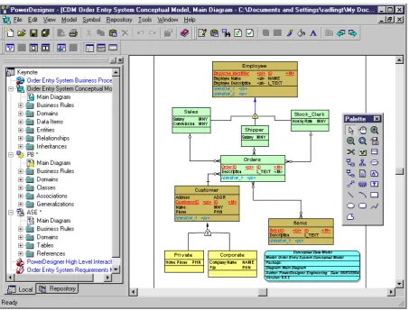
Figure 2. Power Designer 6.0 is used to make data flow diagrams (DFD Level 1)
[image:4.595.69.525.129.364.2] [image:4.595.73.527.388.732.2]Power designer applications are intended to model information systems before they are encoded using a programming language. The type of diagram used is known as the term namely: Context Diagram and Data
Flow Diagram or Data Flow Diagram. This diagram can be generalized and detailed to reveal business processes in detail.
Figure 4. Interface of CA ERwin Data Modeler [Source: Erwin.com]
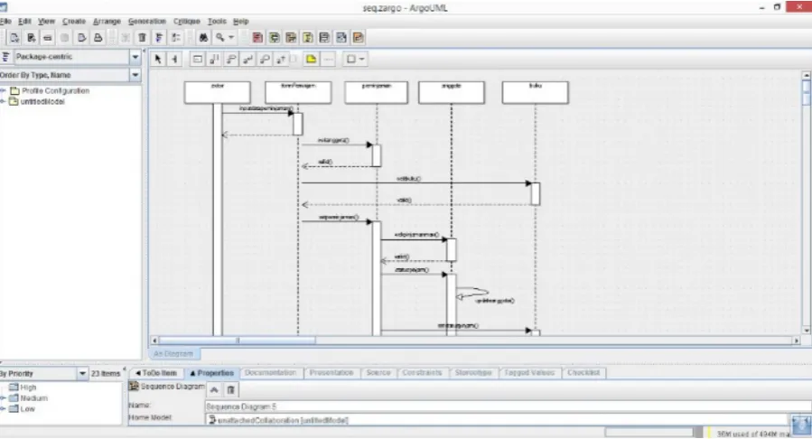
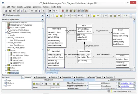
[image:5.595.70.527.138.433.2] [image:5.595.72.526.450.693.2]Figure 6. UML Argo used to create Sequence Diagrams
Another data modeling application is CA ERwin Data Modeler for modeling databases. This application also has documentation features. It supports object-based modeling, and the modeling results can be transformed into various other modeler tools. This application supports database design such as: DB2, IDS (Informix), MySQL, ODBC, Oracle, Progress. SAS, SQL Server, Sybase, Sybase IQ, and Teradata.
Some of the above images present the creation of models such as Use Case, Class Diagram, Sequences Diagram. These models are models that are made if you want to build an application based on object-based modeling.
Modeling tools can generally be further empowered to generate programming code, as exemplified in the figure below about transforming Class Diagrams based on objects into programming codes.
The development of various CASE Tool applications greatly facilitates developers in building information systems. If previously we talked about the design model, furthermore CASE Tool was also intended for a broader need, namely managing the creation of information systems, which involved scheduling, managerial teams, system maintenance, even making information system
prototypes that could be operated.
5. Specific Developer Tool
CASE Prototyping Tool in Data Drilling
One type of system known as the Executive Information System generally has the ability to drill down (dig) information. With the abundance of software products today, without having to model or write programming code, system analysts or programmers can first experiment with applications such as data mining and OLAP tools to study data and the need for 'strategic applications for the needs of top managers' which will later made.
The OLAP tool used to experiment with data before creating an Executive Information System can be seen as modeling and is included in the design phase of system development.
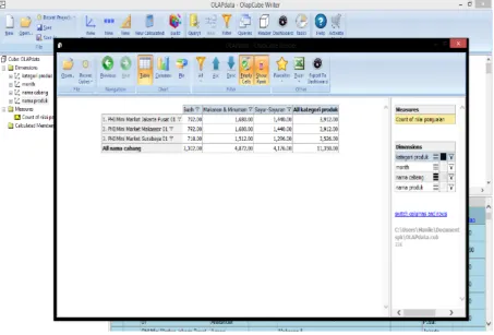
[image:6.595.73.523.79.322.2]Figure 7. Analyzes the sales value of product categories in each branch
6. Others Software Engineering Tool
Computer-based information systems do not have to always be built by typing programming codes. If the application is intended only to handle work whose scope is limited and is only intended to 'support' individual work in offices (known as the Office Automation System), it is not recommended to use large resources only to meet the needs of information systems with a small and simple scope. Some end user application products have been able to build applications to meet needs with limited scope.Such applications actually have good performance, especially in terms of user friendliness, for example the Microsoft Excel application which has the following features:
• Macro Programming and Visual Basic Application. • Arithmetic functions ready to use.
• Generator diagram (chart generator).
• Worksheets (spreadsheets) that can hold lots of data. • Other automatic features in managing data in a
spreadsheet.
Note: Macro is a small program that consists of a collection of commands that are run in an office package application program environment (including: Excel, Access and Word). Macro is basically designed to make it easier to work with Microsoft Office package applications. Macro commands are actually VBA commands, so you can say VBA is a superset of Macro. While Visual Basic Application is a Visual Basic programming language that is integrated in the application. Inserting Macros and Visual Basic Appliaction on Excel objects is much easier than having to build information systems using Visual Basic.
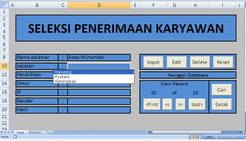
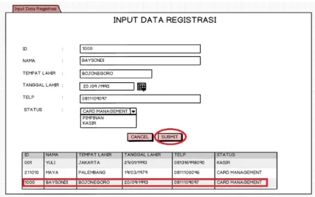
[image:7.595.72.526.80.387.2]Figure 8. Input data in a program created using Excel - the data entered is stored in a separate spreadsheet
Below is a VBA program that is added to the Excel worksheet so that the application can save to a separate spreadsheet that functions like a database:
'Kode saat tombol Input ditekan Private Sub cmdInput_Click () 'wsDTBS adalah worksheet Database Set wsDtbs = Worksheets ("Database")
'BarisLanjut = record database setelah baris terakhir BarisLanjut = wsDtbs.Cells (Rows.Count, "A"). _ End (xlUp).Offset (1, 0).Row
'Jika nama pelamar belum diisi If Range ("D8").Value = "" Then
'Kotak pesan informasi nama pelamar belum diisi MsgBox "Nama pelamar belum diisi", _
vbOKOnly + vbInformation, "Nama Pelamar Kosong"
'Seleksi sel D8 Range ("D8").Select 'Keluar dari Sub Procedure Exit Sub
'Jika umur pelamar belum diisi ElseIf Range ("D14").Value = "" Then MsgBox "Umur pelamar belum diisi", _
vbOKOnly + vbInformation, "Umur Pelamar Kosong"
'Seleksi sel D14 Range ("D14").Select 'Keluar dari Sub Procedure Exit Sub
'Jika IP pelamar belum diisi
ElseIf Range ("D16").Value = "" Then MsgBox "IP pelamar belum diisi", _
vbOKOnly + vbInformation, "IP Pelamar Kosong" 'Seleksi sel D16
Range ("D16").Select 'Keluar dari Sub Procedure Exit Sub
End If
'Input nama pelamar ke dalam worksheet database kolom A
wsDtbs.Cells(BarisLanjut, 1).Value = Range("D8").Value
'Input jabatan yang dilamar ke dalam kolom B
wsDtbs.Cells(BarisLanjut, 2).Value = Range("D10").Value
'Input pendidikan pelamar ke dalam kolom C
wsDtbs.Cells(BarisLanjut, 3).Value = Range("D12").Value
'Input umur pelamar ke dalam kolom D
wsDtbs.Cells(BarisLanjut, 4).Value = Range("D14").Value
'Input IP pelamar ke dalam kolom E
wsDtbs.Cells(BarisLanjut, 5).Value = Range("D16").Value
'Input jenis kelamin ke dalam kolom F
wsDtbs.Cells(BarisLanjut, 6).Value = Range("D18").Value
'Input hasil seleksi ke dalam kolom G
wsDtbs.Cells(BarisLanjut, 7).FormulaR1C1 = _ "=SELEKSI(RC[-5],RC[-4],RC[-3],RC[-2],RC[-1])" 'Panggil Sub Procedure cmdLast_Click (tombol Last) Call cmdLast_Click
End Sub
[image:8.595.86.506.79.320.2]programming codes. Many present-day applications have a ready-made model (prototype) which is one of the choices in modeling information systems. Information specialists can directly model the system needed by the user with prototyping tools which are then directly applied by the user.
Template features, object-based programming, prototyping and various features in programming languages such as wizards, builders or generators minimize programmers in writing programming codes.
The database can also be awakened by its prototype (made instantly) without having to define one by one the attributes and table structure. Generally the database is used as a pilot and will be redesigned or database
prototypes converted into a large scale database environment if it is to be used as a database in information systems. For example, the database blueprint is done using Microsoft Access and then converted (upsize) to the Oracle database or MYSQL database.
The existence of the wizard features, templates and generators are the basis of the prototyping tool before the actual application is created. The report builder feature, form builder, project generator or wizard facilities for programming tools show that the programming tool has the capacity to make prototyping. Even in many cases, the results of prototyping can be directly used as ready-to-use applications after going through several reviews of their functions and feasibility.
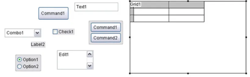
[image:9.595.92.502.261.388.2]Figure 9. Visual objects in Graphical User Interface (GUI) based programming
[image:9.595.95.494.291.739.2]Figure 11. Building a database with Database Builder
Note: The various facilities of the wizard are elements of the prototyping tool that enables programmers to make prototypes quickly. In some cases, prototypes can be used by users, and sometimes prototypes are used as models to build more complex information systems.
Some prototyping features commonly found in programming tools include: Application Wizard, Cross-Tab Wizard, Database Wizard, Documenting Wizard, Form Wizard, Graph Wizard, Import Wizard, Label Wizard, Local View Wizard, Mail Merge Wizard, One-To -Many Form Wizard, One-To-Many Report Wizard.
Prototyping tool in designing information system architecture interfaces
The Balsamiq Mockup application is intended to create application interface models such as the homepage interface or information system. This makes it easier for the system analyst or programmer to communicate to users about the form of the system that will be built.
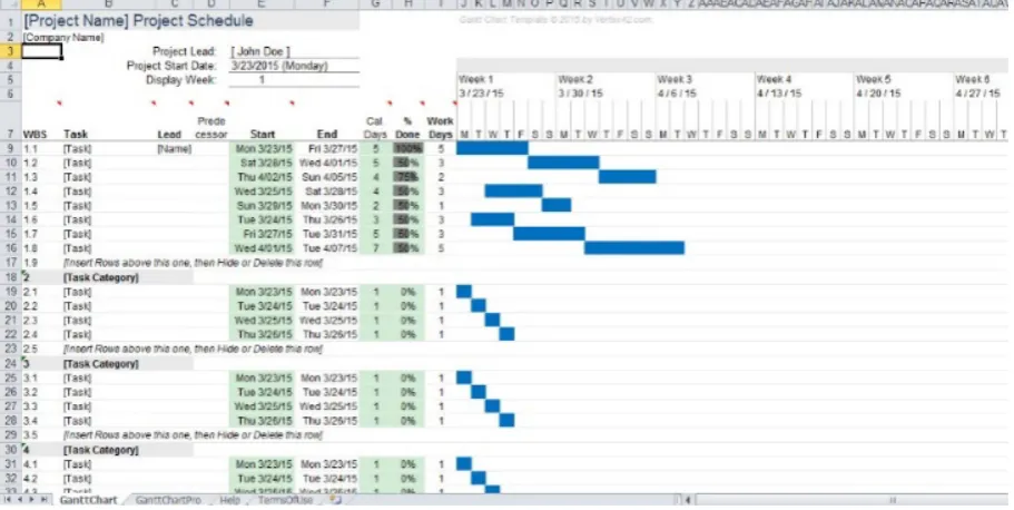
[image:10.595.71.524.440.723.2]Figure 13. Manage scheduling with the Gantt chart method in Excel
Application-based Project Management
Usually good application development uses project management knowledge in 'locking' the information system creation time is complete at the scheduled time. To meet this need an application with a Gantt chart scheduling approach that maps time-based actions and actions can be used.
Many tools can be used in software project management, even Excel can be used to create Gantt Charts which will be aimed at scheduling information system development.
If you want to use a special Gantt chart application, you can use a free application such as Gantt Project 2.7 Ostrava.
Some of the tools above are examples of the many tools used in designing and modeling information systems. This makes it easy for developers so that the software engineering process can be planned and meet the company's needs for information systems.
7. Conclusions
There are various information systems today, various tools in creating information system architectures that will generate applications, data (databases), information technology-based interfaces and services [18]. Even tools with analytical capabilities that exist today enable developers to experiment before creating an Executive Information System or Decision Support System.
For reasons of efficiency and effectiveness in making information systems, the latest techniques are needed that are able to catalyze various methods of developing information systems, so that information system projects take place without obstacles and synergize for each process,
and enable coordination between professionals involved in information system design projects.
There are many extra benefits in designing modern architecture, one of which is the automatic transformation of the information system model into a semi-finished or complete application.
Acknowledgements
This work is supported by Widyatama University.
REFERENCES
[1] Berthold. Hand. Intelligent Data Analysis: An Introduction. 2003 Second Edition.
[2] Feri Sulianta & Fajri R.Umbara. Excel Intelligent – Cara Pintar Membangun Strategi Bisnis. Elexmedia Komputindo Publisher. 2012.
[3] Feri Sulianta & Fajri R.Umbara. Teknik Hebat Merancang Aplikasi Instan Berkualitas. Elexmedia Komputindo Publisher. 2015.
[4] Feri Sulianta. Arsitektur Sistem Informasi. Penerbit Andi. 2017.
[5] Feri Sulianta. Data Mining. Elexmedia Komputindo Publisher. 2010.
[6] Feri Sulianta. OLAP Excel – Cara Hebat Excel Mengelola Data. Elexmedia Komputindo Publisher. 2011.
[7] James E. Purcell. Comparison of Software Development Lifecycle Methodologies. SANS Institute.
Modelling Techniques. 2012. Intech Open.
[9] Kroenke, D.M., 1992. Management Information System. Watsonville: Mitchell McGraw Hill.
[10]Marcus, Aaron. 1992. Graphic Design for Electronic Documents and User Interface. Addison Wesley.
[11]McLeod, Raymond, “Management Information System: Prentice Hall, 1989.
[12]Pokorny, J., Repa, V., Richta, K., Wojtkowski, W., Linger, H., Barry, C., Lang, M. (Eds.). Information Systems Development - Business Systems and Services: Modeling and Development. 2011. Springer.
[13]Pressman, Roger S, “Software Engineering: A practitioner’s approach 4th Edition”, Mc Graw Hill, 1997.
[14]Radhika D. Amlani. Comparison of different SDLC models. International Journal of Computer Applications & Information Technology. Vol. II, Issue I, January 2013 (ISSN: 2278-7720)
[15]Rumbaugh, James, Ivar Jacobson, Grady Booch, “The Unified Modelling Language Reference Manual Second Edition”, Addison-Wisley, 2005.
[16]Sommerville, Ian. 2011. Software Engineering.
Addison-Wesley.
[17]Turban, Efraim, Decision Support and Expert Systems: management Support System, Fourth Edition, Prentice-Hall, Inc., United States of America, 1995.
[18]Jabarullah, N.H., Shabbir, M.S., Abbas, M., Siddiqi, A.F. & Berti, S. (2019) Using random inquiry optimization method for provision of heat and cooling demand in hub systems for smart buildings, Sustainable Cities and Society, 47, 101475.
[19]Mahmudova, S. (2018). Methods of Organizing the Technological Process of Software Development. Review of Information Engineering and Applications, 5(1), 1-11. [20]Melese, G. T., Tsegay, B. A., Kassa, G. M., & Kuratie, G.
![Figure 4. Interface of CA ERwin Data Modeler [Source: Erwin.com]](https://thumb-us.123doks.com/thumbv2/123dok_us/8753035.892324/5.595.72.526.450.693/figure-interface-ca-erwin-data-modeler-source-erwin.webp)