Design of a Robotic Arm with Gripper & End Effector for
Spot Welding
Puran Singh
*, Anil Kumar, Mahesh Vashisth
Department of Mechanical and Automation Engineering, Amity School of Engineering and Technology Delhi, India *Corresponding Author: puran.singh910@gmail.com
Copyright © 2013 Horizon Research Publishing All rights reserved.
Abstract
A
robot is a system combining many subsystems that interact among themselves as well as with the environment in which the robot works. In robotics, end effectors are a device at the end of a robotic arm, designed to interact with the environment. Gripper is an end effectors or tool to grasp any physical thing that may be a human hand or any instrument. To achieve this goal we intend to incorporate a simple linkage actuation mechanism. An AC motor is used along with spur gears and a threaded shaft arrangement. The gripper can perform the basic function of picking, holding and grasping of objects by means of a DC motor and it forms the mechanism for the spot welding. The human hand design forms the basis of this project of developing a robotic gripper and is the source of inspiration to achieve the sufficient level of dexterity in the domain of grasping and manipulation if coupled with wrist and arm.Keywords End Effectors, Gripper, Spur Gears
1. Introduction
In robotics, end effectors are a device at the end of a robotic arm, designed to interact with the environment. Gripper is an end effectors or tool to grasp any physical thing that may be a human hand or any instrument. A DC motor is used using spur gears and a threaded shaft arrangement.
The gripper can perform the basic function of picking, holding and grasping of irregularly shaped objects.
Our Project Aims To Build A Prototype of robotic arm with gripper & end effectors for spot welding, the various objectives of the prototype is as follows:-
i) Having a rigid mechanical structure. ii) Ability to move each parts at define angle. iii) Optimum power consumption.
iv) To pick the material in jaws and join itself by means of spot welding mechanism.
Nowadays there is tremendous change in technology used in any manufacturing company. Especially in automobile industries the competition is increased very much. Car manufacturers are producing large variety of products. And
if they want to survive in this competition they have to be updated. This can be done only after giving quality products within the time. To fulfil these requirements companies are manufacturing different models by using same platform. This can be done by reducing time required for production. There must be flexibility of using same equipments for different models. So there is requirement of automation. The equipments used in automation are effective to produce at faster rates and with better quality. Automation is made by using different machines like CNC, putting conveyors for transfer systems. All these systems require PLC. Also most of the automobile industries use robots. Robots are used for making spot welding, painting, assembly, water jet cutting, dispensing, handling parts. By using robots work is completed faster. Accuracy of work increases because robot works as per the program stored in it. There is no deviation in the position from programmed points. As software used in the robot is advanced the diagnosis is also very easy and faster.
The robot programming is a part of experience. There are main four types of co-ordinate systems used for robot programming. The brief description of each system is given below.
1. Joint co-ordinate system 2. World co-ordinate system 3. Base co-ordinate system 4. Tool co-ordinate system
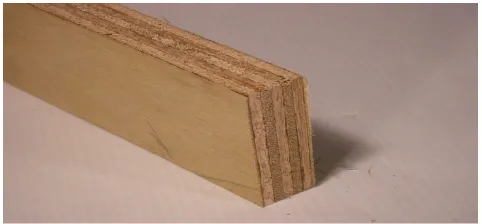
[image:1.595.312.553.628.740.2]2. Basic Components of the Project
Description of above base of robotic arm ● Material:- Plywood
● Length:- 40 cm ● Breadth:- 28 cm ● Thickness:- 2 cm
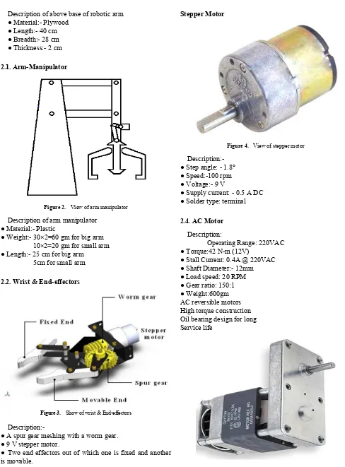
2.1. Arm-Manipulator
Figure 2. View of arm manipulator Description of arm manipulator
● Material:- Plastic
● Weight:- 30×2=60 gm for big arm 10×2=20 gm for small arm ● Length:- 25 cm for big arm
5cm for small arm
2.2. Wrist & End-effectors
Figure 3. Show of wrist & End-effectors
Description:-
● A spur gear meshing with a worm gear. ● 9 V stepper motor.
● Two end effectors out of which one is fixed and another is movable.
2.3. Motors (Stepper and AC motor)
[image:2.595.56.544.63.724.2]Stepper Motor
Figure 4. View of stepper motor
Description:- ● Step angle: - 1.8° ● Speed:-100 rpm ● Voltage:- 9 V
● Supply current: - 0.5 A DC ● Solder type: terminal
2.4. AC Motor Description:
Operating Range: 220VAC ● Torque:42N-m (12V)
● Stall Current: 0.4A @ 220VAC ● Shaft Diameter:- 12mm ● Load speed: 20 RPM ● Gear ratio: 150:1 ● Weight:600gm AC reversible motors High torque construction Oil bearing design for long Service life
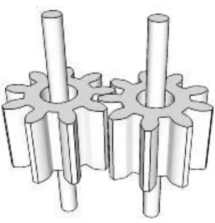
[image:2.595.334.533.93.255.2]Figure 6. View of spur gear arrangement
Description:-
● No of teeth on pinion=24 ● No of teeth on gear=36 ● Gear ratio= 36/24 =3/2
● Diameter of gear and pinion= 25mm and 15 mm respectively.
● Pressure angle= 20°
● Module=1.75 mm
● Pitch line velocity =πDpNp/60=(π*0.015*20)/60=0.015 m/s
2.6. Shaft and Bearing Arrangement
Figure 7. View of Shaft and bearing arrangement Description:-
● Material:- Mild Steel ● Diameter of shaft:- 15 cm ● Length of shaft:- 28 cm ● Bearing type:- Ball bearing
3. Design
3.1. Design of Gripper Links
The object to be lifted is: - Metal Plates Weight of the object: - 50-80gm The link has two parts, Part1 and Part2. The Arm manipulator has length as follows:-
Part1 = 25 cm Part2 = 5 cm
Therefore, the ratio of the length of the two links is Link1: Link2: 5: 1
3.2. Design of Shaft Length of shaft: - 24mm Torque (T):- 42 N-m
Tangential force on gear = 2T/D (D: - Diameter of gear)
= (2x42)/0.025= 3360 N
Twisting moment (Te) =47.18 N-m
Normal load acting on tooth on gear: - Ft/cos20 = (3360/0.937)
= 3585 N
Maximum bending moment (M) = WL/4 = (3585x0.025)/4
=21.51 N-m
3.3. Power and Torque Transmitted Voltage:- 220 V
Current:- 0.4 A Speed:- 20 rpm Power transmitted: - VI P= (220*0.4) = 88 watt
4. Calculations
Torque= (P60)/2πN = (88*60)/ (2π*20) =42 N-m
4.1. Force Calculation of Joints
This will provide a fundamental understanding of moment arm calculations for statics and dynamics. The point of doing force calculations is for motor selection. We must make sure that the motor chosen can not only support the weight of the robot arm, but also what the robot arm will carry.
Choose these parameters: weight of each linkage weight of each joint weight of object to lift length of each linkage
This particular design has just two DOF that requires lifting, and the center of mass of each linkage is assumed to be acting at half of the length.
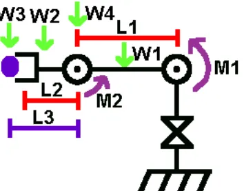
Torque about Joint 1
M1 = L1/2 * W1 + L1 * W4 + (L1 + L2/2) * W2 + (L1 + L3) * W3
Torque about Joint 2
M2 = L2/2 * W2 + L3 * W3
[image:3.595.85.266.413.549.2]Figure 8. View of loads /moments on joints
Figure 9. View of degree of freedom
Figure 10. Assembly for the Robotic Arm for Spot Welding.
6. Degree of Freedom
The degree of freedom, or DOF, is a very important term to understand. Each degree of freedom is a joint on the arm, a place where it can bend or rotate or translate. You can typically identify the number of degrees of freedom by the number of actuators on the robot arm. Now this is very important - when fabricating a robotic arm we want as few degrees of freedom allowed for our application. Because each degree requires a motor, often an encoder, and exponentially complicated algorithms and this result in increased cost
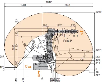
7. Robot Workspace
The robot workspace (sometimes known as reachable space) is the place where the end effector (gripper) can reach. The workspace is dependent on the DOF, angle/translation limitations, the arm link lengths, the angle at which something must be picked up at, etc. The workspace is highly dependent on the configuration of the robot.
[image:5.595.146.479.309.583.2]8. Conclusion
● This robotic technology makes the spot welding operation more flexible and time oriented.
● With the help of pick and place mechanism the material handling has been easily carried out.
● The variation in the mechanical structure and the angle of movement can be changeable.
9. Applications
● For the welding of particular types of sheet metal. ● Uses for the automobile, manufacturing industries. ● To weld straps to nickel-metal-hydride cells to make batteries.
10. Future Scope
● Mobility and navigation: future robots will be mobile, able to move under their own power and navigation systems. ● Universal gripper: robot gripper design will be more sophisticated, and universal hands capable of multiple tasks will be available.
● Systems integration and networking: robots of the future will be “user friendly” and capable of being interfaced and networked with other systems in the factory to achieve a very high level of integration.
REFERENCES
[1] Saeed B Niku, Introduction to robotics analysis,systems,appl ications,Pearson Education.Page no:- 30-68.
[2] Mikell P Groover, Industrial robotics technology,programmi ng and applications,Mc Graw Hill. Page no:-110-180
[3] S.R.Deb,Robotics technology and Flexible automation
by,Mc Graw Hill. Page no:-32-75
[4] R.K Mittal and I.J.Nagrath,Robotics & control by Tata McGrar Hills. Page no:-66-90
[5] Hajduk M., Baláž V.: Measurement deviation movement of robot Kuka from define trajectory with laser senzor ., IV mediznárodná konferencia , Mechanika z .67, Modulowe technologie i konstrukcje w budowie maszyn , Rzeszóv 2006, Polsko, str. 261-264(3).
[6] Biagiotti, L., Zanasi, R., "Online trajectory planner with constraints on velocity, acceleration and torque", Industrial Electronics (ISIE), 2010 IEEE International Symposium on, On page(s): 274 - 279
[7] C. Blume and W. Jakob Programming Languages for
Industrial Robots, 1986 :Springer-Verlag (3)
[8] I.Cox and N.Gehani "Exception handling in robotics", IEEE Computer, 1989
[9] J. J. Craig Introduction to robotics: mechanics and control, 1989 :Addison-Wesley
[10] J. Hallam "Autonomous robots: from dream to reality", Proceedings from \'Robotikdagar, 1991