International Journal of Emerging Technology and Advanced Engineering
Website: www.ijetae.com (ISSN 2250-2459, Volume 2, Issue 10, October 2012)438
Development and Control of a Prototype Hydraulic Active
Suspension System for Road Vehicles
Suresh A. Patil
1, Dr. Shridhar G. Joshi
21
Associate Professor, Dept. of Mechanical Engineering, A.D.C.E.T., Ashta, Sangli, India
2 Formerly Professor and Head, Dept. of Mechanical Engineering, Walchand College of Engineering, Sangli, India
Abstract— This paper describes a prototype Hydraulic Active Suspension System for Road Vehicles, with an objective to analyse the feasibility and effectiveness of the proposed approach. The physical system, which models a quarter-car suspension, consists of a wheel, coil springs, a Hydraulic Actuator for active damping, position, and velocity sensors, and an Direct Current (dc) motor for simulating road disturbance input signal. Here, Compared to the pneumatic actuator, hydraulic actuator has been considered as one of the most viable choices for an active suspension due to their high power-to-weight ratio and low cost. MATLAB Simulink environment (MathWorks, Inc., USA) was employed to validate the results. The results show considerable improvement in ride comfort over the conventional passive system. The details of the design construction, modeling, analysis, computer simulation, and experimental results are presented.
Keywords—Active Suspension, Ride comfort, Hydraulic
actuator, Vehicle Vibration Analysis, FFT Analyser, MATLAB SIMULINK Modelling.
I. INTRODUCTION
As with the globalised world, it is no more a wonder for a person to travel Pune to Mumbai daily for his routine duties. This might be the reason people are not only satisfied to own a car, but also dreaming of a ‘Palace on the Wheel’ kind of delight as they are spending considerable time in travelling. This fact has stimulated the developers of a road vehicle to provide genuine attention towards the state-of-the-art provision of ride comfort in their passenger vehicles. Looking at this potential demand, the authors feel it appropriate to demonstrate a study of prototype Quarter Car Hydraulic Active Suspension Analysis using MATLAB-SIMULINK environment and its validation by experimental analysis using a laboratory scaled quarter car suspension test rig.
The advent in the electronic instrumentation and state-of-the-art data acquisition systems along with their reliability and affordability has motivating the automotive industries to focus and invest on the development of an active suspension system which is capable to fulfil the need of achieving the golden mean between two conflicting optimising parameters; i.e., ride comfort and road handling.
Though theoretical research has initiated long back, the practical automotive suspension systems have been developed over the last 100 years to a very high level of sophistication. These researchers have suggested three classes of suspension systems. The passive suspension system is conventional one which involves the mechanical spring and damper with specific stiffness and damping coefficient.
Fig. 1: Conflict in ride and handling
As there is limitation for the suspension travel, the less is the scope for the performance improvement for passive suspension system. Thus, Passive suspension design is a compromise between vehicle handling and ride comfort as depicted in fig.1.
The semi-active is the class of suspension system wherein the variable dampers of different types are employed along with conventional spring.
In active suspension system, the controlled actuators of different characteristics are included between passenger compartment and chassis.
International Journal of Emerging Technology and Advanced Engineering
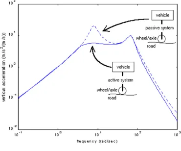
Website: www.ijetae.com (ISSN 2250-2459, Volume 2, Issue 10, October 2012) [image:2.612.73.258.229.383.2]439 With an active suspension, the force actuator can apply force independent of the relative displacement or velocity across the suspension. It is quite obvious here that if correct control strategy is facilitated, the proposed suspension results in a better compromise between ride comfort and vehicle stability as compared to a passive system, as depicted in fig. 2.
Fig.2: Strategy of betterment of Ride Comfort
II. PRESENT THEORIES AND PRACTICES
Automotive suspension systems have been researched exhaustively by many researchers from all over the continents since long and now, in the era of 21st century’s rapid technology revolution, reached to a very high level of sophistication. Some of the important contributions reported in research journals are as follows:
Sharp and Crolla [1] has described road surfaces, modeling vehicles and setting up performance criteria to passive, active and semi-active suspension systems. They also elaborated methods of deriving control laws for active systems. D.A.Crolla [2], in his review paper reviews the contributions of vehicle dynamics theory to practical vehicle design. Dean Karnopp [3] shows, using simple linear two degree-of-freedom suspension system model that even using complete state feedback, there still are limitations to suspension performance.
In the fully active case, Richard Poley [4] described the working and applications of DSP control of electro-hydraulic servo actuators for active suspension system. M. Senthikumar [5], in his work shows the development of an active suspension system using a proportional- integral- derivative (PID) controller.
M. Senthikumar, S. Vijayarangan [6], show with their experimentation that active suspension system works better than passive suspension.
Also, they have found that, at higher frequencies (1 Hz and more) the performance of active suspension system deteriorates as force tracking at higher frequencies is difficult. Ali J. Koshkouei [7] presents a method for controlling a quarter-car hydraulic active suspension system using SMC techniques.
III. MODELING OF A2DOFQUARTER CAR SUSPENSION SYSTEM
[image:2.612.394.493.344.449.2]A Typical Quarter Car Model is taken for the analysis because of its simplicity and easy implementation at institute laboratory. The model depicts the car body mass, wheel mass, springs, a passive damper, and an active damper.
Fig. 3: 2 DOF Quarter Car Suspension System Model
The figure 3 describes the scheme of a 2 DOF Hydraulic Quarter Car Suspension System
Where,
Ms = Sprung Mass (car body mass) Mu = Unsprung Mass (wheel system mass) Ks = Suspension Spring Stiffness
Ku = Tyre Spring Stiffness Cs = Damping Coefficient
x
s = Sprung Mass displacementx
u = Unsprung Mass displacement r = Road Disturbance inputThe governing differential equations of motion for the quarter car model are,
International Journal of Emerging Technology and Advanced Engineering
Website: www.ijetae.com (ISSN 2250-2459, Volume 2, Issue 10, October 2012)440
m
ü
u+ c
s(
̇
u-
̇
s) +( k
u+k
s)
u- k
s s= k
uy
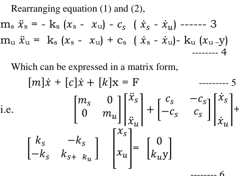
--- 2 Rearranging equation (1) and (2),
m
s̈
s= - k
s(
s-
u) -
(
̇
-
̇
) --- 3
m
ü
u= k
s(
s-
u) + c
s(
̇
s-
̇
u)- k
u(
u –y)
--- 4
Which can be expressed in a matrix form,
[ ] ̇
+
[ ] ̇
[ ]
x = F
--- 5i.e.
[
] ⌈
̈
̈
⌉ [
] ⌈
̇
̇
⌉
+
[
]
[
]
=
[
]
--- 6
[image:3.612.358.530.134.280.2]We may add a damper Cu in parallel to Ku, as shown in Figure, to model any damping in tires. However, the value of Cu for tires, compared to Cs, is very small, and hence, we have ignored Cu to simplify the model.
IV. EXPERIMENTAL ANALYSIS
The physical prototype system of 2 DOF suspension system is developed as shown in fig.4. This prototype is an assembly of a sprung mass, two linear springs, hydraulic cylinder and valving, and position and velocity sensors. A three-phase direct current (dc) motor driving a cam was included for generation of a sinusoidal road surface disturbance input. The signals from the sensors were processed by a microcontroller which controlled the hydraulic actuator.
[image:3.612.48.287.160.336.2]
Fig.4: Prototype of 2DOF Quarter Car Active Suspension
Fig. 5:D.C.Motor Cam Type Vibration Exciter
The mechanism for road disturbance input was developed with the goal of driving the suspension system in the vertical direction. It was found that a circular cam with an offset bore would produce a very good approximation of a sinusoidal waveform when driving a load placed upon its surface. The cam had 0.03m peak to peak stroke and it generated a waveform modeled as
r (t) = 0.03 sint --- 7
The cam and follower unit is used as vibrator for giving the vibrations similar to bumpy road profile to the unsprung mass plate. The cam is driven by 2 HP three phase D.C.electric motor and the follower is attached to unsprung mass plate. The given selected ranges of frequencies are provided by varying the speed of cam. The speed variation of cam directly coupled to motor shaft is achieved by speed regulation of motor by varying the voltage supply.
The sprung mass position Xs and wheel mass position Xu, shown in Fig. 3, were measured by identical accelerometers. Two identical amplifier and filter combination circuits were used to process the measured position signals.
[image:3.612.92.246.533.657.2] [image:3.612.352.536.553.683.2]International Journal of Emerging Technology and Advanced Engineering
Website: www.ijetae.com (ISSN 2250-2459, Volume 2, Issue 10, October 2012)441
[image:4.612.95.243.134.269.2]FIG.7:Voltage Regulator forFrequencyVariation
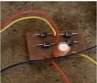
Fig. 8 Rectifier to convert A.C. to D.C.
V. EXPERIMENTAL RESULTS
Following parametric data is used for experimental analysis as well as for simulation analysis
TABLE 1
Test Rig Suspension Model Parameters
[image:4.612.325.559.183.311.2]The performance analysis, of the experimentation on the 2 DOF Quarter Car Test Rig, is carried out by employing state-of-the-art 4 Channel ADASH FFT Analyser alongwith DDS 2011 Data Acquisition and Interpretation platform.
[image:4.612.91.256.297.439.2]Fig. 9: Unsprung Mass Displacement Response in Experimental Analysis
Fig. 10: Sprung Mass Displacement Response in an Experimental Analysis
Fig. 11: Unsprung Mass Velocity Response in an Experimental Analysis
Critical Parameter Parametric Characteristics
Sprung mass 8 kg
Unsprung mass 1.5 kg
Suspension spring stiffness
7000 N/m
Suspension damping coefficient
275 Ns/m
[image:4.612.328.558.349.484.2] [image:4.612.323.566.508.615.2] [image:4.612.60.282.535.672.2]International Journal of Emerging Technology and Advanced Engineering
Website: www.ijetae.com (ISSN 2250-2459, Volume 2, Issue 10, October 2012) [image:5.612.324.563.122.300.2]442
[image:5.612.48.287.125.247.2]Fig. 12: Sprung Mass Velocity Response in an Experimental Analysis
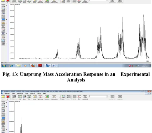
[image:5.612.320.560.151.635.2]Fig. 13: Unsprung Mass Acceleration Response in an Experimental Analysis
Fig. 14: Sprung Mass Acceleration Response in an Experimental Analysis
VI. SIMULATION ANALYSIS
Simulation analysis is carried out in MATLAB SIMULNK R 2010 Environment by modelling the quarter car system.
Fig. 15: MATLAB Simulink Model of 2DOF Suspension System
Fig.16: Input Signal for MATLAB Analysis
[image:5.612.46.290.274.392.2] [image:5.612.47.289.283.496.2] [image:5.612.326.562.333.527.2]International Journal of Emerging Technology and Advanced Engineering
Website: www.ijetae.com (ISSN 2250-2459, Volume 2, Issue 10, October 2012)443
[image:6.612.51.286.135.278.2]Fig. 18: Sprung Mass Displacement in MATLAB Analysis
Fig. 19: Unsprung Mass Velocity in MATLAB Analysis
VII. RESULTS AND DISCUSSIONS
By analysing the Hydraulic Quarter Car Suspension approach, it is found that both analysis tools; experimental and simulation; have shown decent improvement in ride parameters as depicted below. The values of active suspension parameters are seen reduced substantially, over a range of excitation frequencies near the region of resonance.
TABLE 2 Result Table
Masses Concerned Parameter
Passive system(Mat lab)
Active system ( Matlab)
Active system ( Expt.) Unsprun
g mass
Displacement(m) 1.450*10-5 1.430*10-5 0.5294*1
0-6
Sprung mass
Displacement(m) 1.350*10-5 0.900*10-5 0.1609*1
0-6
Unsprun g mass
Velocity (m/s) 1.620*10-3
0.80*10-3 0.80*10-3
Sprung mass
Velocity (m/s) 0.880*10-4 0.43*10-4 0.54*10-4
Unsprun g Mass
Acceleration( m/s2)
11.3*10-5 11.0*10-5 14.1*10-5
Sprung Mass
Acceleration( m/s2)
4.9 *10-5 3.2 *10-6 4.0*10-6
Thus by implementation of Hydraulic Active Suspension, the ride comfort of the occupants is improved to a reasonable degree; provided one should get acquainted with the complexity of the hydraulics.
REFERENCES
[1 ] R. S. Sharp, D.A. Crolla, Road vehicle suspension system design- a review, vehicle system dynamics 16(1987) 167-192.
[2 ] D.A. Crolla, Vehicle dynamics- theory into practice, proceedings of institution of engineers, 210 (1996) 83-94.
[3 ] Dean Karnopp, Theoretical limitations in active vehicle suspensions, vehicle system dynamics, 15 (1986) 41-54.
[4 ] Richard Poley, Electro-hydraulic servo actuators, DSP field applications, Texas Instruments, SPRAA 76, January 2005. [5 ] M. Senthikumar, Development of active suspension system for
automobiles using PID controllers, proceedings of the world congress on engineering (2008) Vol. II, London, U.K.
[6 ] M. Senthikumar, S. Vijayarangan, Analytical and experimental studies on active suspension system of light passenger vehicle to improve ride comfort, Mechanika (2007) 34-41.
[image:6.612.51.288.303.423.2]