International Journal of Emerging Technology and Advanced Engineering
Website: www.ijetae.com (ISSN 2250-2459, Volume 2, Issue 5, May 2012)50
FlexRay™ Protocol based an Automotive Application
Avinash K R
1, P Nagaraju
2, Surendra S
3, Shivaprasad S
41,2 Dept. of Telecommunication, R.V. College of Engineering, Bangalore, India 3,4 IFIN VV, Infineon Technologies India Pvt. Ltd, Bangalore, India
Abstract— FlexRay™ protocol is developed to meet the
demand of the next generation high capacity in-vehicle data communication. It is the high speed, deterministic, fault-tolerant and flexible protocol. There are large number of Electronic Control Units (ECUs) used in a high end automobile like car. Safety critical and high speed applications require such a protocol for enabling ECUs to communicate efficiently. In this work, we used Infineon SoCs as FlexRay™ nodes and establish communication between multiple nodes using FlexRay™ protocol. A simple automotive application is developed with temperature and magnetic field sensor being connected to a node and the sensor data is being communicated over the FlexRay™ network. Here, single code is written is for both coldstart nodes and non-coldstart nodes.
Keywords—FlexRay™ protocol; Automobile; Data communication; ECU; Multiple nodes; Infineon SoC.
I. INTRODUCTION
Nowadays, automotive electronic systems are complex distributed embedded systems which are composed of several electronic control units (ECUs) (called as Nodes) interconnected by a communication network [1].More the ECUs, more complex the network. With the rapid development of automobiles and the subsequent development in the in-vehicle applications, the demand for high speed in-vehicle data communication increased well beyond the capacity of existing automotive network. For non-safety-critical communication, a number of protocols have become popular, such as LIN, CAN, MOST, Bluetooth, and ZigBee. For safety-critical and more complex applications, several communication protocols have been introduced such as Byteflight, TTP/C, TT-CAN, and FlexRay™ [1]. FlexRay™ protocol is advancing as the predominant protocol. It has lots of advantages in terms of the bandwidth, the type of message transmission and fault tolerant mechanism etc., it is likely to become the de-facto industry standard for X-by-wire and other safety-critical applications [1-3].
FlexRay™ protocol was originally developed by FlexRay™ Consortium formed in the year 2000 by BMW and DaimlerChrysler.
The consortium has grown to include the automotive industry‟s largest and most influential players [1], [4-5]. The FlexRay™ development is driven by the core partner companies, BMW, DaimlerChrysler, Freescale Semiconductor, GM, NXP Semiconductors, Robert Bosch and Volkswagen [1], [4], [6]. The number of members and development partners had grown to almost 150 [1]. After the completion of the development of the protocol, the Consortium disbanded in the year 2009 [5].
II. FLEXRAY™PROTOCOL
FlexRay™ is a scalable, flexible, high-speed, deterministic, error-tolerant communication technology that is designed to meet growing safety related challenges in the automobile industry [4]. Mainly, this technology is concentrated for data communication in very safety critical use areas in automobile [4]. A FlexRay™ communication system is made up of a number of FlexRay™ nodes and a physical transmission medium (FlexRay™ Bus) interconnecting all of the FlexRay™ nodes. FlexRay™ node is an Electronic Control Unit (ECU) which is connected to a FlexRay™ bus via a FlexRay™ interface [6]. FlexRay™ interface is made up of communication controller and one or two bus drivers depending on the number of channels. Basically there are two channels available. System designer can choose between single channel or dual channel configuration [6].
The FlexRay™ protocol is a unique time-triggered protocol [1-3], [7], that provides options for deterministic data that arrives in a predictable time frame (down to the microsecond) as well as CAN-like dynamic event-driven [1-3], [7], data to handle a large variety of frames. FlexRay™ accomplishes this hybrid of core static frames and dynamic frames with a pre-set communication cycle that provides a pre-defined space for static and dynamic data [7]. The main physical topologies are bus, star and ring [6]. The hybrid topology of the mentioned basic topologies is also possible.
International Journal of Emerging Technology and Advanced Engineering
Website: www.ijetae.com (ISSN 2250-2459, Volume 2, Issue 5, May 2012)51 Every FlexRay™ node is synchronized to the same clock, and each node waits for its turn to write on the bus. Because the timing is consistent in a TDMA scheme, FlexRay™ is able to guarantee determinism [1], [4] or the consistency of data deliver to nodes on the network. This provides many advantages for systems that depend on up-to-date data between nodes. The communication cycle, which is periodically repeated, is composed of static and dynamic segments, symbol window and NIT (network idle time). Within the static segment the TDMA (time division multiple access) method is used. This segment is usually designed for the high priority frames with the same length of payload. It is divided into static slots where each node can transmit its own frame. Several static slots can be assigned to one node, but each of these static slots may be used just by one node. The FlexRay dynamic segment is intended for the non-critical and sporadic messages with variable length. An access to the bus is based on the flexible TDMA. In the symbol window the CAS (Collision Avoidance Symbol), MTS (Media Access Test Symbol) or WUS (Wake Up Symbol) can be sent [8]. The WUS serves only for wakeup of the cluster. The CAS is used by a coldstart node (the node, which is configured for setup of the cluster) to initialize the start-up procedure. During the last part of the communication cycle (i.e. network idle time), each node can correct the offset of its own time base. For a cluster assembly at least two nodes are necessary. The start-up is performed on all channels synchronously [8]. The initialization of the startup process is called coldstart. In the case that there is no activity on a bus (before the startup procedure) one of the nodes can wake up a cluster. The minimum prerequisite for a cluster wakeup is that the receivers of all bus drivers are supplied with power. A bus driver has the ability to wake up the other components of its node when it receives a wakeup pattern (WUS) on its channel [7]. The wakeup pattern may not be transmitted on both channels at the same time. This prevents a faulty node from disturbing communication on both channels simultaneously with the transmission. Further detailed information about e.g. time synchronization procedure can be found in protocol specification- [7].
III. APPLICATION
The automobiles like cars usually implement a sensor network to display the characteristics of the environment like temperature, rainfall, magnetic field etc. The application being developed considered such a sensor which senses the temperature and magnetic field near it.
The nodes at various places within an automobile would be requiring characteristics of the environment for various reasons like automatic closing of window of the car, informing the user of the car when a severe temperature is observed etc. To implement that in this work, the sensor data is being communicated to the coldstart node using FlexRay™ protocol. This is achieved by connecting the sensor to a non-coldstart node The sensor module in the node receives the data from the sensor. The sensor data is then communicated to the coldstart node using FlexRay™ protocol. As an extension of this application, one can use the sensor data at a coldstart node to develop a real time scenario of an automobile. Here, even though there is no master slave concept, if we could consider the coldstart nodes as the masters and the non-coldstart nodes as slaves, then communicating the sensor data from the non-coldstart node to the coldstart node exhibits real scenario where in slave updating the data to the master. This is an extended work of – [9] and [10]. Here, single code is written for both coldstart and non-coldstart nodes.
IV. IMPLEMENTATION
[image:2.612.343.535.438.599.2]As mentioned in the abstract, we used Infineon SoC as an ECU (Node) which includes FlexRay™ Communication Controller (CC) and Sensor module is as shown in the Fig.1
Figure 1.Electronic Control Unit ( Node)
Some of the specifications considered are: (parameters meaning can be found in [7])
1. Number of nodes in the cluster = 4 2. Data rate =10Mbps
3. Number of channels = 2 ( Coldstart nodes) and 1 ( Non- Coldstart nodes)
4. Physical Medium = Flexible Ribbon Cable 5. Duration of one cycle = 1ms
International Journal of Emerging Technology and Advanced Engineering
Website: www.ijetae.com (ISSN 2250-2459, Volume 2, Issue 5, May 2012)52 7. Number of sync nodes maximum in a cluster :
gSyncnodeMax = 4
8. Number of non-coldstart nodes = 2
9. Number of Macroticks / cycle : gMacroPerCycle = 1000d
10. Macrotick Initial Offset :
gMacroInitialOffset[A] = gMacroInitialOffset[B] = Ah(MT)
11. Microtick Initial Offset : pMicroInitialOffset[A] = pMicroInitialOffset[B] = 25d(μT)
12. Offset Correction Start : gOffsetCorrectionStart = 915d (MT)
13. Network Idle time: gNIT =910d (MT)
14. Delay compensation channel A : pDelayCompensation[A] = 4d(μT)
15. Delay compensation channel B : pDelayCompensation[B] = 4d(μT)
16. Cluster drift damping : pClusterDriftDamping = 1(μT)
17. Decoding Correction :pDecodingCorrection = 52d(μT)
18. Accepted startup range :
pdAcceptedStartupRange = 129d(μT)
19. Maximum oscillator drift : pdMaxDrift = 49d(μT) 20. Static slot length : gdStaticSlot = 50d (MT) 21. Number of Static slots : gNumberOfStaticSlots =
10d
22. Minislot length : gdMinislot = 4 (MT)
23. Number of Minislots : gNumberOfMinislots = 100d
24. Dynamic slot Idle phase
:gdDynamicSlotIdlePhase = 1minislot
25. Minislot Action Point :
gdMinislotActionPointOffset = 3 ( MT) 26. Action Point offset = 8 (MT)
27. Maximum offset correction :
pOffsetCorrectionOut = 206d(μT)
28. Maximum rate correction : pRateCorrectionOut = 169d(μT)
29. External offset correction control : pExternOffsetControl = No
30. External offset correction : pExternOffsetCorrection = 7(μT)
31. External rate correction : pExternRateCorrection = 7(μT)
32. Transmission Start Sequence Transmitter : gdTSSTransmitter = 8bit duration ( 1 bit = 4 μT = 100ns)
33. Collision Avoidance Symbol Maximum : gdCASRxLowMax = 99d bit times
34. gdSampleClockPeriod = 12.5 ns
35. Number of samples per Microtick : gSamplesPerMicrotick = 2
36. Wake up Symbol Receive Window length : gdWakeupSymbolrxWindow = 76d bit times 37. Repetitions of Transmission of wake up pattern :
pWakeupPattern = 2
38. Wake up Symbol Receive Idle : gdWakeupSymbolRxIdle : 18d bit times
39. Wake up Symbol Receive Low : gdWakeupSymbolRxLow = 18d bit times
40. Wake up Symbol Transmit Idle : gdWakeupSymbolTxIdle = 180d bit times
41. Wake up Symbol Transmit Low : gdWakeupSymbolTxLow = 60d bit times
42. Static Frame data length : gPayloadLengthStatic = 4( = 4*2 = 8bytes)
43. Start of Latest Transmit : pLatestTx = 63d minislots
44. Listen Time out : pdListenTimeout = 272E2 h (μT)
45. Listen Time out Noise : gListenNoise-1 = Fh 46. Maximum Without Clock correction passive :
gMaxWithoutClockCorrectionPassive = Eh 47. Network Management Vector Length :
gNetworkManagementVectorLength = 8bytes 48. pKeySlotUsedForStartUp = yes
49. pKeySlotUsedForSync = yes
50. Number of Coldstart attempts : gColdStartAttempts = 31d
51. Passive to Active : pAllowPassiveToActive = 07 Where d = decimal ; MT = Macrotick; μT = Microtick
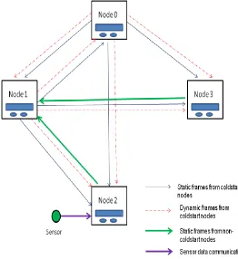
A. Scenario considered
International Journal of Emerging Technology and Advanced Engineering
Website: www.ijetae.com (ISSN 2250-2459, Volume 2, Issue 5, May 2012)53
Figure 2. Nodes connected respective channel(s)
TABLE 1
TRANSMISSION AND RECEPTION SCHEDULE OF NODES
Node Frame Mode Slot Buf Cycle
Node 0 Sync tx 3 0 0
Node 0 Dyn tx 13 5 0
Node 1 Sync tx 4 0 0
Node 1 Dyn tx 15 6 0
Node 1 Dyn tx 16 7 0x46
Node 2 Static tx 8 2 0x42
Node 3 Static tx 7 3 0
Node 0 Sync rx 4 1 0
Node 0 Dyn rx 15 6 0
Node 0 Dyn rx 16 7 0x46
Node 1 Sync rx 3 1 0
Node 1 Dyn rx 13 5 0
Node 1 Static rx 8 2 0x42
Node 1 Static rx 7 3 0
Node 2 Sync rx 3 1 0
Node 2 Sync rx 4 4 0
Node 2 Dyn rx 13 5 0
Node 2 Dyn rx 16 7 0x46
Node 3 Sync rx 3 1 0
Node 3 Sync rx 4 4 0
Node 3 Dyn rx 13 5 0
Node 3 Dyn rx 15 6 0
V. ALGORITHM OF THE CODE
Step 1. Begin
Step 2. Program to Protocol Config state
Step 3. Configure the System and Peripheral Clock for FlexRay™ module
Step 4. Initialization of Interrupts for FlexRay™ module Step 5. Initialization of Ports for FlexRay™ module
Step 6. Configure the Peripheral Clock for the sensor module
Step 7. Initialization of Interrupts for Sensor module
Step 8. Initialization of Ports for Sensor Module
Step 9. Initialize the node to node „arbitrary‟ ( to receive sync frames from node 0 and node 1 and static frame node 2 ,if any in the cluster)
Step 10. Check whether the sync frames from Node 0 or Node 1 are received (Assuming Cluster communication already started)
If No? Goto Step 11. If Yes ? Goto Step 12
Step 11. Check whether the wait for sync frames is over
If NO? Goto step 10 If Yes ? Goto Step 13
Step 12. Check whether Node 2 data available
If No? Goto Step 18 If Yes? Goto Step 19
Step 13. Initialize the Node to Node 0 Schedule:
International Journal of Emerging Technology and Advanced Engineering
Website: www.ijetae.com (ISSN 2250-2459, Volume 2, Issue 5, May 2012)54 Step 14. Allow Node to Coldstart for the start up of the
cluster
Step 15. Check whether the node is Normal Active If No? Goto Step 16 If Yes? Goto Step 22
Step 16. Check whether CAS is received?
If No? Goto Step 15 If Yes? Goto Step 17
Step 17. Initialize the Node to Node 1 Schedule:
Configure the parameters, Baud rate, Static and Dynamic buffers, Transmission and Reception Schedule etc.
Goto Step 15.
Step 18. Check whether the wait for Node 2 data is over ?
If No? Goto Step 12 If Yes? Goto Step 20
Step 19. Initialize the Node to Node 3 Schedule:
Configure the parameters, Baud rate, Static and Dynamic buffers, Transmission and Reception Schedule etc .
Goto Step 21
Step 20. Initialize the Node to Node 2 Schedule:
Configure the parameters, Baud rate, Static and Dynamic buffers, Transmission and Reception Schedule etc
Step 21. Check whether the Node is in Normal Active ?
If No? Goto Step 21
If Yes? Goto Step 22
Step 22. Get input from the user
Display the temperature, magnetic field and the
Range of the Sensor.
Step 23. Display no. of times various interrupts occurred.
Step 24. End
Once the Cluster communication gets established by the coldstart nodes, interrupts occurred as the new data reception and transmission occurs. Node 0, Node 1, Node 2 and Node 3 nodes experienced interrupts according to their transmission and reception schedule. The interrupts are serviced in the interrupt routine for the respective interrupts.
VI. RESULT ANALYSIS
Fig.3 gives the overview of actual communication taking place between the nodes.
Summary of the application:
1. Cluster communication initiation was successful by exchanging startup frames and synchronization was established by using the data present in startup frames. Interrupts generated indicated the correct transmission and reception of frames between node 0 and node 1.
[image:5.612.323.585.371.657.2]2. The non-coldstart node then joined the cluster. The new node in the cluster initialized to node arbitrary schedule and collected sync frames from node 0 and node 1. This node is only connected to channel A. This node then waited for the frames from node 2 if existed. When this was not successful, this node was initialized to node 2.
International Journal of Emerging Technology and Advanced Engineering
Website: www.ijetae.com (ISSN 2250-2459, Volume 2, Issue 5, May 2012)55 3. Successful transmission and reception of frames
between the node 0, node 1 and node 2 is observed through interrupts.
4. Switching off the node 2 did not affect the transmission and reception of frames between the node 0 and node 1.
5. The non-coldstart node then joined the cluster. This new node in the cluster initialized to node arbitrary schedule and collected sync frames from node 0 and node 1. This node is only connected to channel A. This node then waited for the frames from node 2 if existed. When this was successful, this node was initialized to node 3.
6. Successful transmission and reception of frames between the node 0, node 1, node 2 and node 3 is observed through interrupts.
7. Switching off the node 2 did not affect the transmission and reception of frames between the node 0, node 1 and node 3.Adding another new node to the cluster when node 2 was switched off, joined the cluster being node 2.
8. Similarly, switching off the node 3 did not affect the transmission and reception of frames between the node 0, node 1 and node 2.Adding another new node to the cluster when node 3 was switched off, joined the cluster being node 3.
9. Sensor connected to node 2, senses the environment continuously and sends the data to the sensor module. Upon the new data being received in the sensor module, the new data is moved into the register.
10. Upon the reception of new sensor data in the sensor module of node 2, the new data stored in the register is sent to node 1 using FlexRay™ frame.
11. Upon the user input, room temperature, magnetic field near the sensor and the range of the magnetic field of the sensor displayed at respective node i.e., node 1 and node2.
VII. CONCLUSION
FlexRay™ multinode communication is established successfully with both broadcast and node specific communication on Infineon SoCs with single code which includes code for both coldstart and non-coldstart nodes.
The sensor data being received continuously at node 2, is transmitted successfully to node 1 using FlexRay™ Protocol, which is verified by displaying the temperature and magnetic field at node 1.
VIII. FUTURE WORK
To develop an efficient safety critical real time application using FlexRay™ multinode cluster and hence evaluate its performance.
ACKNOWLEDGMENT
We would like to thank Infineon India Pvt. Ltd, Bangalore and R V. College of Engineering, Bangalore for giving us support and guidance to carry out this work successfully.
REFERENCES
[1] Yasser Sedaghat and Seyed Ghassem Miremadi, “A Low- Cost On-Line Monitoring Mechanism for the FlexRay Communication Protocol,” IEEE-Fourth Latin-American Symposium on Dependable Computing, 2009
[2] K. Schmidt and E. G. Schmidt, “Message scheduling for the FlexRay protocol: The Dynamic segment,” IEEE Trans. Veh. Technol., vol. 58, no. 5, pp. 2160–2169, Jun. 2009.
[3] K. Schmidt and E. G. Schmidt, “Message scheduling for the FlexRay protocol: The Static segment,” IEEE Trans. Veh. Technol., vol. 58, no. 5, pp. 2170–2179, Jun. 2009
[4] Yi-Nan Xu, I. G. Jang, Y. E. Kim, J. G. Chung and Sung-Chul Lee, “Implementation of FlexRay Protocol with An Automotive Application,” IEEE SoC Design Conference, 2008.
[5] [Online] http://www.flexray.com
[6] Richard Murphy, “A CAN to FlexRay Migration Framework,” Msc. Thesis, Waterford Institute of Technology, Ireland.
[7] FlexRay Communication Protocol Specification V2.1 Rev A- FlexRay Consortium
[8] Denis Waraus, “Steer-by-wire system based on FlexRay protocol"
[9] Avinash K R, P Nagaraju, Surendra S, Shivaprasad S,” Communication between Multiple Nodes Using FlexRay™ Protocol”, Proc.International Conference on Electronics and Communication Engineering(ICECE 2012), Chennai,India, April 2012.