2017 2nd International Conference on Computational Modeling, Simulation and Applied Mathematics (CMSAM 2017) ISBN: 978-1-60595-499-8
Study on Performance of Dynamic Pressure Type
Lubricant-Air Separator Based on Population Balance Model
Xiao-bin ZHANG
*, Wei-bing ZHU and Lei QIAN
College of Aerospace and Civil Engineering, Harbin Engineering University, Harbin 150001, China
*Corresponding author
Keywords: Dynamic pressure type lubricant-air separator, Population balance model, Separation performance.
Abstract. In order to investigate the flow characteristics and separation performance of oil-gas two-phase flow of dynamic pressure type lubricant-air separator, the influence of the structure form, temperature and inlet oil-gas ratio on the separation performance was studied based on the population balance model (PBM). The results show that, the combination of the built-in air outlet pipe and the tangential oil outlet pipe can improve the separation performance of the separator; when the oil flow rate is 6L/min and the temperature range is 100-250°C, the separation performance of the separator is improved with the increase of temperature; when the gas flow rate is 6L/min, the increase of the oil-gas ratio will cause the swirl intensity in the separator to be strengthened, and the separation performance of the separator will be improved.
Introduction
As the process of lubrication, oil will be mixed with air to form an emulsion, the specific heat and thermal conductivity of the two-phase mixture decrease, this will reduce the performance of heat exchanger, increase the flow resistance, deteriorate the cooling and lubrication conditions of the surface. Because of the simple structure, the dynamic pressure type lubricant-air separator is often used as the only main separator in some missile engine, the separation efficiency will directly affect the performance of the engine.
There are few studies on dynamic pressure type lubricant-air separators in the field of aviation, the separation device with the same working principle is mainly used in the field of petroleum industry, called cyclone or axial flow separator[1]. The experimental method, numerical simulation and theoretical method are used to research the separator[2-10].
In order to study the gas-liquid two-phase flow characteristics and separation performance of dynamic pressure type lubricant-air separator (hereinafter referred to as separator), and consider the effect of breakup and coalescence behavior caused by collision between bubbles on the separation performance, the method of coupling PBM and CFD two-fluid model is used in this paper. First, the accuracy of the method is verified by comparing with the experimental results, and then the influence of different factors on the separation performance is studied.
Model Verification and Numerical Simulation
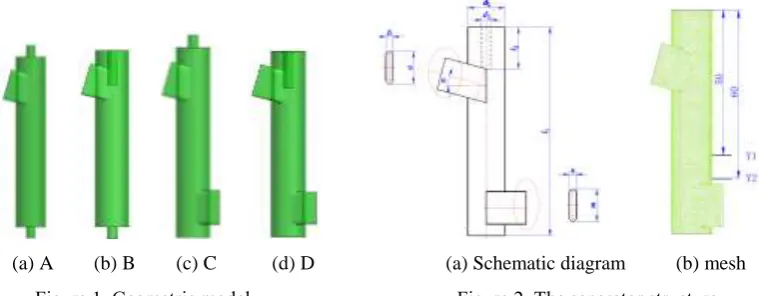
Geometric Model and Mesh
[image:2.595.108.488.74.222.2]
(a) A (b) B (c) C (d) D (a) Schematic diagram (b) mesh
[image:2.595.114.250.439.560.2]Figure 1. Geometric model. Figure 2. The separator structure.
Table 1. Structural parameters of 4 kinds of separators.
A B C D
l1 /(mm) 76 76 76 76
d1 /(mm) 13 13 13 13
l2 /(mm) 15 15 15 15
d2 /(mm) 4 4 4 4
α 15° 15° 15° 15°
a/b /(mm) 14/3 14/3 14/3 14/3
d3(length m/ width n)/(mm) 4 4 14/3 14/3
Algorithm Verification
In order to evaluate the accuracy of the results obtained from the PBM model in the unsteady state, the numerical calculation and experiment are carried out with the same separator, D. Under the same conditions, the calculated results are compared with the experimental results, as shown in Figure 3.
Figure 3. Comparison of calculated and experimental data. Figure 4. Effect of structure on void fraction.
It can be seen that the experimental value of each flow is lower than the calculated value. This paper argues that, during the experiment, there is a large amount of gas in the oil pipe, the sample is a mixture of oil. The experimental results represent the void fraction in the oil, but the calculation results represent the gas volume of the whole section, so the experimental value is less than the calculated value. It can be seen that the numerical calculation is consistent with the experimental results of the variation trend of void fraction. It can be concluded that the coupling of PBM and the two-fluid model can be used to study the separation performance of the separator.
Numerical Results and Analysis
Effect of Structure on Separation Performance
[image:2.595.349.480.439.559.2]can improve the separation performance of separator. The oil outlet void fraction of structure A (B) is higher than that of C (D), which illustrates that the tangential oil outlet pipe can improve the separation performance of separator. Meanwhile, the oil outlet void fraction of structure D is significantly lower than that of the other three, and the change of oil outlet void fraction is smaller in the range of working conditions, which illustrates the separator with D structure can improve the separation performance of the separator to a great extent and it can work stably in a certain working condition.
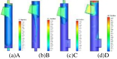
In order to study the influence of the structure on the flow field in the separator, the gas distributions of the separator with different structures when the inlet flow is 6L/min are given, as shown in Figure 5.
(a)A (b)B (c)C (d)D
Figure 5. Gas distribution in different structures.
As can be seen from Figure 5, under the same conditions, the gas distribution in different separators is very different. The gas in the A separator occupies most of the interior space, and the volume of the gas inside the B separator has a large reduction, which illustrates that the built in air outlet pipe can effectively reduce the internal gas volume. The results of C and D structure are the same. The B and D structure separators are compared and found that the B separator has a long narrow gas core, the tail of the gas core is close to the oil outlet of the separator. It is obvious that the length of B gas core can be reduced greatly after the oil outlet pipe is changed into tangential form, only part of the gas is concentrated in the top of the separator and near the gas outlet pipe, indicating that the tangential oil outlet can effectively discharge gas. The results of A and C structure are the same.
Figure 6 shows the axial velocity distribution of different sections of the four separators. In the case of Figure 6(a), the velocity of each point on the Y1 section of the A separator is greater than that of B, and the results of C and D structure are the same. It is analyzed that the different forms of the air outlet pipe will cause different internal flow resistance. Structure A(C) uses the external air outlet pipe, while structure B(D) uses the internal, indicating that the built in air outlet pipe will increase the resistance, resulting in the decrease of internal axial velocity. Comparing A(B) with C(D), the axial velocity of C(D) decreases, which indicates that the tangential oil outlet pipe will increase the flow resistance and decrease the axial velocity. The same law can also be found in Figure 6(b).
[image:3.595.202.394.213.310.2]
(a)Y1 section (b)Y2 section (a)Y1 section (b)Y2 section
Figure 6. Axial velocity distribution of different sections. Figure 7. Tangential velocity distribution of different sections.
Figure 7 is the tangential velocity distribution curve of different sections of four kinds of separators. It can be seen that the difference of tangential velocity between four kinds of separators is small, which indicates the influence of the outlet structure on the tangential velocity is not obvious. The reason may be that the fluid rotates in the separator, and the tangential velocity is mainly affected by the inlet velocity and the wall friction coefficient of separator.
[image:3.595.66.541.467.676.2]built in air outlet pipe and the tangential oil outlet pipe can greatly improve the separation performance of the separator. The following studies are based on the D structure separator.
Effect of Temperature on Separation Performance
The change of the viscosity of the oil will affect the resistance of the oil in the separator, which will affect the flow field distribution of the separator and then affect the separation performance of the separator. Because the working temperature of the dynamic pressure type lubricant-air separator is about 200℃, 4 temperature points are selected for numerical simulation in this paper.
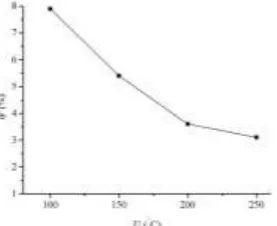
[image:4.595.231.370.280.393.2]Figure 8 shows the curve of the void fraction of the separator with oil temperature when the oil inlet flow rate is 6L/min. It can be seen that with the increase of oil temperature, oil outlet void fraction gradually decreased; when the temperature rises to 250°C, the void fraction is the lowest. At the same time, when the temperature rises to 200°C, continuing to increase the oil temperature, the change rate of oil outlet void fraction is small, indicating that increasing oil temperature can not always keep the oil outlet void fraction to maintain a substantial decline.
Figure 8. Effect of oil temperature on void fraction.
Figure 9 shows the axial velocity distribution of different cross-sections at different temperatures. It can be seen that the distribution law of axial velocity is similar at different temperatures. The speed is upward in the central region and downward near the wall. When T=100°C, the velocity values at each point of the curve are smaller than other curves. This is because when the temperature is lower, the viscosity of the lubricating oil is higher, so the resistance of the fluid is larger, and the axial velocity is smaller. With the increase of temperature, the flow resistance decreases and the axial velocity increases gradually. When the temperature increases to 250°C, the velocity values at each point of the curve are greater than those at other temperatures. Figure 10 shows the tangential velocity distribution of each section at different temperatures. It can be seen that the change of tangential velocity curve at each temperature is similar. The temperature has little influence on the tangential velocity near the center of the separator. The tangential velocity reaches peak value near the wall. The peak value of tangential velocity reached the maximum at 250°C, minimum at 100°C. It can be concluded that when the temperature increases, the viscosity of the lubricating oil decreases, and the flow resistance of the separator decreases, thus causing the tangential velocity near the wall of the separator to become larger.
[image:4.595.66.536.634.731.2]
(a)Y1 section (b)Y2 section (a)Y1 section (b)Y2 section
Figure 9. The axial velocity at different temperatures. Figure 10. The tangential velocity at different temperatures.
temperature variation discussed in this paper, the higher the temperature, the better the separation performance.
Influence of Inlet Oil-gas Ratio on Separation Performance
In order to study the influence of the oil-gas ratio on the separation performance of separator, 4 numerical simulation models are selected. The gas flow rate remains unchanged and only the oil flow rate is changed. The oil-gas ratio, a, is separately 0.5,1,2,3.
[image:5.595.220.379.258.380.2]Figure 11 shows the curve of void fraction with the oil-gas ratio at the oil outlet of the separator. It can be seen that with the increase of the oil-gas ratio, void fraction at oil outlet decreased gradually. When the oil-gas ratio is 0.5, void fraction at oil outlet is higher. With the increase of the oil-gas ratio, void fraction at oil outlet gradually decreases. At the same time, it can be seen that the variation range of void fraction at oil outlet decreases, which is due to the limited volume of the separator and the increase of the oil-gas ratio can not keep the void fraction greatly reduced.
Figure 11. The influence of the void fraction on oil outlet containing gas rate.
Figure 12 shows the axial velocity distribution of the cross section at different oil-gas ratios. It can be seen that although the oil-gas ratio is different, the axial velocity distribution of the same section is similar. The velocity of the center position varies little, which shows that the oil-gas ratio has little influence on the movement of the fluid in the center of the separator. Near the wall of the separator, the velocity varies greatly under different conditions. With the increase of the oil-gas ratio, the axial velocity increases gradually. Figure 13 shows the tangential velocity distribution of different sections of the separator under different oil-gas ratios. It can be seen that although the oil-gas ratio is different, the distribution law of tangential velocity of the same section is similar. With the increase of radius, the tangential velocity increases gradually. At the same time, the greater the oil-gas ratio, the greater the tangential velocity. It is analyzed that when the gas flow rate is constant and the oil flow rate is changed, the velocity of flow at the inlet is changed, so that the swirl intensity changes and the tangential velocity value changes.
[image:5.595.76.530.576.677.2]
(a)Y1 section (b)Y2 section (a)Y1 section (b)Y2 section
Figure 12. The axial velocity under different oil-gas ratios. Figure 13. The tangential velocity under different oil-gas ratios.
Based on the above analysis, when the gas flow rate is certain, increasing the oil flow rate can improve the separation performance of the separator. But because of the restriction of the size of the separator structure, it can only be adjusted effectively in a range.
Conclusion
(1)The numerical simulation of the separator with different structure is carried out. It is found that the combination of the built in air outlet pipe and the tangential oil outlet pipe can improve the separation performance of the separator.
(2)When the oil flow rate is 6L/min and the temperature range is 100-250°C, the flow resistance decreases gradually with the increase of temperature, and the separation performance is improved.
(3)When the gas flow rate is 6L/min, the increase of the oil-gas ratio will increase the tangential velocity of the separator, the swirl intensity is enhanced, and the separation performance of the separator is improved.
References
[1] Yu Yao. Design and Numerical Simulation of Dynamic Pressure oil-gas Separator and Centrifugal Ventilator[D]. Northeastern University, 2010.
[2] Motta B R, Erdal F M, Shirazi S A, et al. Motta B R, Erdal F M, Shirazi S A, et al. Simulation of single-phase and two-phase flow in gas-liquid cylindrical cyclone separators[Z]: ASME, 1997, 16: 1-9.
[3] Gomez L E. Dispersed Two-Phase swirling flow characterization for predicting gas Carry-under in Gas-Liquid cylindrical cyclone compact separators[D]. The University of Tulsa, 2001.
[4] Bemardo S, Moil M, Peres A P, et al. 3-D computational fluid dynamics for gas and gas-particle flows in a cyclone with different inlet section angles[J]. Powder Technology, 2006(162): 190-200.
[5] Derksen J J, Sundaresan S, Van Den Akker H A. Simulation of mass-loading effects in gas-solid cyclone separators[J]. Powder Technology, 2006(163): 59-68.
[6] Jin Xiang-Hong, Jin You-Hai, Wang Zhen-bo, et al. Experiment of geometry of gas outlet in gas-liquid cyclone separator[J]. Journal of China University of Petroleum (Edition of Natural Science), 2008(02): 108-113.
[7] Hreiz R, Gentric C, Midoux N. Numerical investigation of swirling flow in cylindrical cyclones [J]. Chemical Engineering Research and Design, 2011, 89(12): 2521-39.
[8] Hreiz R, Gentric C, Midoux N, et al. Hydrodynamics and velocity measurements in gas–liquid swirling flows in cylindrical cyclones [J]. Chemical Engineering Research and Design, 2014, 92(11): 2231-46.
[9] Zhang Xiao-Bin, Zhu Wei-Bing, Yang Chun-miao, et al. Study on performance of dynamic pressure oil-gas separator using bubble trajectory model[J]. Journal of Propulsion Technology, 2014, 35(08): 1016-1022.