Abstract—An optimal synthesis of a wideband Log-Periodic Dipole Array (LPDA) is introduced in the present study. The LPDA optimization is performed under several requirements concerning the standing wave ratio, the forward gain, the gain flatness, the front-to-back ratio and the side lobe level, over a wide frequency range. The LPDA geometry that complies with the above requirements is suitable for efficient multimedia content delivery. The optimization process is accomplished by applying a recently introduced method called Invasive Weed Optimization (IWO). The method has already been compared to other evolutionary methods and has shown superiority in solving complex non-linear problems in telecommunications and electromagnetics. In the present study, the IWO method has been chosen to optimize an LPDA for operation in the frequency range 800-3300 MHz. Due to its excellent performance, the LPDA can effectively be used for multimedia content reception over future mobile computing systems.
Index Terms—LPDA design, invasive weed optimization, optimization algorithms
I. INTRODUCTION
OBILE computing systems have been increasingly developed in recent years due to the need for high quality multimedia services. This development leads to the demand for network resources and efficient telecommunications equipment [1]-[5]. Antenna arrays play an important role in wireless communications, [6]-[10]. The radiation characteristics of an antenna array specify the operation efficiency of a communications base station in a real complex environment. Log-periodic dipole arrays (LPDAs) are special linear arrays composed of parallel dipoles of gradually increasing length as moving along the array axis from the feeding source to the end of the axis, and a pair of booms used to feed the dipoles in such a way that the feeding is inverted when passing from one dipole to the next one, [11].
Manuscript received October 13, 2014.
Zaharias D. Zaharis, Christos Skeberis, and Thomas D. Xenos are with the Department of Electrical and Computer Engineering, Aristotle University of Thessaloniki, 54124 Thessaloniki, Greece (e-mail: [email protected]; [email protected]; [email protected]).
Pavlos I. Lazaridis is with Department of Engineering and Technology, University of Huddersfield, Queensgate, Huddersfield, HD1 3DH, United Kingdom (e-mail: [email protected]).
These arrays usually demonstrate wideband behavior and low gain flatness (i.e., the difference between the maximum and the minimum forward gain values, respectively FGmax and
FGmin, over the operating bandwidth). This is due to the fact that, at every operating frequency, some of the array elements act as active dipoles while the rest of them behave as parasitic ones. Of course, these characteristics are achieved by properly selecting the geometrical parameters of the LPDA, such as the lengths and radii of the LPDA elements as well as the distances between adjacent elements.
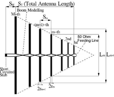
The first and also most popular procedure for LPDA design has been introduced by Carrel, [12]. This method has later been corrected by Butson and Thompson, [13], and is still used until today. The main consideration of this method is that all the LPDA elements are located inside the same angular sector (see Fig. 1). Also, the two booms, that feed the elements, are modeled as a transmission line of two conductive wires, which are inverted when passing from one element to the next one. Therefore, the whole geometry, i.e., the element lengths, radii and distances, of an M-element LPDA can be easily defined by using two special geometrical parameters, known as scale factorτ and relative spacingσ. If the desired value of the average directivity is known, the above two parameters can be calculated from the constant directivity contour curves of the well-known Carrel’s graph introduced in [12] and corrected in [13]. According to Carrel’s method, the LPDA geometry is then estimated by using the expressions given below:
, 1,...,
M m
m M
L L m M (1)
, 1,...,
M m
m M
r r m M (2)
1
2 M m , 1,..., 1
m M
S L m M (3)
where Lm and rm are respectively the length and the radius of
the m-th element, while Sm is the distance between the m-th
and the (m+1)-th element. In order to use the above three equations, the values of LM and rM (i.e., the length and the
radius of the largest element) must be known. LM is set equal
to half-wavelength at the lower operating frequency and is then reduced approximately by 5% due to the dipole thickness. The radius rM is set equal to a value that can easily
Optimal Wideband LPDA Design for Efficient
Multimedia Content Delivery over Emerging Mobile
Computing Systems
Zaharias D. Zaharis,
Member, IEEE,
Christos Skeberis, Pavlos I. Lazaridis,
Member, IEEE,
and
Thomas D. Xenos
be found in practice (e.g., 5mm).
The above design procedure is an easily applicable method. However, it is based on a rough consideration of the LPDA model and therefore it cannot estimate the exact behavior of the LPDA inside a wide bandwidth. Moreover, it generally has the ability to control the standing wave ratio (SWR), the forward gain (FG) and the front-to-back ratio (FBR). However, the method cannot control the side lobe level (SLL) as well as the gain flatness (GF) in cases of wide operating bandwidths. The need for low SLL is very critical since it helps to reduce the signal degradation due to multipath fading and also it avoids unnecessary spatial spread of radiated power. Also, a low GF value is desirable in order to keep the signal reception at similar levels over the entire operating bandwidth. It is therefore obvious, that a design method capable of controlling the values of SWR, FG, FBR, SLL and
[image:2.595.47.286.323.525.2]GF would result in an LPDA suitable for efficient content delivery. Such a method can be constructed by combing an optimization technique with a full-wave analysis of the LPDA.
Fig. 1. Carrel’s LPDA geometry.
The design method proposed here combines a recently introduced global optimization method called Invasive Weed Optimization (IWO), [14]-[17], and the Numerical Electromagnetics Code (NEC), [18], which implements a well-known full-wave analysis method called Method of Moments (MoM), [19]. Actually, the NEC calculates the radiation characteristics of the LPDA inside the operating bandwidth and returns them to the IWO method, every time this is required by the IWO in order to make fitness function calculations. To the best of the authors’ knowledge, the IWO has not been applied so far to optimize LPDAs. Unlike Carrel’s method, the proposed technique is an effective design tool that provides excellent approximation of the antenna behavior and has the ability to control all the electromagnetic characteristics mentioned above (i.e., SWR, FG, GF, FBR and
SLL) inside a wide bandwidth. Also, this study is the first effort recorded in the literature to optimize simultaneously all
these characteristics over a wide frequency range. The results shown below exhibit the superiority of the IWO-based technique over Carrel’s design method.
II. DESIGN PROBLEM DESCRIPTION
The IWO method is applied in the present study to design an optimal 12-element LPDA (M=12) for operation in the frequency range 800-3300 MHz. Specific requirements have to be satisfied: (1) SWR≤1.8, (2) FG as high as possible, (3)
GF=FGmax–FGmin ≤2dB, and (4) SLL≤–20dB on the E-plane of the radiation pattern of the LPDA. In the literature, the operating bandwidth is usually defined as the frequency range where SWR≤2 at the input of the RF system. To be sure that the LPDA will be in matching condition even in practice, the more strict value of 1.8 has been chosen in the 1st requirement. It must also be noted that, the SLL estimation takes into account all the secondary lobes on the E-plane of the radiation pattern including the back lobe. Therefore, an additional requirement that concerns the FBR is satisfied together with the 4th requirement, i.e., if the requirement for
SLL≤–20dB is satisfied then the requirement for FBR≥20dB is automatically satisfied as well.
In order to increase the degrees of freedom in comparison to Carrel’s method and thus help the IWO method to find an optimal LPDA geometry, the LPDA elements are not considered inside the same angle and therefore their lengths
Lm (m=1,...,M), radii rm (m=1,...,M) and distances Sm
(m=1,...,M–1) are independently optimized by the IWO algorithm (see Fig. 2). There are two additional optimization parameters: The first one is the distance SM between the
[image:2.595.307.546.507.712.2]largest element (M-th) and a short-circuited stub located behind this element. The second is the characteristic impedance Z0 of the line that models the booms of the LPDA. In total, there are 3M+1 variables to be optimized.
Fig. 2. Proposed LPDA geometry.
IWO-based LPDA is compared to a respective LPDA of the same total length ST derived by Carrel’s method. It must be
noted that a short-circuited stub of proper length is used by both the LPDAs (see Figs. 1 and 2), since it helps the large LPDA elements to reduce the current that may arise due to high-order resonances induced on those elements.
III. RELATED WORK ON LPDAOPTIMIZATION A deterministic design technique is not always capable of satisfying all the requirements defined by a non-linear design problem. Problems, where multiple requirements have to be met, can only be solved by applying evolutionary optimization methods. Several of these problems that concern LPDA design can be found in the literature, [20]-[29]. In some of these, a comparison between the proposed evolutionary method and other evolutionary or non-evolutionary methods is given regarding the satisfaction of the design requirements. In any case, Carrel’s method is a reference LPDA design method for comparison.
A genetic algorithm (GA), the Nelder-Mead downhill simplex method and a hybrid method that combines the above two methods are used in [20] in order to optimize LPDAs under requirements that concern the average values of FG and
SWR as well as their maximum deviation over the whole bandwidth. In [21] and [22], GAs are employed to maintain the values of FG and SWR over the entire operating bandwidth, and simultaneously minimize the LPDA length as well as the number of LPDA elements. The non-dominated sorting genetic algorithm II (NSGA-II) is applied in [23] to optimize LPDAs for operation in the range 3-30 MHz under requirements for minimum SWR, maximum FG and minimum LPDA length. A particle swarm optimization (PSO) algorithm is employed in [24] to design an optimal 10-element LPDA for operation in the range 450-1350 MHz under requirements that concern the average values of SWR, FG and FBR. In [25], an inverted-V LPDA is optimized in the range 6-30 MHz by using GAs under requirements that concern the values of
SWR, FG and SLL, as well as the LPDA size. In [26], planar LPDAs are optimized for operation in the S-band by applying a PSO algorithm under requirements that concern the values of FG and SWR. In [27], a 13-element LPDA is optimized for operation in the GSM, WiMAX, Bluetooth, Wi-Fi and 3G bands by applying PSO under requirements for the values of
FG and SWR. Also, a GA is applied in [28] to optimize a 10-element LPDA for operation in the GSM, WiMAX and Wi-Fi bands under requirements for higher FG and smaller size. Finally, the bacteria foraging algorithm is employed in [29] to optimize LPDAs for operation in the UHF TV band under requirements that concern the average values of SWR, FG,
FBR and SLL.
In all the above studies, FG and SWR are considered under optimization, except for [28] where requirements are set for high FG and small LPDA size. Requirements for low SLL
values are considered only in [25] and [29]. Nevertheless, the requirement for SLL≤–6dB in [25] is soft enough (since values
of SLL equal to –6dB are easy to be achieved) and is just defined to prevent main lobe splitting. It is also shown in [29] that the requirement for average SLL equal to –40dB is not satisfied by any of the LPDAs considered for optimization. In addition, the operating bandwidth considered in [29] is not as wide as that considered in the present optimization. In our study, practical requirements concerning the values of SWR,
FG, GF, FBR and SLL have to be satisfied inside a wide frequency range (i.e., the range 800-3300 MHz). It has to be noted that, the minimization of the LPDA length is not of our concern, since our intention is to show that the proposed design method is capable of producing an optimized geometry with better radiation characteristics than those of an LPDA geometry with the same length ST produced by Carrel’s
method.
IV.INVASIVE WEED OPTIMIZATION
Many studies are found in the literature, where evolutionary optimization techniques are applied to solve complex non-linear problems, [14]-[17], [30]-[45]. The IWO method was initially proposed in [14]. Thereafter, the method was used to solve several problems of antenna optimization and has exhibited superiority in terms of performance compared to other evolutionary methods. However, IWO has never been applied so far to perform LPDA optimization.
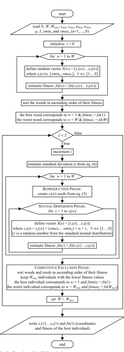
The IWO is an iterative method, completed within a predefined number I of iterations and inspired by the behavior of weeds in nature. The mathematical model of this behavior forms the IWO algorithm. According to this model, three phases are applied at every i-th (i=1,…,I) iteration: (1)
Reproduction, (2) Spatial Dispersion, and (3) Competitive Exclusion.
In the beginning of the optimization process, a population of W weeds is distributed in an N-dimensional space, where N
is the number of optimization variables xn. Therefore, the
position of each w-th weed is defined by the vector
1
2
N
X w x w x w x w . Also, in the beginning, the values of xn(w) (n=1,…,N, w=1,…,W) are
produced by a uniform random number generator inside the interval [xminn, xmaxn], where xminn (n=1,…,N) and xmaxn
(n=1,…,N) are user-defined parameters. The interval [xminn,
xmaxn] is actually the search space of variable xn. Besides,
every weed is assigned a fitness value, which depends on the weed position as given below:
1
, 2 ,..., N
fit w fit x w x w x w (4)
In the reproduction phase, every weed produces a number of seeds si(w), which is a linear function of the weed fitness as
given below:
int
max min
min ,1,..., & 1,..., i i i
i i
fitmax fit w
s w s s s
fitmax fitmin i I w W
where fitmini and fitmaxi are the extreme fitness values at the
i-th iteration, while smin and smax are user-defined parameters
that represent the extreme values of si. It seems that weeds
with low fitness values (good weeds) produce more seeds than weeds with high fitness values (bad weeds). Therefore, a good weed is more capable of finding better positions inside the search space than a bad one.
The spatial dispersion is the 2nd phase, where the seeds produced by a weed in the previous phase are dispersed around this weed according to a normal distribution with standard deviation given by the following expression:
max min
min , 1,...,1
i
I i
i I I
(6)
where σmin and σmax are the extreme values of σi, while μ
determines the decreasing rate of σi and is called non-linear
modulation index. It is obvious that σi is the same for all the
population at a given iteration. However, σi refers to seed
dispersion in a unitary search space (i.e., the search space where xmaxn–xminn=1). If an optimization variable xn
corresponds to a non-unitary search space, then the actual standard deviation for this variable is set equal to
xmaxnxminn
i.In the competitive exclusion phase, all the members of the colony (weeds and seeds) are sorted according to their fitness values, and only the best Wmax ones (i.e., the Wmax members with the lower fitness values) survive, while the rest ones are terminated. In this way, only the good weeds are able to keep searching for better positions in the next iterations.
In total, the user-defined parameters required by the IWO algorithm are: xminn (n=1,…,N), xmaxn (n=1,…,N), I, W,
Wmax, smin, smax, σmin, σmax and µ. The above optimization procedure of the IWO method is graphically given in Fig. 3.
V.FITNESS FUNCTION DESCRIPTION
[image:4.595.306.542.66.736.2]It is obvious that the optimization problem is inherently multi-objective since several requirements must be satisfied at the same time. On the other hand, the IWO, like every other evolutionary optimization method, aims at minimizing a single mathematical function, which is the fitness function mentioned above. In order to simultaneously satisfy multiple requirements by applying such a method, the fitness function must be described as a linear combination of terms, where each term is an expression of a respective requirement. When the fitness function finds the global minimum point, all the terms have achieved their respective minimum values, which means that all the requirements have been satisfied. According to the requirements described in Section II, the fitness function is defined as follows:
Fig. 3. Flow chart of the IWO method. end
write x1(1)…xN(1) and fit(1) (coordinates and fitness of the best individual)
set W = Wmax COMPETITIVE EXCLUSION PHASE: sort weeds and seeds in ascending order of their fitness
keep Wmax individuals with the lower fitness values the best individual corresponds to w = 1 and fitmini = fit(1) the worst individual corresponds to w = Wmax and fitmaxi = fit(Wmax)
for w = 1 to W
REPRODUCTION PHASE: create si(w) seeds from eq. (5)
SPATIAL DISPERSION PHASE: for s = 1 to si(w)
define vector X(s) = [x1(s)…xN(s)]
where xn(s) = xn(w) + (xmaxn – xminn) × σi × r, n[1…N] (r is a random number from the standard normal distribution)
estimate fitness fit(s) = fit(x1(s)…xN(s)) false
the best weed corresponds to w = 1 & fitmini = fit(1) the worst weed corresponds to w = W & fitmaxi = fit(W)
i < I
increment i true
estimate standard deviation σi from eq. (6) start
read N, W, Wmax, smin, smax, σmin, σmax,
µ, I, xminn and xmaxn (n=1,…,N)
initialize i = 0
sort the weeds in ascending order of their fitness for w = 1 to W
define random vector X(w) = [x1(w)…xN(w)] where xn(w)[xminn, xmaxn], n[1…N]
1 min 2
3 max
4 max
max , 2 2
max , 20 20
max , 1.8 1.8
fit k FG k GF k SLL
k SWR
(7)
where, FGmin, GF, SLLmax and SWRmax are respectively the minimum forward gain (in dBi), the gain flatness (in dB), the maximum SLL (in dB) and the maximum SWR, found over the entire operating bandwidth, which, in our case, is 800-3300 MHz. To estimate the above four values, the values of FG,
SLL and SWR are calculated over the range 800-3300 MHz at steps of 10MHz by employing the NEC software. Finally, k1,
k2, k3 and k4 are user-defined positive coefficients, which aim to balance the minimization of the four terms shown in (7) or reinforce the minimization of any of these terms in cases when this term is not minimized as the rest ones.
As the value of FGmin increases, the 1st term of (7) decreases. Thus, this term aims at maximizing FG over the entire bandwidth. The next three terms are formed so that values of GF less than 2dB, values of SLLmax less than –20dB and values of SWRmax less than 1.8 do not cause further minimization of the fitness function, since the desired values of FG, SLL and SWR have already been achieved. Finally, it has to be noted that the 3rd term of (7) aims at satisfying not only the SLL requirement but also the requirement for the desired value of FBR (FBR≥20dB).
VI.OPTIMIZATION RESULTS
The IWO method is used here to design an optimal 12-element LPDA (M=12) for operation in the frequency range 800-3300 MHz under the requirements given in Section II. As mentioned in the last paragraph of Section IV, some parameters need to be defined in order to execute the IWO algorithm. Therefore, the initial and the maximum weed population are both considered to be composed of 20 weeds (W=Wmax=20). The number of seeds produced by a weed ranges from smin=0 (for the worst weed) to smax=5 (for the best weed) and is calculated from (5) according to the weed fitness value. The boundary values for the standard deviation of the seed dispersion are σmin=0 and σmax=0.15, while the non-linear modulation index μ is set equal to 2.5. The optimization procedure is completed within 2000 iterations (I=2000).
The optimization variables are Lm (m=1,...,12), rm
(m=1,...,12), Sm (m=1,...,12) and Z0, i.e., 37 variables in total (3M+1=37), as explained in Section II. Therefore, the weed position is defined by the vector
1 2 37
1 2 12 1 2 12 1 2 12 0
X x x x L L L r rr S S S Z (8) which means that the variables xn (n=1,...,12) are the dipole
lengths Lm, the variables xn (n=13,...,24) are the radii rm, the
variables xn (n=25,...,36) are the distances Sm, and finally x37 is
equal to Z0. The radius limits are rmin=0.001m and
rmax=0.005m. In order to avoid elements touching each other, the lower limit of the distances between adjacent elements is
considered to be Smin=2rmax+0.002=0.012m. The upper limit of the distances is considered to be Smax=λmax/4=0.094m, where
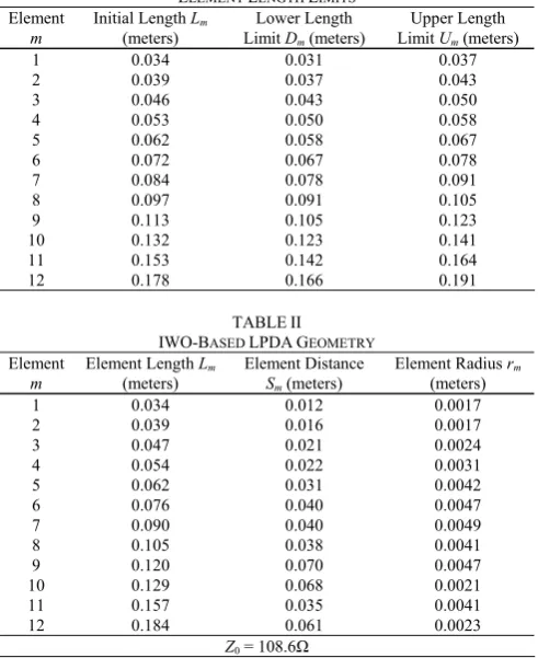
λmax is the wavelength at 800MHz, considering that the maximum variation of voltage, current or impedance is obtained along a quarter of the maximum wavelength (i.e., at 800MHz). The values of Z0 range from 50 Ohm to 200 Ohm. Finally, the limits of the element lengths are derived separately for each element and are based on length values derived from Carrel’s method. In particular, from the corrected Carrel’s graph, [46], and by considering antenna directivity equal to 7.5dBi, it results τ=0.86 and σ=0.16 (optimum σ value). The length L12 of the largest element is set equal to half-wavelength at the lower operating frequency (i.e., at 800MHz) and is then reduced approximately by 5% due to the element thickness. The rest of the lengths (L1,…,L11) are calculated from (1). These initial values are shown in the 2nd column of Table I. The average length value
LmLm1
2 of two adjacent elements is considered to be the upper limit Um for Lm and the lower limit Dm+1 for Lm+1. In this way, all the length limits are estimated except for D1 andU12. These can be considered to be at the same distance from the respective lengths as the opposite limits (U1 and D12) from the same lengths, i.e., U1L1L1D1 and
12 12 12 12
U L L D . All the length limits are given in columns 3 and 4 of Table I. The idea for different length limits restricts the search space of the element lengths and helps in this way the optimization procedure to reach faster the optimum result.
The geometry of the optimized LPDA extracted from the IWO algorithm is given in Table II. The total LPDA length is calculated from the expression
11
1
T m
m
S S (9)
and is found equal to 0.393m. In order to examine the performance of the proposed method, a new LPDA is designed by applying Carrel’s method and is compared to the IWO-based LPDA. To have a fair comparison between the two LPDAs, the new LPDA is composed of the same number of elements (i.e., 12 elements), has the same length (0.393m), operates in the same frequency range (800-3300 MHz) and uses a short-circuited stub of proper length as does the IWO-based LPDA. As mentioned in Section II, the short-circuited stub helps the large LPDA elements to reduce the current that may arise due to high-order resonances induced on these elements. The geometry of this LPDA is given in Table III. From both the LPDA geometries given in Tables II and III, the values of SWR, FG and SLL versus frequency are extracted by applying the NEC software and are displayed respectively in the comparative graphs of Figs. 4, 5 and 6. These graphs are used to find the minimum, the maximum and the mean value as well as the standard deviation of SWR, FG
range. These values are given in Table IV.
From Fig. 4, it is easy to realize that the LPDA derived from Carrel’s method has better behavior in terms of SWR
within the entire bandwidth. Nevertheless, the IWO-based LPDA produces SWR values less than 2, which means that it satisfies the impedance-matching condition over the entire bandwidth according to the literature.
In addition, as shown in Fig. 5, the values of FG produced by the Carrel-based LPDA have rapid variations with significant drops, which cause an increase in the value of GF. It seems that this behavior is due to high-order resonances induced on large LPDA elements despite the use of the stub. On the contrary, the IWO-based LPDA exhibits a smoother variation of FG and a value of GF less than the required value of 2dB (also see Table IV).
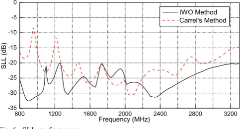
Finally, the SLL values produced by the IWO-based LPDA are kept below the desired value of –20dB inside the whole operating bandwidth, as shown in Fig. 6. On the other hand, Fig. 6 confirms the inability of Carrel’s method to perform
SLL control. It seems that the IWO method has the ability to suppress high-order resonances, while Carrel’s method does not, even with the use of a short-circuited stub of proper length.
TABLEI
INITIAL ELEMENT LENGTH VALUES DERIVED FROM CARREL’S METHOD AND
ELEMENT LENGTH LIMITS
Element
m Initial Length (meters) Lm Limit Lower Length Dm (meters) Limit Upper Length Um (meters)
1 0.034 0.031 0.037
2 0.039 0.037 0.043
3 0.046 0.043 0.050
4 0.053 0.050 0.058
5 0.062 0.058 0.067
6 0.072 0.067 0.078
7 0.084 0.078 0.091
8 0.097 0.091 0.105
9 0.113 0.105 0.123
10 0.132 0.123 0.141
11 0.153 0.142 0.164
12 0.178 0.166 0.191
TABLEII IWO-BASED LPDAGEOMETRY
Element
m Element Length (meters) Lm Element Distance Sm (meters) Element Radius (meters) rm
1 0.034 0.012 0.0017
2 0.039 0.016 0.0017
3 0.047 0.021 0.0024
4 0.054 0.022 0.0031
5 0.062 0.031 0.0042
6 0.076 0.040 0.0047
7 0.090 0.040 0.0049
8 0.105 0.038 0.0041
9 0.120 0.070 0.0047
10 0.129 0.068 0.0021
11 0.157 0.035 0.0041
12 0.184 0.061 0.0023
Z0 = 108.6Ω
In overall, the IWO-based LPDA geometry satisfies all the design requirements and has better behavior in terms of GF
and SLL than the Carrel-based geometry. In other words, the IWO-based LPDA has all the desired radiation characteristics
that make it suitable for efficient multimedia content reception. Also, the IWO method seems to be a very useful design tool for future mobile computing systems.
TABLEIII CARREL’S LPDAGEOMETRY
Element m
Element Length Lm (meters)
Element Distance Sm (meters)
Element Radius rm (meters)
1 0.034 0.015 0.0010
2 0.039 0.018 0.0011
3 0.046 0.020 0.0013
4 0.053 0.024 0.0015
5 0.062 0.028 0.0017
6 0.072 0.032 0.0020
7 0.084 0.037 0.0024
8 0.097 0.043 0.0027
9 0.113 0.050 0.0032
10 0.132 0.058 0.0037
11 0.153 0.068 0.0043
12 0.178 0.087 0.0050
Z0 = 80Ω
TABLEIV
LPDAPERFORMANCE PARAMETERS
Performance
Parameter IWO Method Carrel’s Method
SWRmin 1.21 1.17
SWRmax 1.99 1.66
SWRmean 1.77 1.44
SWRstd 0.21 0.12
FGmin (dBi) 7.56 7.45
FGmax (dBi) 9.41 9.64
FGmean (dBi) 8.30 8.68
FGstd (dBi) 0.52 0.55
GF (dB) 1.85 2.19
SLLmin (dB) –32.60 –30.72
SLLmax (dB) –20.00 –8.39
SLLmean (dB) –25.71 –21.50
SLLstd (dB) 3.56 4.32
Fig. 4. SWR vs. frequency.
[image:6.595.46.292.394.695.2]Fig. 6. SLL vs. frequency.
VII.CONCLUSION
The IWO method has been applied in combination with the NEC software to design an optimal 12-element LPDA for operation in the frequency range 800-3300 MHz. The optimization has been performed under multiple requirements concerning the desired values of FG, GF, SLL, FBR and SWR. The optimized LPDA geometry has better radiation characteristics inside the entire operating bandwidth compared to a respective LPDA with the same length produced by Carrel’s method, which is the basic technique for LPDA design. This work is the first effort recorded in the literature to optimize simultaneously the values of FG, GF, SLL, FBR and
SWR over a wide frequency range. The LPDA derived from the optimization procedure is suitable for efficient multimedia content reception. Due to its effectiveness, the IWO method can be a very useful design tool for emerging mobile computing systems.
REFERENCES
[1] C. X. Mavromoustakis, E. Pallis, and G. Mastorakis, Eds., Resource Management in Mobile Computing Environments (Modeling and Optimization in Science and Technologies Vol. 3). Springer, 2014. [2] C. X. Mavromoustakis, A. Bourdena, G. Mastorakis, E. Pallis, and G.
Kormentzas, “An energy-aware scheme for efficient spectrum utilization in a 5G mobile cognitive radio network architecture,” Telecommun. Syst., Nov. 2014.
[3] K. Papanikolaou, C. X. Mavromoustakis, G. Mastorakis, A. Bourdena, and C. Dobre, “Energy consumption optimization using social interaction in the mobile cloud,” in Proc. 6th Int. Conf. Mobile Networks and Management (MONAMI 2014), 22-24 September 2014.
[4] S. Jia, C. Xu, J. Guan, H. Zhang, and G.-M. Muntean, “A novel cooperative content fetching-based strategy to increase the quality of video delivery to mobile users in wireless networks,” IEEE Trans. Broadcast., vol. 60, no. 2, pp. 370-384, June 2014.
[5] C. X. Mavromoustakis, P. Mousicou, K. Papanikolaou, G. Mastorakis, A. Bourdena, and E. Pallis, “Dynamic cloud resource migration for efficient 3D video processing in mobile computing environments,” in Novel 3D Media Technologies, M. K. Khan, Ed., New York: Springer, 2015, pp. 119-134.
[6] A. Hornbostel, A. Konovaltsev, H. Denks, and F. Antreich, “Simulation of multi-element antenna systems for navigation applications,” IEEE Syst. J., vol. 2, no. 1, pp. 7-19, Mar. 2008.
[7] E. Chiu and V. K. N. Lau, “Precoding design for multi-antenna multicast broadcast services with limited feedback,” IEEE Syst. J., vol. 4, no. 4, pp. 550-560, Dec. 2010.
[8] A.-H. Tsai, L.-C. Wang, J.-H. Huang, and R.-B. Hwang, “High-capacity OFDMA femtocells by directional antennas and location awareness,” IEEE Syst. J., vol. 6, no. 2, pp. 329-340, June 2012.
[9] T. Ali, A. Z. Sadeque, M. Saquib, and M. Ali, “MIMO radar for target detection and localization in sensor networks,” IEEE Syst. J., vol. 8, no. 1, pp. 75-82, Mar. 2014.
[10] H. Xu, H. Aliakbarian, E. Van der Westhuizen, R. Wolhuter, and G. A. E. Vandenbosch, “An architectural scheme for real-time multiple users beam tracking systems,” IEEE Syst. J., to be published.
[11] C. A. Balanis, Antenna Theory, Analysis and Design, 3rd ed., New Jersey: John Wiley & Sons, 2005, pp. 611-652.
[12] R. L. Carrel, “Analysis and design of the log-periodic dipole antenna,” Ph.D. dissertation, Dept. Elect. Eng., University of Illinois, University Microfilms, Inc., Ann Arbor, MI, 1961.
[13] P. C. Butson and G. T. Thompson, “A note on the calculation of the gain of log-periodic dipole antennas,” IEEE Trans. Antennas Propagat., vol. AP-24, no. 1, pp. 105-106, Jan. 1976.
[14] A. R. Mehrabian and C. Lucas, “A novel numerical optimization algorithm inspired from weed colonization,” Ecol. Inform., vol. 1, no. 4, pp. 355-366, Dec. 2006.
[15] Z. D. Zaharis, C. Skeberis, and T. D. Xenos, “Improved antenna array adaptive beamforming with low side lobe level using a novel adaptive invasive weed optimization method,” Prog. Electromagn. Res., vol. 124, pp. 137-150, 2012.
[16] Z. D. Zaharis, C. Skeberis, T. D. Xenos, P. I. Lazaridis, and J. Cosmas, “Design of a novel antenna array beamformer using neural networks trained by modified adaptive dispersion invasive weed optimization based data,” IEEE Trans. Broadcast., vol. 59, no. 3, pp. 455-460, Sep. 2013.
[17] Z. D. Zaharis, P. I. Lazaridis, J. Cosmas, C. Skeberis, and T. D. Xenos, “Synthesis of a near-optimal high-gain antenna array with main lobe tilting and null filling using Taguchi initialized invasive weed optimization,” IEEE Trans. Broadcast., vol. 60, no. 1, pp. 120-127, Mar. 2014.
[18] G. J. Burke and A. J. Poggio, “Numerical Electromagnetics Code (NEC) - Method of Moments,” Naval Ocean Systems Center, San Diego, CA, Tech. Doc. 116, Jan. 1981.
[19] R. C. Hansen, Moment Methods in Antennas and Scattering. Norwood, MA: Artech House, 1990.
[20] Y. C. Chung and R. Haupt, “Log-periodic dipole array optimization,” J. Electromagn. Waves Appl., vol. 15, no. 9, pp. 1269-1280, 2001. [21] M. A. Mangoud, M. A. Aboul-Dahab, A. I. Zaki, and S. E. El-Khamy,
“Genetic algorithm design of compressed log periodic dipole array,” in Proc. 2003 IEEE 46th Midwest Symp. Circuits and Systems, 27-30 December 2003, vol. 3, pp. 1194-1197.
[22] S. E. El-Khamy, M. A. Mangoud, M. A. Aboul-Dahab, and A. I. Zaki, “Fractal multiband antennas using GA/MOM optimized log periodic dipole arrays,” in Proc. 2004 IEEE Antennas Propagat. Society Int. Symp., 20-25 June 2004, vol. 4, pp. 3433-3436.
[23] T. L. Pitzer, A. James, G. B. Lamont, and A. J. Terzuoli, “Linear ensemble antennas resulting from the optimization of log periodic dipole arrays using genetic algorithms,” in Proc. 2006 IEEE Congress on Evolutionary Computation, 16-21 July 2006, pp. 3189-3196.
[24] M. Fernandez Pantoja, A. R. Bretones, F. Garcia Ruiz, S. G. Garcia, and R. G. Martin, “Particle-Swarm optimization in antenna design: Optimization of log-periodic dipole arrays,” IEEE Antennas Propagat. Mag., vol. 49, no. 4, pp. 34-47, Aug. 2007.
[25] Xiao-Lin Zhang and Huo-Tao Gao, “An optimum design of miniaturized high frequency inverted-V log-periodic dipole antenna,” in Proc. 2011 IEEE CIE Int. Conf. on Radar, 24-27 October 2011, vol. 2, pp. 1185-1188.
[26] S. M. Hashemi, V. Nayyeri, M. Soleimani, and A.-R. Mallahzadeh, “Designing a compact-optimized planar dipole array antenna,” IEEE Antennas Wirel. Propagat. Lett., vol. 10, pp. 243-246, 2011.
[27] M. Aziz-ul-Haq, M. Tausif Afzal, Umair Rafique, Qamar-ud-Din, M. Arif Khan, and M. Mansoor Ahmed, “Log periodic dipole antenna design using particle swarm optimization,” Int. J. Electromagnetics and Applications, vol. 2, no. 4, pp. 65-68, 2012.
[28] M. Touseef, Qamar-ud-Din, M. Aziz-ul-Haq, Umair Rafique, M. Arif Khan, and M. Mansoor Ahmed, “Genetic algorithm optimization of log-periodic dipole array,” Int. J. Electromagnetics and Applications, vol. 2, no. 6, pp. 169-173, 2012.
TV spectrum,” Int. J. RF Microw. Comput-Aid. Eng., vol. 23, no. 2, pp. 157-171, Mar. 2013.
[30] D. Kampitaki, A. Hatzigaidas, A. Papastergiou, P. Lazaridis, and Z. Zaharis, “Dual-frequency splitter synthesis suitable for practical RF applications,” WSEAS Trans. Commun., vol. 5, no. 10, pp. 1885–1891, Oct. 2006.
[31] D. G. Kampitaki, A. T. Hatzigaidas, A. I. Papastergiou, and Z. D. Zaharis, “On the design of a dual-band unequal power divider useful for mobile communications,” Electr. Eng., vol. 89, no. 6, pp. 443–450, June 2007.
[32] Z. D. Zaharis, D. G. Kampitaki, P. I. Lazaridis, A. I. Papastergiou, A. T. Hatzigaidas, and P. B. Gallion, “Improving the radiation characteristics of a base station antenna array using a particle swarm optimizer,” Microw. Opt. Technol. Lett., vol. 49, no. 7, pp. 1690–1698, July 2007. [33] Z. D. Zaharis, D. G. Kampitaki, P. I. Lazaridis, A. I. Papastergiou, and P.
B. Gallion, “On the design of multifrequency dividers suitable for GSM/DCS/PCS/UMTS applications by using a particle swarm optimization-based technique,” Microw. Opt. Technol. Lett., vol. 49, no. 9, pp. 2138–2144, Sep. 2007.
[34] J. C. Chen, M. H. Chiu, Y. S. Yang, and C. P. Li, “A suboptimal tone reservation algorithm based on cross-entropy method for PAPR reduction in OFDM systems,” IEEE Trans. Broadcast., vol. 57, no. 3, pp. 752–756, Sep. 2011.
[35] S. Chen, “An efficient predistorter design for compensating nonlinear memory high power amplifiers,” IEEE Trans. Broadcast., vol. 57, no. 4, pp. 856–865, Dec. 2011.
[36] Y. Wang, W. Chen, and C. Tellambura, “Genetic algorithm based nearly optimal peak reduction tone set selection for adaptive amplitude clipping PAPR reduction,” IEEE Trans. Broadcast., vol. 58, no. 3, pp. 462–471, Sep. 2012.
[37] A. H. Abdelhafiz, O. Hammi, A. Zerguine, A. T. Al-Awami, and F. M. Ghannouchi, “A PSO based memory polynomial predistorter with embedded dimension estimation,” IEEE Trans. Broadcast., vol. 59, no. 4, pp. 665–673, Dec. 2013.
[38] T. Niknam and F. Golestaneh, “Enhanced bee swarm optimization algorithm for dynamic economic dispatch,” IEEE Syst. J., vol. 7, no. 4, pp. 754-762, Dec. 2013.
[39] H. M. Hasanien, “Design optimization of PID controller in automatic voltage regulator system using Taguchi combined genetic algorithm method,” IEEE Syst. J., vol. 7, no. 4, pp. 825-831, Dec. 2013.
[40] S. Saha, “GARO framework: A genetic algorithm based resource optimization for organizational efficiency,” IEEE Syst. J., vol. 7, no. 4, pp. 889-895, Dec. 2013.
[41] A. K. Jain, S. C. Srivastava, S. N. Singh, and L. Srivastava, “Bacteria foraging optimization based bidding strategy under transmission congestion,” IEEE Syst. J., to be published.
[42] M. Naeem, A. S. Khwaja, A. Anpalagan, and M. Jaseemuddin, “Green cooperative cognitive radio: A multiobjective optimization paradigm,” IEEE Syst. J., to be published.
[43] M. de Paula Marques, F. R. Durand, and T. Abrao, “WDM/OCDM energy-efficient networks based on heuristic ant colony optimization,” IEEE Syst. J., to be published.
[44] S. Jia, C. Xu, A. V. Vasilakos, J. Guan, H. Zhang, and G.-M. Muntean, “Reliability-oriented ant colony optimization-based mobile peer-to-peer VoD solution in MANETs,” Wirel. Netw., vol. 20, no. 5, pp. 1185-1202, July 2014.
[45] C. Xu, S. Jia, L. Zhong, H. Zhang, and G.-M. Muntean, “Ant-inspired mini-community-based solution for video-on-demand services in wireless mobile networks,” IEEE Trans. Broadcast., vol. 60, no. 2, pp. 322-335, June 2014.
[46] R. Cox. (2013, May). The WB0DGF Antenna Site. LPCAD software. [Online]. Available: http://wb0dgf.com/LPCAD.htm
Zaharias D. Zaharis received the B.Sc. degree in
Physics in 1987, the M.Sc. degree in Electronics in 1994 and the Ph.D. degree in 2000 from the Aristotle University of Thessaloniki. Also, in 2011 he obtained the Diploma degree in Electrical and Computer Engineering from the same university. From 2002 to 2013, he has been working in the administration of the telecommunications network at the Aristotle University of Thessaloniki. Since 2013, he is with the Department of Electrical and Computer Engineering, Aristotle University of Thessaloniki.
His research interests include design and optimization of antennas and microwave circuits, mobile communications, RF measurements, radiowave propagation and electromagnetic scattering.
Dr. Zaharis is a member of the Greek Physics Society, the Technical Chamber of Greece and IEEE.
Christos Skeberis received the Engineering
Diploma Degree in Electrical and Computer Engineering in 2010 from Aristotle University of Thessaloniki and is currently a Ph.D. candidate in the same university.
His research interests include design and optimization of antennas, mobile communications systems, neural networks, machine learning, radiowave propagation and ionospheric phenomena.
Mr. Skeberis is a member of the Technical Chamber of Greece.
Pavlos I. Lazaridis was born in Larissa, Greece. He
received the Electrical Engineering degree from Aristotle University of Thessaloniki, Greece, in 1990, the M.Sc. in Electronics from Université Pierre & Marie Curie, Paris, France, in 1992, and the Ph.D. degree in Electronics and Telecommunications from Ecole Nationale Supérieure des Télécommunications (ENST), Paris, in 1996.
From 1991 to 1996, he was involved with research on semiconductor lasers, wave propagation, and nonlinear phenomena in optical fibers for the Centre National d’Etudes des Télécommunications (CNET) and teaching at the ENST. In 1997, he became Head of the Antennas and Propagation Laboratory, TDF- C2R Metz (Télédiffusion de France/France Télécom research center), where he was involved with research on antennas and radio coverage prediction algorithms for cellular mobile systems, DAB, and DVB-T broadcasting. From 1998 to 2002 he was with European Patent Office (EPO) Rijswijk, The Netherlands, as a senior examiner in the field of Electronics-Telecommunications. From 2002 to 2014 he was involved with teaching and research at the Alexander Technological Educational Institute of Thessaloniki, Greece, and Brunel University West London. He is currently a Reader in Electronic and Electrical Engineering at the University of Huddersfield, United Kingdom.
Thomas D. Xenos was born in Thessaloniki, Greece,
in 1955. He received the Diploma in Electrical Engineering from the University of Patras, Patras, Greece, in 1978, and the Ph.D. degree in Wireless Communications from the Aristotle University of Thessaloniki, Thessaloniki, Greece, in 1991.