2017 2nd International Conference on Computational Modeling, Simulation and Applied Mathematics (CMSAM 2017) ISBN: 978-1-60595-499-8
Research on Simulation System of Missile and Arrows Based on Unity3D
Qi WANG
*and Liang-ming WANG
College of Energy and Power Engineering, Nanjing University of Science and Technology, Nanjing Jiangsu 210094, China
*Corresponding author
Keywords: Google Earth, Visual simulation, Outer trajectory simulation platform.
Abstract. Aiming at the demand of visualization system development in flight simulation, a projectile missile flight simulation system is designed and developed. Using Unity3D to build the 3D model of the simulation object and reproduce the real environment design semi physical simulation system. By interfacing with Google Earth API platform and calling function, the 3D terrain modeling is realized by 3D Terrain Modeling Technology. And the database-based outer trajectory simulation platform simulation program data link, receive the simulation data of the ballistic simulation program, the whole process of the real-time three-dimensional animation reproduction of the reaction trajectory simulation, and add the bomb selection, playback settings, perspective tracking, explosion effects and other functions. The actual engineering shows that the system can be realistic to reflect the process of flying ammunition and has good stability and versatility.
Introduction
The research on the visual simulation of ballistic missile in China is relatively late, and the analysis and simulation system for missile combat training is in the initial stage. The only flight simulation calculation to get the relevant data and 2D curve, not a visual display of projectile flight attitude and trajectory real-time process, and affected by many factors, the actual number of tests is limited. Therefore, the visualization simulation has emerged as the times require, the purpose of this paper is to simulate the digital information into a visual, animation and image combination of the way, dynamic presentation in front of the researchers. So that researchers can observe the real-time flight trajectory, trajectory parameters and trajectory of the missile at any time.
At present, the domestic research in this area is generally a visual simulation of a ballistic missile or gun in specific terrain model, system simulation and real data driven global real terrain is rare. For example, National University of Defense Technology Professor Tang development of a certain type of air to surface missile flight visual simulation system, and several key technologies of visual simulation in preliminary research; Chongqing University associate professor Guo Maoyun using object-oriented technology, developed the rocket flight simulation system in the field of aerospace measurement and control platform of the first bid kylin. It has been widely used in urban planning, military training, weapon system development and verification, which provides an effective way for the development of weapons and equipment, tactical training and training.
Simulation Platform
Combined with practical engineering experience and the trajectory equation of projectile correction coefficient calculation in each time the whole flight process air ballistic elements, according to the calculated data files corresponding to different play types and different initial conditions, different weather conditions, so as to build the exterior ballistic simulation platform based on the database, so as to provide effective data support to drive Unity3D in the model. There are many mathematical models for calculating the trajectory. The model is modified by the following six degree of freedom rigid body trajectory model.
The establishment of specific model reference rocket exterior ballistics. The system development platform for the Unity3D simulation platform, which is a cross platform development and virtual reality engine, which is simple and intuitive workflow, a powerful set of tools, can be imported through the 3D model, image, sound and other relevant resources, with the help of Unity scene construction module, easy to create a complex virtual world. In order to obtain the desired topography, we must first obtain an authorized development key for Bing Maps. Then get the keys to Unity3D and World Composer to obtain Google Earth docking terrain image required, then using the Terrain Composer 3D terrain image into the desired position, finally loaded into the scene to Unity3D.
Model Building
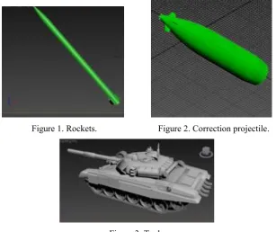
There are a large number of different types of data in the external ballistic simulation platform. This paper takes only two models as examples. It is very difficult to construct complex model directly in Unity3D, but it can be used to create the model by the professional 3D drawing software, and then the .FBX format file is generated to be imported into Unity3D. This article uses 3DMax to make the model, as shown in the figure:
[image:2.595.145.453.424.682.2]
Figure 1. Rockets. Figure 2. Correction projectile.
Figure 3. Tank.
3D Terrain Modeling and Implementation
In the Unity3D can make their own terrain, in general, can be imported through the creation of the environment resources to create Terrain resources and then get the appropriate editing. But for the flight process, usually large regional span, so according to the traditional way of operation a lot of work, and we hope to do the best to simulate flight on real terrain in flight process. Therefore, in this paper, we use World Composer to get the required terrain image from Google Earth, and then transform it into the 3D real terrain in the Unity3D scene. Satellite images can be derived from the highest zoom level 19, that is, each pixel resolution of 0.3 meters, the height of the zoom data level of 14, each pixel resolution of 10 m image. But considering the actual hardware and the overall optimization problem, this paper adopts the method of multi-level image, which is in the selected area, the area near the emplacement of the high resolution selection of one to two square kilometers area, and then create a larger area of new low resolution and superposition in the periphery, generally three to four this paper selects the class to a Washington area terrain as an example. In addition to altitude and satellite image processing, combined with Terrain Composer plus cloud shadows, trees, grass and objects to make unlimited changes and editing. After the completion of the modification can be directly generated three-dimensional terrain of large areas, pay attention to the terrain should be set as a collision body, to prevent the body from passing through, and to trigger the projectile explosion event.
Particle Effects
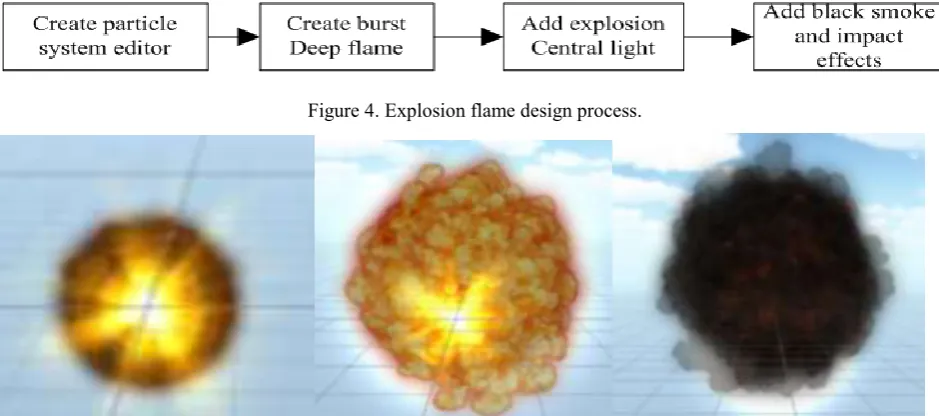
[image:3.595.60.530.465.673.2]In order to more accurately reproduce the flight process of the projectile, this paper adds the effect of the missile to the ground, and the effect of adding the tail flame to the rocket. The explosive effect is constructed by the particle system, which is composed of a large number of particles with a certain shape, color, position, velocity, life cycle and so on. [5]. The explosion effects of particle system is composed of a plurality of superposition, control time and life cycle in response to different particle system, with particle curve editor to create complex particle effects, synthesizing realistic dynamics, explosion effects of the production process is as follows:
Figure 4. Explosion flame design process.
Figure 5. Effect of explosion.
Game Interface Design
GUI.Label (newRect (20,60, Screen.width, 20), t_str, lableStyle); label information setting. If (New Rect (60, 10, 60, 30), "replay", buttonStyle); control button settings (GUI.Button).
The main way to realize the visual angle switching function is to adjust the relative position of the camera and the bullet in the program code by clicking the button to create the control of the third person lens. Then set the camera position angle and other information to achieve the appropriate results, the initial definition of the code as follows:
[AddComponentMenu("CameraControl/Follow")] public Camera mainCamera;
public Transform camera;
camera.position =new Vector3(15000, 4000, -15000); camera.rotation=Quaternion.Euler(0, 0, 0);
Draw the flight trajectory using LineRenderer line renderer in panoramic flight, pay attention to the use of the world coordinate system to set the color, width, the projectile through the point of a connecting flight trajectory finally formed.
Data Access and Platform Docking
Unity3D script editor MonoDevelop script editor, support for Java, C# and Boo three languages, taking into account and external ballistic table platform data communication, the code in the VS2010 using C#. Simulation system flow:
1)First, the initial projectile firing table platform to select the desired angle, weather conditions and other related parameters in the trajectory, call the corresponding DLL program to calculate the flight process of the ballistic data, choose one path of the output TXT file.
2)The core of the simulation is the real data driven, and in turn the table is generated by the call to generate the suffix.Unity3d file format. Unity3D animation process is a frame of the enabled MonoBehaviour, the Update is called in every frame, Update is related to the current platform frame, and FixedUpdate is the real time, so when dealing with the physical logic to put the code in the FixedUpdate instead of Update. The essence of the missile model is to read a set of continuous one-dimensional data frame and reproduce it, so we need to call the I/O data stream. In the Unity3D real data are stored in the Web Stream data, can not be used directly to read the FileStream class, or after the final release of data will be released, the table can not be driven on the table. So you need to use the WWW class to read the data and create a web page HTML file to the WebPlayer platform to publish, generate .Html and .Unity3d format two files: .unity3d file which is loaded by the Unity Web plugin, the HTML code of the page through the UnityObject2 remote C#Script file interaction. Main data read the following code:
using System.IO; public WWW www;
IEnumerator loadtxt(){string Filepath = "file://" + "C:/FSA"+ "/output.txt" WWW www = new WWW(Filepath);
yield return www; _txt= www.text;}
To read the data stored in _txt, and the data into a two-dimensional dynamic array, one-dimensional representation, the other represents a column of ballistic elements, each frame of a row of data loading operation run sequentially, using Time.timeScale control the refresh speed.
the relative position of the side and rear, to achieve panoramic effect. Finally select the Web Settings in Build Player and check the Offline Deployment check box release. Select the code as follows:
panduan=float.Parse(_txt.Substring(0,2)); if(panduan==1){
huojiandan.SetActive (true); huopao.SetActive (false);}
4) at the end of the table table call.Unity3d file can see the visual simulation process, the main code is as follows:
public void animation()
PgeAnimation.Controls.Clear();
var unity = new AxUnityWebPlayerAXLib.AxUnityWebPlayer(); ((System.ComponentModel.ISupportInitialize)(unity)).BeginInit(); this.Controls.Add(unity);
((System.ComponentModel.ISupportInitialize)(unity)).EndInit(); unity.src = Application.StartupPath + "\\105火炮.unity3d"; AxHost.State state = unity.OcxState;
unity.Dispose();
Visual Simulation Results Analysis
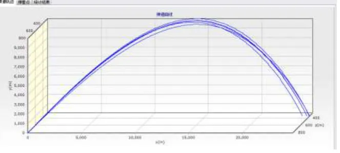
[image:5.595.135.467.382.531.2]In the shooting table platform in the conventional flight simulation, using the TChart control can be drawn as shown below:
Figure 6. Trajectory.
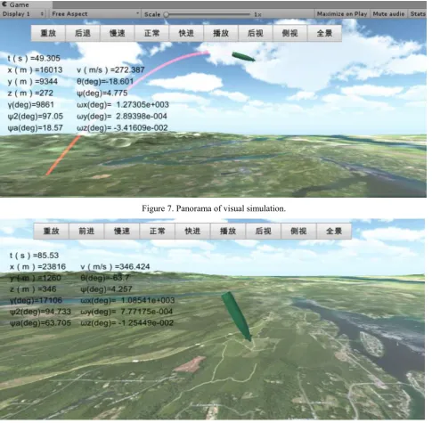
Figure 7. Panorama of visual simulation.
Figure 8. Side view of visual simulation.
The 3D animation can be seen in every moment of body posture, and can be observed through the details of the control operation, observe the flight process of projectile at different angles by changing relative motion and camera modeling, field scene make flying more realistic. It is also easier to see if the program has a problem with the data, and it is easier for non-professionals to understand.
Conclusion
true representation of the simulation process of the whole project, after the actual test, based on the database of the Unity3D guided missile visual simulation real time, and realistic, basically achieve the desired effect, suitable for distributed interactive 3D visual simulation platform.
References
[1] Zi-peng Han. Rocket exterior ballistics [M]. Beijing Institute of Technology press, 2008.
[2] Hai-shan Zhang. Research and implementation of 3D visual simulation system for conventional ballistic missile [D]. National University of Defense Technology, 2008.
[3] Ji-an Cui. Research and implementation of a three dimensional real time simulation system for rocket flight based on winning Kirin [D]. Chongqing University, 2014.
[4] Jian-wen Shu, Ming Wu. Simulation study of shadow elimination in Virtual Aviation scene [J]. Computer Simulation, 2013, 30 (8).
[5] Rong-kai Zhan. Simulation of flame and explosion in virtual scene using particle system theory [J]. Computer Simulation, 2004, 26 (2).
[6] Li-li Zhang. Unity3D and database communication method [J]. Computer Technology and Development, 2014, 24 (3).
[7] Heng Zhang, Mao-Jun Zhang. Study on the generation and management of 3D terrain model [J]. Journal of System Simulation, 2007, 17 (2).
[8] Xia Wei. Development and application of military scene simulation system [D]. Beijing Institute of Technology, 2012.
[9] Cong Cuo, Shou-Zun Wang. Design of flight visual simulation system based on [J]. Unity3D Electronic Design Engineering, 2016,23 (5).
[10] Yu-hang Zheng, Hai Yu, Ya-Xiu Yu. Application of visual simulation technology in military field [J]. National Defense Technology Foundation, 2003,4 (12).