2017 2nd International Conference on Computer Engineering, Information Science and Internet Technology (CII 2017) ISBN: 978-1-60595-504-9
Simulation Analysis and Comparison of Self
Regulating Synchronous Valve and Fixed
Synchronous Valve Based on AMESim
PEIYI ZHANG, WEIHUI WANG and ZEQI CHEN
ABSTRACT
As an important component of hydraulic synchronous control technology, synchronous valve has been widely popularized in engineering applications. At present, the domestic production of most of the synchronous valve is fixed synchronous valve, when fixed synchronous valve is in variable flow condition, its synchronization accuracy will be reduced. In this paper, ZSTF2-B2-10H type reversing piston synchronous valve is taken as the object of study, the main task is to study the analysis of the original type step valve dynamic performance in the condition of the shunt, on the basis of this research, self-regulating synchronous valve is introduced, under the condition that the parameters of the synchronous valve remain the same, comparative analysis of dynamic characteristics of partial load and variable flow conditions, thus establishing the superiority of self-regulating synchronous valve.
INTRODUCTION
Open loop control system is widely used because of its convenient manufacturing, simple structure and low cost compared with the former. Open loop synchronous control system often uses synchronous valve hydraulic components for synchronous control. It has the advantages of convenient maintenance, simple structure, and reliable accuracy and so on. At present, most of the fixed synchronous valve used on it, the flow is relatively high, in order to overcome this drawback, Yang Shixiang Professor developed a self-adjustable synchronous valve, greatly enhance the performance of the synchronous valve.
In this paper, AMESim software is used to simulate the two synchronous valves of fixed type and self-regulating type, and the main performance indexes of two kinds of synchronous valves are compared and analyzed.
THE BASIC PRINCIPLE AND MODELING OF FIXED SYNCHRONOUS VALVE
Working Principle
Synchronous valve is a synchronous devices commonly used in the loop synchronization system, it can automatically allocate the oil flow into two or more hydraulic actuators, to keep their position synchronous or in accordance with a certain proportion of sports. It is known that a double cylinder hydraulic circuit adopts a fixed _________________________________________
type synchronous valve, the model is ZSTF2-B2-10H, and the technical parameters are shown in table 1. Let's give a brief introduction of the shunting operation as an example.
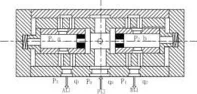
When the synchronous valve is in the shunt condition, as shown in Figure 1, the A and B ports are for exit. The cavity oil chamber and the b cavity oil chamber are respectively communicated with the left end and the right end spring cavity. In the spring to ensure that the valve in the middle position, the pressure oil from the P port through the fixed orifice inflow, respectively to a and b cavity oil chamber, when A is equal to B, at both ends of the pressure valve in the middle position, when the external load is not the same, if the A pressure increases, the spool does not act, the two branch of total liquid resistance is equal to △Pa, resulting in Q1 decrease, q1<q2 due to p1<p2, the spool moves to the left, so that the left variable orifice opening becomes large, liquid resistance is reduced, at the same time, the variable orifice opening is reduced, liquid resistance increased, and Q1 increased, Q2 decreased, until q1=q2, p1=p2, at this time, the spool to achieve new balance two the velocity of actuators to achieve synchronization. Among them, the function of the fixed orifice is to change the flow signal into the pressure signal and feed back to the left and right spring cavities. The function of the variable flow orifice is to compensate the pressure, and the over-current area is controlled by the feedback of p1 and p2. The flow collecting condition is similar to the shunt operation principle, and the entrance is opposite to the outlet [2].
Synchronous Valve Modeling
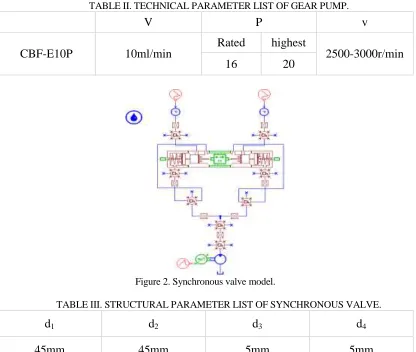
[image:2.612.203.400.474.568.2]Since the shunting condition and the flow collecting condition are only opposite to the input and output directions, here we introduce the model establishment of the shunting operation separately. The model of synchronous valve is ZSTF2-B2-10H, and the specific parameters are shown in table 1. Gear pump model is CBF-E10P, specific parameters are shown in table two. Next, we use AMESim's HCD (hydraulic component design) module to model the synchronous valve, as shown in figure 2.
Figure 1. Shunt working principle diagram.
TABLE I. TECHNICAL PARAMETER LIST OF SYNCHRONOUS VALVE.
D P △P △ V Vm
TABLE II. TECHNICAL PARAMETER LIST OF GEAR PUMP.
V P v
CBF-E10P 10ml/min
Rated highest
[image:3.612.92.508.54.406.2]2500-3000r/min 16 20
Figure 2. Synchronous valve model.
TABLE III. STRUCTURAL PARAMETER LIST OF SYNCHRONOUS VALVE.
d1 d2 d3 d4
45mm 45mm 5mm 5mm
da db K
43mm 43mm 1.4N/mm
Table 3: d1 and d2 are the equivalent diameters of the left and right sides of the
spool; d3 and d4 are the left and right orifice diameters; da and db are the left and right
spring seat diameters; and the K is the spring stiffness coefficient.
Simulation Analysis
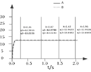
Figure 3. Flow curve.
As shown in Figure 3, the flow curve at both ends of the synchronizing valve under the action of 4 differential pressures. As can be seen from the diagram, according to the coordinate value, when the pressure difference between the two ends is 0, there is still a slight error in the traffic at both ends. With the increase of complex pressure difference, the flow difference at both ends increases gradually.
The error is the main performance indexes of shunt epsilon synchronous valve, namely the work branch A and B flow rate of the difference of Q two times for the inflow of the synchronous valve flow ratio of Q:
=2 q Q/ (1)
When the maximum load deviation is obtained, the epsilon is 0.875% < 3% is obtained. Thus, the model of the synchronous valve is established correctly and the parameters are set properly.
RESEARCH AND ANALYSIS OF SELF REGULATING SYNCHRONOUS VALVE
The flow rates of A and B branches are:
2g p
2g p
A A
B B
q CA
q CA
In the formula, C is the discharge coefficient; A is the primary orifice area; g is the acceleration of gravity; is oil gravity density; pA is the left side throttle pressure
drop; pB is the right side throttle pressure drop;
(2)
FB( p A p )B (4)
B is the cross-sectional area of the spool.
F=F / 2Bp (5)
In the formula, p is half of the total flow, flow through one side of the orifice, the
pressure drop; F is the spool movement resistance, that is, the aforementioned fluid power, spring force and the sum of friction; F is shunt error coefficient for hydraulic
power.
As can be seen from the above, to ensure the accuracy of the synchronization valve, it is necessary to ensure that once the throttle orifice area and a throttle orifice pressure drop, that is, to maintain the basic flow of the total unchanged. If the flow is reduced by half, the fixed pressure synchronous valve for the fixed throttling orifice will be reduced to 1/4 of the original, and the synchronization accuracy will be greatly reduced [4].
In order to effectively overcome the impact of fluid power and flow changes on the synchronous valve, we introduce a self-regulating synchronous valve, the working principle shown in figure 4.
Working Principle
The orifice of the valve sleeve and the edge of the sleeve valve form a throttling orifice. Split flow conditions, into the synchronization valve of the oil flow through the bottom of the sleeve valve, through the throttle orifice, throttle after the oil into the spool at both ends, while the left side of the oil is led to the upper side of the spool. Thus, the pressure drop is controlled by a spring and remains constant. In the flow collecting condition, the oil on the right throttling orifice is introduced into the lower side of the sleeve valve, and the sleeve valve and the lower piston move upwards together. It seems that, regardless of the shunt condition or the flow collection condition, and the flow rate, the orifice pressure drop is always constant, thus ensuring the synchronization accuracy under the condition of flow change.
Formula deduction
By the principle of its operation, we can know:
P A1 1k x1 P A2 2
(6)
In the formula, P1 and A1 are the upper pressure and the force area of the sleeve
spool, P1 can also be expressed as A cavity pressure; P2 and A2 are the lower pressure
and force area of the sleeve spool, P2 can also be expressed as inlet pressure; K1 is the
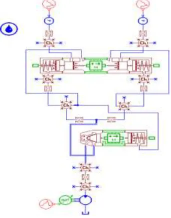
Figure 4. Principle diagram of self-regulating shunt valve.
Figure 5. Self-regulating shunt valve model.
Figure 6. The displacement spool curves of two kinds of synchronous valves at different flow rates.
Simulation Analysis
The diagram shows the displacement spool curve of the fixed synchronous valve, and the displacement spool curve of the self-regulating synchronous valve is shown below. The comparison shows that when the flow changes, self-regulating synchronous valve spool displacement changes than the fixed type synchronous valve is smaller, and the dynamic response time variation in variable flow conditions, synchronization accuracy and higher self-adjustable synchronous valve. At the same time, from the fixed synchronous valve displacement, spool curve changes can be seen, the flow of its impact is much greater than the former. Therefore, the self-regulating synchronous valve is more suitable for the system with larger flow rate or larger flow range.
CONCLUSION
The basic work principle based on the in-depth understanding of the synchronous valve on the application of AMESim for modeling, simulation and analysis are carried out, focusing on the synchronization accuracy and dynamic characteristics are studied, and the introduction of self-adjustable synchronous valve, compared with fixed type synchronous valve, to determine the superiority of self-regulating synchronous valve.
ACKNOWLEDGMENTS
Under the guidance of my tutor, I successfully completed this thesis. In the thesis writing, the teacher gave me a lot of help, especially in the field of simulation modeling. On the occasion of the completion of this thesis, I would like to extend my high respect and heartfelt thanks to my mentor, Professor Wang Weihui!
REFERENCES
1. Zhang Jun, Paul Curtis. Research and Simulation of synchronization system, hydraulic rope adjusting device based on AMESim mining machinery, 2013 (6).
2. Lv Qihui, .Improved design of hydraulic synchronous valve structure, mechanical design and manufacture, 2007 (6): 8-10.
3. Zou Xuexin, Liao Jinjun, Li Xin. Simulation study of hydraulic fluid pressure complementary synchronous loop. Hydraulic, pneumatic and sealing, 2013.
4. Xu Li, Pang da. Simulation and analysis of hydraulic synchronous valve flow collection based on AMESim [J]. Mechanical science and technology, 2012 (9): 1535-1538.