Top-Down Virtual Environment Construction for Manufacturing Simulations
Zhijie Xu and Dave Taylor
School of Engineering University of Huddersfield Queensgate Gate, Huddersfield HD1 3DH, United Kingdom
Abstract: Virtual environments (VEs) are becoming important tools for simulating manufacturing systems. Various virtual environment constructing techniques and toolkits have been devised in recent years. This paper provides an “inside” view of those methods. Based on the insight, a futuristic VE construction approach that aims to integrate manufacturing application knowledge with environment data is proposed and its implementation discussed.
Keywords:virtual reality, virtual environment, manufacturing simulation
1 Introduction:
Simulation has been widely considered one of the most useful tools for analysing and designing complex manufacturing systems [1]. However, the conventional simulation modellers have two fundamental problems. Firstly, simulation modellers often encounter difficulties in transforming the real world multi-dimensional, visual and dynamic characteristics into the one-dimensional, textual and static representation required by traditional simulation languages [2]. The result of such presentation produced from the conventional simulation process is often hard to understand, manipulate and utilize. The second problem is due to the difficulties on integrating design and manufacturing information [3].
Virtual Reality (VR) and Virtual Environment (VE) techniques have provided a new dimension in solving those problems by integrating more human senses into a computer-generated real-time 3-D interactive environment. Hence, the VR application users will have better insight of the simulated system and its potential problems. One challenge for achieving those purposes is to find a format that supports the representation of VE-based manufacturing knowledge and, paradoxically, the simplification of the environment construction and application data management processes.
Despite system functions claimed by various vendors, the current utilities for constructing VR environments are still left for users because commercial VR systems need to remain as general as possible to accommodate different users. The construction of VR environments is still application specific and consequently involves time consuming processes often led to poor system usability.
2 Literature Review
Current virtual environment construction toolkits can be classified as geometric library-based programming functions, interpreted environment modelling scripts, and, the most popular, commercial VE authorisers.
2.1 API based approach
Application program interface (API) methods rely on stand-alone or built-in 3D programming libraries or interface functions that enable advanced users to write system code using, say, C/C++ and Java languages. The code developed by the users is normally built into an executable program or a series of interpretable "class" files that generates a dedicated virtual environment.
WorldToolkit (WTK) from Sense8 Co.Ltd is a library of over 1000 functions written in C that enable user to develop new virtual reality applications [4]. WTK functions are organized into over 20 classes. These classes include the Universe (which manages the simulation and contains all other objects), Geometries, Nodes, Viewpoints, Windows, Lights, Sensors, Paths, Motion Links, and others. Functions are included for things such as device instancing, display setup, collision detection, loading geometry from a file, dynamic geometry creation, specifying object behaviour, manipulating textures, and controlling rendering. The architecture of the WTK incorporates the power of scene hierarchies which is a tree-like structure that manages all the contents and contexts in a virtual environment. By calling different functions, user can build a simulation by assembling “nodes” into a hierarchical scene graph, which dictates how the simulation is rendered and allows all of the efficiencies of a state-preserving, stack-oriented rendering architecture. Each “node” of the scene graph (or scene graphs) represents part of the simulation.
Except those commercial programming libraries mentioned above, researchers in various universities and institutes have developed a series of customised APIs. For example, researchers in the University of Maryland [6] have developed VE construction software – Metis, a toolkit for building immersive virtual environment with environment-independent application computing components. The Metis toolkit defines an application-programming interface (API) on the simulator side, which communicates via a network with a standalone viewer program that handles all immersive display and interactivity.
Researchers at Advanced Interface Group (AIG) in the University of Manchester have developed a system that tackles problems on constructing large-scale applications. This system aimed to deliver the performance and flexibility required by the large-scale complex application environments, which addresses the graphics, interaction, distribution and systems architecture problems [7]. Similar to the Metis system described above, this proposed system also separates the simulation task and environment rendering process into two core components, Maverik and Deva: Maverik manages the world as a participant perceives it, and Deva manages the "reality" behind this perception. The Maverik has functions for optimized display management including culling, spatial management, interaction and navigation, and control of VR input and output devices. It allows data exchange between its core functions and external application data so that optimal representation and algorithms can be employed. Deva extends Maverik to support the distributed applications and controls the environment simulation.
Other developments have been reported in the literature review including VEDAM system developed by Angster [8] in Washington State University and Interactive Virtual manufacturing Environment developed by the University of Bath [9]. All the API based methods introduced above provide flexibility for environment developers to create a large and complex virtual environment. However, they demand high-level programming skills, for example, MFC and ActiveX, and the generated environments provide no flexibility for users to change and reconfigure, when different applications requirements are involved.
2.2 Virtual reality modelling language
The Virtual Reality Modelling Language (VRML) is a script language to describe VEs and an ISO standard (International Standard ISO/IEC 14772) for specifying 3D virtual worlds networked via the Internet. The VRML environment on the World Wide Web (WWW) can link to or be linked from other sources on the Internet, but the use of VRML for constructing virtual environments is very much similar to the API method. VRML files describe 3D objects and worlds using the hierarchical scene graph. The scene graph contains nodes which describe objects and their properties. It contains
hierarchically grouped geometry to provide an audio-visual representation of objects, as well as nodes that participate in the event generation and routing mechanism. Entities in the scene graph are called nodes. VRML 2.0 defines 54 different node types, including geometry primitives, appearance properties, sound and sound properties, and various types of grouping nodes.
2.3 Graphical VE authorisers
Currently, the most common way to build a virtual environment is using an environment authoriser, which is a graphical user interface that works in a drag-and-drop manner similar to an ordinary CAD system. For example, the SuperscapeVRT is an integrated visual-based virtual environment developing tool set. It consists of two browser platforms (one for desktop application and one for Internet usage) and a suite of seven editors. Virtual all the development work involved in the process of constructing an virtual environment can be completed in the VRT, from creating 3D objects to organising their spatial positions, from editing sound clips to painting background images.
Similar to the VRT, Sense8 World Up is also an Integrated Development Environment (IDE) from which you create objects and properties, and design simulations. WorldUp supports the import of 3D models from industry standard modellers. To add behaviours to objects, developers can author customer behaviours or change a property of an existing behaviour by writing scripts using the BasicScript language, or use property change events to trigger behaviours.
2.4 Contextualizing the VE construction
approaches
Virtual environment construction approaches can be simplified as Bottom-up generative Approach, Event-driven Building-block Approach, and Variant Construction Approach. The first approach focused on environment geometric modelling and detailed object grouping and layout. The second approach required system developer's skills in implementing application knowledge in sequencing environment activities. The third approach noticed the importance of application environment data integration and management. All three approaches are able to constructing “exhibition-style” environments, i.e., 3D models for display and manipulation. To the knowledge of authors, there are limited methods available for constructing virtual environments, and, at the mean time, being able to support application knowledge acquisition and environment data management. The difficulties of achieving this can be summarized as follows:
3D polygon rendering geometry, animation elements and other virtual environment sensory factors. Such abstracted low-level VR elements must have real world semantic meanings so that a virtual application environment could be constructed not only to have a visual resemblance but also to functionally perform like its physical counterpart. Abstraction of physical (geometrical and functional) reality into a VR model is not a generic problem due to the diversity of application requirements. So far little research toward this problem has been reported in the literature.
(2) Practical virtual environment applications require large-scale and complex VR models. However, currently available construction methods to create even a reasonably small-scale VR model, for example, a human head, are a tedious and time-consuming and expensive process.
(3) A unique difficulty exists when application environments need to be modelled in a higher degree of accuracy than that of, say, virtual environments for entertainment. The precision of VR modelling is mainly driven by the internal application data rather than by the VR rendering result or graphical visualization effect.
(4) A large proportion of application data and information required in a VR model is empirical and non-generic. Although one of the strengths of a VR model is that it can deal with such knowledge without a knowledge base, the data needs to be strictly monitored and managed within the model. Incorporating a graphically correct (or even crude) VR models with a complex, diverse application database is a challenging problem.
(5) Application reconfigurability is essential for most multi-user and multi-purpose virtual environments. At present, VR models are mostly created by VR specialists or programmers. The hidden model structure and non-transparent modelling data leaves users little flexibility to make changes especially when an application requirement has been changed.
To overcome those problems, works need to be done on (i) establishing effective methods for rapid creation of large and complex virtual environments that can be reconfigured, and (ii) providing techniques for acquiring application knowledge and managing environment data within a application environment that is accessible for the third party analysis tools.
3 Domain-Analysis Top-Down Approach
A domain analysis-based top-down approach is proposed in this research that can satisfy three needs: (i) to provide a user-friendly and rapid method for the construction of virtual manufacturing environments, (ii) to provide a reusable and re-configurable mechanism of virtual environments for different manufacturing applications and (iii) to allow the capture and presentation of manufacturing knowledge and manage manufacturing
data. The proposed approach was implemented with the aid of two concepts: application domain analysis and top-down VE construction.
3.1 Application domain analysis
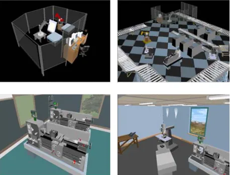
Application domain-analysis attempts to understand, classify and abstract the real world knowledge into a virtual environment and provides realistic guidance for the constructing of the applied environment. For example, a virtual lathe would carry the knowledge of its spindle speeds and the chunk would carry the knowledge of the diameter range it could hold. The approach negates the need to encapsulate all the knowledge in to a single environment.
[image:3.595.306.535.407.582.2]Consider an environment designed for a process planner, the knowledge needed on a machine tool would relate to spindle power available, job-type and machine capacity. On the other hand, a plant layout designer will merely require data concerning the machine footprint, and possibly, some safety factors. In this way the application domain-analysis actually performs the task of identifying which part of manufacturing knowledge is going to be applied in a specific environment.
Figure 1 Template Manufacturing Environments
3.2 Top-down VE construction
A computing system named Knowledge Acquisition and Management using Virtual Reality (KAMVR) has been
developed with an environment knowledge database at its core. All constitutional virtual objects from the aforementioned template environments and their rendering information are managed and stored by it. Also stored is the manufacturing knowledge data, such as machine specifications. At system run-time, the object graphical representation data are bound with corresponding manufacturing knowledge data in a dynamic-link mode to enable environment simulation and control.
4 KAMVR System
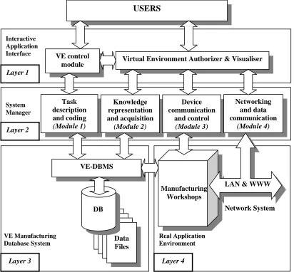
The KAMVR system has four layers. Each layer has its related functional modules, see Figure 2.
4.1 The system structure
Layer 1 is an interactive virtual environment interface used to create, visualize and interact with the virtual
environments. It also deals with the adoption of virtual reality peripheral devices.
USERS
Interactive Application Interface
Layer 2 - the 'System Manager' - is the main knowledge handling and data management layer with four constituent modules. The task description and coding module (Module 1) is a programming utility for application domain-analysis and task coding based on the template environments and manufacturing information stored in the VE database. The knowledge representation and acquisition module (Module 2) supports the real-time data exchange between virtual environments and the database for environment retrieval, modification, and configuration. The device communication and control module (Module 3) is a program for processing signals received from real world manufacturing equipment. In the prototype system, an Audit lathe, a Bridgeport milling machine, a PUMA 560 robot and a Lansing PWIOII robot were connected. The networking and data communication module (Module 4) is used for manufacturing cell communication and Internet connection for VE-based on-line training. The KAMVR System Manager forms the heart of the system structure and is pivotal for connecting virtual environment application interface with the VE control
module Virtual Environment Authorizer & Visualiser
Task description and coding
(Module 1)
Knowledge representation and acquisition
(Module 2)
Device communication
and control
(Module 3)
Networking and data communication
(Module 4)
VE-DBMS
System Manager Layer 1
Layer 2
LAN & WWW Manufacturing
Workshops
Network System DB
VE Manufacturing Database System
Real Application Environment
Data Files
[image:4.595.85.497.112.494.2]Layer 3 Layer 4
database system and the protocols of real manufacturing equipment.
Layer 3 is a dedicated VE-manufacturing database, which includes a database management system (DBMS) and a database with domain-specific data files. It manages the template virtual manufacturing environments and related manufacturing tasks.
Layer 4 contains the real manufacturing environment for virtual manufacturing based process planning and workshop control.
4.2 Data administration
In the KAMVR system, there are two classes of data being stored - template environment data and manufacturing data.
[image:5.595.78.513.236.453.2](1) Template environment data. This is arranged in six data files in a relational database, including Environment, Object, Shape, Standard, Static, and Dynamic files. The Environment data file contains template environment general information such as name and type. Each of the environments has a distinctive environment code (Envcode) as the index key to start the environment at system run-time. The Object file stores a unique object ID number, its relative type and numbers. It has a many-to-one relationship with the Environment table through the key field - environment ID. The remaining data files deal with virtual object property data (i.e., object sizes and positions are saved in the Standard Information Table, while the object rotational data would be saved in the Dynamic Table) and has a one-to-one relationship with the Object Table. For example, a query to locate an object’s rotational speed along the X-axis will require the object and the environment number to retrieve the record. Instead of manually keying in all the template environment data, scanner utility has been incorporated to
automatically save all the data from an environment into the database. This utility relies on the VE graphical structure – an upside-down tree-like hierarchy. Every object in the hierarchy has parent, child and sibling relationships with other objects. The structure allows an exhaustive search of all the objects in an environment and access to their property data structure to store in the database until it reaches the “Root Object”, which is a common virtual universe that holds all the objects created in it.
(2) Manufacturing information. For implementing manufacturing knowledge into virtual environment
applications, the database is used as a bridge. The manufacturing knowledge considered here can be considered as, static facility information and dynamic machining data.
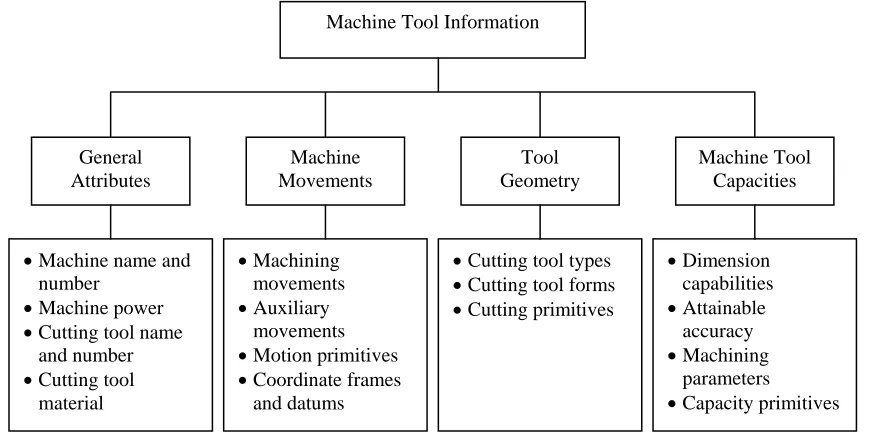
Machine Tool Information
General Attributes
Machine Movements
Tool Geometry
Machine Tool Capacities
• Machine name and
number
• Machine power
• Cutting tool name and number • Cutting tool
material
• Machining movements • Auxiliary
movements • Motion primitives • Coordinate frames
and datums
• Cutting tool types • Cutting tool forms • Cutting primitives
• Dimension capabilities • Attainable
accuracy • Machining
parameters • Capacity primitives
Figure 3. Static facilities information
Static facilities mainly include machines and cutting tools as shown in Figure 3, which consist of physical and functional facts that play an important role in determining machining conditions, optimising processes and selecting machines and cutting tools.
processes and geometrical forms to be represented and provide a basis for conjugating environment and manufacturing information.
Figure 5 KAMVR System Interface
4.3 System implementation
The KAMVR system has an integrated platform developed using Microsoft Visual C++ and Superscape 3D Control, where virtual environments, database, and application programs are all embedded objects. The platform acts as a comprehensive controller for user-environment interaction, enabling user-environment-database interaction, monitoring environment simulation and facilitating virtual and real environment communication, see Figure 5. At simulation run-time, the system starts from coding manufacturing task for environment retrieval. Then, the retrieved template environment is automatically loaded in the embedded visualiser. Application users can modify the environment according to their specific requirements. Finally, the modified is initialised and the simulation started.
5 Conclusions
The research presented in this paper has provided an easy-to-use method for users to construct rapidly large and complex virtual manufacturing environments. Further research is required to establish such real-time control with different manufacturing systems. Research work is also needed to explore the potential for developing an integrated VR based manufacturing knowledge base for data acquisition and process knowledge management of different manufacturing systems.
References
[1] Ozdemirel, N. E., Mackulak, G. T., and Cochran, J. K., 1993, A group technology classification and coding scheme for discrete manufacturing simulation models. International Journal of Computer Integrated Manufacturing, 31(3), 579-601.
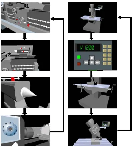
Figure 4 KAMVR Machine Operations
[2] Ülgen, O. M., and Thomasma, T., 1990, SmartSim: An Object Oriented simulation program generator for manufacturing systems. International Journal of Computer Integrated Manufacturing, 28(9), 1713-1730.
[3] Bullinger, H. and Roessler, A., 1998, Using Virtual Reality to Enhance Productivity. The Proceedings of the VEs’98 Conference (Eurographics Workshop in Stuttgart, Germany), ISBN 3-211-83233-5.
[3] Dam, A., 2000, Scientific Visualisation: A Progress Report. The Proceedings of IEEE Virtual Reality 2000 Conference, ISBN 0-7695-0478-7.
[4] WorlToolKit Reference Manual, 1999. Engineering Animation, Inc. Sese8 Product Line.
[5] The Java 3D API Specification, 1998. Corporate & Professional Publishing Group, Addision Wesley Longman, Inc. ISBN 0-201-32576-4.
[6] Turner, R., Li, S., and Gobbetti, E., 1999. Metis – an Object-Oriented Toolkit for Constructing Virtual Reality Applications. Computer Graphics Forum, Vol.18, No.2, pp122-130.
[7] Cook, J., Hubbold, R., Keates, M. Virtual Reality for Large-Scale Industrial Applications, Future Generation Computing Systems, Vol. 14, No. 3/4, pp.157-166, ISSN 0167-739X.
[8] Angster, S. R., 1996, VEDAM: Virtual Environments for Design and Manufacturing. Ph.D. Dissertation, Washington State University.
[image:6.595.55.280.129.377.2]