Systems
GC27 -6999-0
File No. 8360/$370-09
Introduction to
Programming
th~
First Edition (February 1973)
Changes made to this first edition will be reported in subsequent revisions or technical newsletters.
Before using this publication in connection with the operation of IBM systems, refer to the latest IBM System/360 or System/370 SRL Newsletter, Order NO. GN20-0360 for editions that are applicable and current.
Copies of this and other IBM publications can be obtained through your IBM branch office.
BEFORE YOU USE THIS BOOK
Who This Book Is For
This book
is
for programmers and other people who need to knowwhat's involved in programming the IBM 3270 Information Display System.
For those programmers who plan and code the messages seen on 3270 displays, this book may be the only book required.
For those programmers who also write the access method macro
instructions or other I/O instructions, this book
is
to be usedin conjunction with the appropriate access method or IBM Program Product publications.
How This Book Is Organized
This book
is
divided into these sections:1: SCREEN DESIGN
Introduces important 3270 concepts. Shows an example of
what a 3270 display message might look like, what coding elements are required to write this message in your program, and how terminal operator input might be handled.
2: SCREEN MANAGEMENT
Suggests macro definitions and programming routines that might be written to encode and decode messages to and from the display.
3 : DEVICE MANAGEMENT
Suggests including I/O operations (reading, writing, error
recovery)
in
a module separate from message formatting.Contains flowcharts to aid in writing error recovery rou-tines for use with BTAM.
Other Books You May Need
As a general introduction to the 3270:
An Introduction to the IBM 3270 Information Display System, GA27-2739
To understand how the terminal operator will see the 3270:
Operator's Guide for IBM 3270 Information Display System, GA27-2742
IBM 3270 Information Display System Problem Determination Guide, GA27-2750
As a reference on how the 3270 works:
IBM 3270 Information Display System Component Description, GA27-2749
Suggested programming tools:
A green booklet: IBM 3270 Information Display System
Ref-erence Summary, GX20-l878
Panel layout sheets: IBM 3270 Information Display System
Layout Sheet, GX27-2951
If you are using BTAM:
IBM 2260 BTAM and 2260 GAM to IBM 3270 BTAM Conversion Guide,
GC27-6975
IBM System/360 Disk Operating System Basic Telecommunications
Access Method, GC30-500l
DOS Pro rammin Su
lement for the 3270 Information Dis la
System, GC27-6977
{appl~cabe to DOS Re ease 26 only
DOS
Version4 BTAM, GC27-6978
IBM System/360 Operating System Basic Telecommunications
Access Method, GC30-2004
OS/VS BTAM, GC27-6980
If you are using TCAM:
Planning f'or TCAM with the IBM 3270 Information Display
Sys-tem, GC30-202l
OS TeAM Programmer's Guide and Reference Manual, GC30-2024
OS TCAM User's Guide, GC30-2025
SECTION 1: SCREEN DESIGN
Fi eld Concept • • • • • . •
How Fields are Defined
What Attributes May be Assigned to a Field
Example of Field Definition •
Panel Design
. • • . • . • • •
• • • •
This is a Panel:
• • • • •
• • • • •
An Example of a Sequence of 3270 Panels
Planning a Sequence of Panels • • • •
Defining the Purpose of Each Panel
• • • •
Using the Panel Layout Sheet
• • • •
An Example of Laying Out a Panel
Data Stream Coding and Decoding •
Elements of a Data Stream • • • '.
Orders
• • • • • • • • • • • • •
Adding Orders to the panel Layout Sheet
Coding the Panel
Write Control Character (WCC)
Repeat to Address Order • •
Analyzing Input Data
The Operator's Response
Attention Identifier (AID)
Input Data
• • • • • •
SBA Codes • • • • • • • • •
Program Attention Keys
Program Access (PA) Keys
Program Function (PF) Keys
Selector Pen Input and Output •
Selector Pen Field Format •
Designator Characters • • •
. • • •
The Relationship of one Data Stream to Another
Modifying Existing Panels •
.1 • • •Write Control Character (WCC)
Erase Unprotected to Address
Erase all Unprotected Command • •
Repetitive Output • • • • •
Program Tab . • • • •
SECTION 2: SCREEN
MANAGE~£NT• • • •
Decoding and Generating Data Streams
Decoding Read Modified Input Data Stream
Nonselector Pen Data Streams
• • • • •
Immediate Selector Pen Data Stream
Mixed READ Modified Input Data Streams
Building Output Data Streams
Static Data Streams • • • • • • • • •
Semi-Dynamic Output Streams •
Dynamic Output Streams
Automatic Copy Function • •
SECTION 3: DEVICE MANAGEMENT
Techniques for Managing Devices • • • • •
The Advantages of a Terminal Control Program
The Advantages of a Master Terminal Program • •
Techniques for Keeping Track of Device Status •
Reliability and Error Recovery
• • • • • • • • •
Remote Leased Line Event Completion Analysis
Remote Dial Event Completion Analysis • •
Local Event Completion Analysis • •
Sense/status Analysis • • • • • • • • •
CONTENTS
· . . . 1
• . • . 1 • • • . 1 • • • • 2
4
• • • • 7 7 8
• • 12 • 12 12 · 13 • • 15 • 15
• • 16 • 16
20
• 23
25 • 26 • '26 • 26
27
28 • • 28 • • 28 29 • 29 • • • • • • • 29
• 30
32
• 32
• 34 35 • 36 39 39
• • 41 • • • • 41
• • 42
• • • • • • 43 • • • 46 • • • • 48 48
• 49
• 51 51 • • 52
• • 55
• 56 • • 56 • 56
• • 57
• 58
• 58
• 71
• 82
• • • 91
ILLUSTRATIONS
Figure 1. Example of 4 fields and attribute characters.
·
· ·
·
2Figu:r'e 2. Results of keyboard and field combinations 3
Figu:r-e 3. Example of attribute specification 4
Figure 4. An example of a panel ~ ~
..
. . . .
. . . .
.
·
·
· ·
7Figure 5. Another example of a panel
. . . . . .
· ·
·
·
7Figure 6. Panel 1 of an accounts receivable application
.
. · · · ·
8Figure 7. Panel 2, showing the results of a search on a customer
name • • • • • • • • • • • • • • • • • • • • • • • • 9
Figure 8. Panel 3, showing the customer's open invoices. • • • • • 9
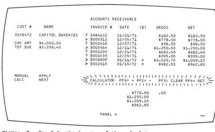
Figure 9. Panel 4, showing use of the calculator • • • • • • 10
Figure 10. PanelS, showing selection of invoices after using the
calculator • • • • • • • • • • • • • • • • • • • • 11
Figure 11. Panel 6, showing new balance after posting 11
Figure 12. Sign-on panel block diagram • • • • • • • • • • 12
Figure 13. Block diagrams • • • • • • • . • • . • • • • • 13
Figure 14. Sign-on panel as written out on layout sheet • • 13
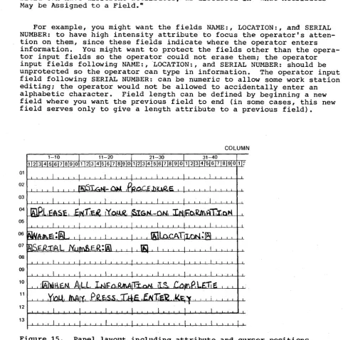
Figure 15. Panel layout including attribute and cursor positions • • 14
Figure 16. Laying out field attributes • • • • • • • • • • • 15
Figure 17. Text items on panel layout sheet • 16
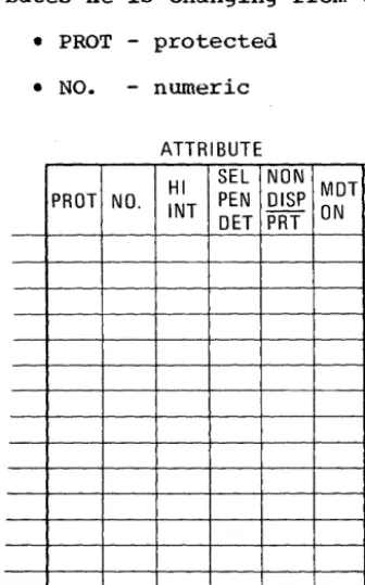
Figure 18. Field attributes • • • • • • 17
Figure 19. Attribute default values • • • • • 18
Figure 20. Completed order and attribute information. • 19
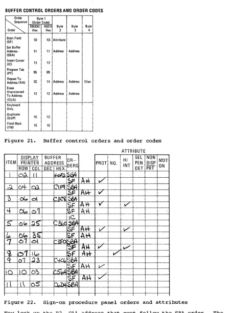
Figure 21. Buffer control orders and order codes • • • 21
Figure 22. Sign-on procedure panel orders and attributes • • 21
Figure 23. Attribute character combinations in hexadecimal • • 22
Figure 24. Assembly language statements for sign-on panel. • • • • • 23
Figure 25. WCC hexadecimal codes • • • • • • • • • 24
Figure 26. Example of RA order • • • • • • • • • • 25
Figure 27. Sign-on panel with operator's input. • 26
Figure 28. Input data sequence • • • • • • • • • 26
Figure 29. Attention identifiers (AID) in hexadecimal codes • 27
Figure 30. Definition of field for selector pen operation • • • • • 30
Figure 31. Sample panel for Selector Pen detection • • • • 31
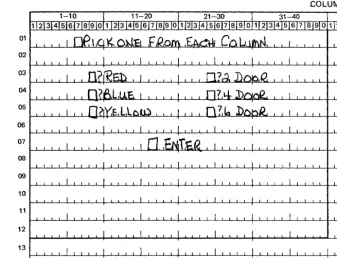
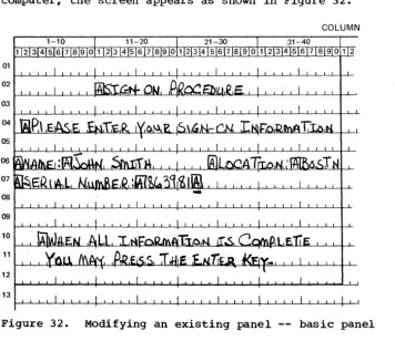
Figure 32. Modifying an existing panel -- basic panel • • • • • • • 32
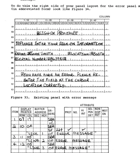
Figure 33. Existing panel with error message • • • • • • • 33
Figure 34. Panel layout changes for error message (keyed to text) • 33
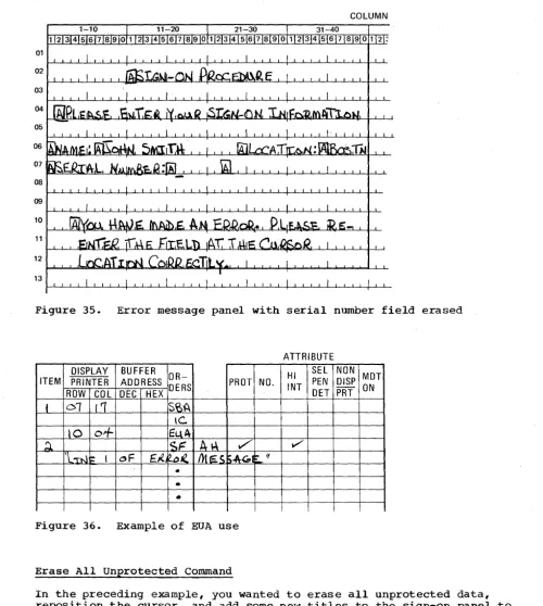
Figure 35. Error message panel with serial number field erased • • • 36
Figure 36. Example of EUA use • • • • • • • • • • • • 36
Figure 37. Sign-on panel with three erased fields • • • • • 37
Figure 38. Erasing multiple fields with EUA • 37
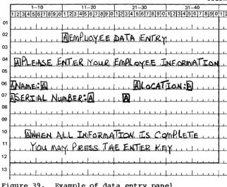
Figure 39. Example of data entry panel • • • • • • • 38
Figure 40. Data entry panel with entered data • 38
Figure 41. Employee data panel • • • • • • • • • 39
Figure 42. Panel defined with program tab • • • • • • 40
Figure 43. Relationship of screen management to device management
and application programs • • • • • • 42
Figure 44. Table of requirements • • • • • • 45
Figure 45. Example of Selector Pen panel • • • • • • • • • • • • 47
Figure 46. Sample mapping table • • • • • • • • • • • • • 48
Figure 47. Table of control unit and terminal information • • • • • 58
Figure 48. Example of a user-built DECB extension • • • • • • 59
Figure 49. DOS BTAM remote leased line READ completion analysis • • 60
Figure 50. OS BTAM remote leased line READ completion analysis • • • 61
Figure 51. DOS BTAM remote leased line WRITE completion analysis • • 67
Figure 52. OS BTAM remote leased line WRITE completion analysis • • 68
Figure 53. DOS BTAM remote Dial READ completion analysis • • • • • • 72
Figure 54. OS BTAM remote Dial READ completion analysis • • • • 73
Figure 55. DOS BTAM remote Dial WRITE completion analysis • • 77
Figure 57. Figure 58. Figure 59. Figure 60. Figure 61. Figure 62. Figure 63.
DOS BTAM local READ completion analysis • • • • • OS BTAM local READ completion analysis
DOS BTAM local WRITE completion analysis OS BTAM local WRITE completion analysis • • Sense/status conditions, keyed to Figure 62 • Sense/status byte information and its meaning Sense/status recovery actions • • • • • • • •
• 83 • • 84 • 87
• 89
• • • • 92
94
• 96
SECTION 1: SCREEN DESIGN
FIELD CONCEPT
People dealing with information see i t as a collection of individual
elements. For example, what we know about John Smith's employment may
be a collection of individual elements: his name, serial number.
loca-tion, and date of hire. The size of the element is the amount of data
required to convey useful information. You do not think of "J" and
·0"
and "R" and nNw as useful individually, but collectively, as the name
JOHN. You do not think of JOHNSMITH963981BOSTON070262 as being useful
collectively, but see the elements individually: name: JOHN SMITH,
serial number: 963981, location: BOSTON, date of hire: 07/02/62.
Each data element has its own characteristics. In this example, the
serial number is 6 numeric digits and varies from employee to employee. The word "NAME" is 4 characters, is alphabetic, is all uppercase, and
does not change. When people record these elements of data on paper
they take on such additional characteristics as position (where on the sheet of paper the item is written). color (what ink or media is used), size of the letters, and writing style.
In the past, when information was handled by a data processing device
i t was generally handled as an artificial entity called a record. The
contents and characteristics of a record were primarily determined by device requirements and little or no attention was given to the
indivi-dual information elements. Data processing users had to adjust their
thought pattern to conform to the machine requirements.
The IBM 3270 Information Display System recognizes that people deal
with individual units of information. The system has been designed to
conform to human needs and requirements and i t enables you to deal with data by individual elements or "fields," each with its own individual characteristics.
You may describe data to the 3270 on a field basis and specify the
characteristics or "attributes" of each individual field. The 3270 then
provides program and data control based on your individual field definitions.
How Fields are Defined
Each data field is established by writing a field attribute control
code, or attribute character, as the first position of the field. A
field is defined as the attribute character, plus all the data following
i t up to the next attribute character. The placement of attribute
characters defines the field lengths, and the content of the attribute
characters defines the other field characteristics. In the following
examples, the symbol [] designates an attribute character.
All the characters in a field, except the attribute character itself, assume identical characteristics based on the specifications within the
attribute character. In Figure 1 the characteristics of the field NAME:
are controlled by the attribute
GO
and the field NAME: is terminatedby the attribute ~. The placement of attributes controls the length
of the fields.
r---,
1 FIELD 1 FIELD 2 FIELD 3 FIELD 4 I
, _ _ _ _ _ ____________ ________ ________ 1
I r---, r---l r---l r---, r---, 1
I
I
1
l ___ 1 J1
NAME12
l ___ J1
JOHN B DOE l ___13
J1
SERIAL:I
l ___ 4 J1 963981
I
l ___ JI
· .
·1
I
l ______________________________________________________________________ JFigure 1. Example of 4 fields and attribute characters.
Field attributes may be modified or removed by a 3270 program.
Removal of the attribute character
[II
causes NAME: JOHN DOE tobecon-sidered by the 3270 as a single field. Changing the content of the
attribute
[l]
alters the characteristics of SERIAL even though SERIALitself has not been altered and i t still remains associated with that attribute.
What Attributes May be Assigned to a Field
Besides length, which is controlled by the position of attributes, you may specify additional characteristics with the attribute character:
Protection: A field is either protected or unprotected. When i t is
protected, i t means that the operator cannot enter or modify data in any location within that field.
In an unprotected field, the operator can enter characters or can delete or modify characters that are already there, with the keyboard. Headings, labels, titles, and formats are commonly specified as
pro-tected. Any field in which the 3270 operator should enter or modify
data must be specified as unprotected.
In Figure 1, NAME: would most likely be specified as protected.
JOHN B DOE would be specified as protected if i t was written by the
com-puter and is to remain unchanged. If JOHN B DOE is to be entered or
modified by the operator, the attribute
rn
must specify unprotected.Character content: A field is either alphameric or numeric. An
opera-tor can enter alphameric, numeric, or special characters in an alphamer-ic field.
The numeric attribute is more complex; i t depends upon whether the Numeric Lock feature is present and which keyboard is attached to the
display. Figure 2 shows what characters may be entered with various
combinations of keyboards and field types.
Visibility and netectability:A field is either displayable or
nondis-playable. When i t is displayable, and i t contains characters, those
characters are displayed. When i t is nondisplayable, any characters
within that field will not be displayed. The nondisplayable attribute
is useful for entering classified or security information at a display
unit that is in public view. Nondisplayable data is accepted by the
3270 but i t is not visible on the screen.
All characters within a displayable field can be displayed at regular brightness or at a high intenSity so that they stand out among regular
display fields. High intensity may be used to call attention to error
conditions or to highlight protected or format fields. Normal intensity
may be used for all input fields, so the terminal operator can tell at a
glance which fields require operator action. You should not specify
unprotected fields as high intenSity since such fields may become
selec-tor pen detectable (if this feature is installed) if the operator enters
r---T---T---T---T---T---,
I
I I I I I Resulting Characters II
I KeyboardI
Shift I I t---T---T---~I Keyboard INumeric IKey IField I I IDisplayedlRead Into I
I Type I Lock IPressedlType IProtectedlIn BufferlOn ScreenlStorage I
~---+---+---+---+---+---+---+---~
ITypewriterlNo INo I Alpha INo I Lowercase I Uppercase I Lowercase I
I I I lor I I I I I
I I I I Numeric I I I I I
t---+---+---t---+---t---+---t---~
I Typewriter I No IYes I Alpha INo IUppercaselUppercaselUppercasel
I
I
I lor I I I I II I I I Numeric I I I I I
t---+---+---+---+---+---+---t---~
ITypewriterlYes INo I Alpha INo I Lowercase I Uppercase I Lowercase I
~---+---+---t---t---+---t---+---~
I Typewriter I Yes IYes I Alpha INo IUppercasel Uppercasel Uppercase I
t---+---+---t---+---+---~---~---~
I Typewriter I Yes INo I Numeric I No ICan only enter 0-9, period, I
I I I
I
I land minus sign; any otherI
I I I I I Icharacters lock keyboard. I
~---+---+---t---+---t---~
I Typewriter I Yes IYes INumericlNo ICan only press dup key; any I
I I I
I
I lother action locks keyboard. I~---+---+---t---+---+---~
IData EntrYINo
1--
I Alpha INo IAlpha keys produce uppercase II I I I I lalpha characters. Numeric I
I I I I I Ishift key produces numeric I
I I I I I I characters. Alpha shift key I
I
I I I I I has no ef f ect • I~---+---+---+---t---+---~
IData EntrYINo
1--
I Numeric I No INumeric shift key has noI
I
I
I I I I effect. Alpha shift key II
I
I II
loverrides numeric specifica- II I I I I Ition and allows alpha I
I I I I I Icharacter entry. I
~---+---+---t---+---+---~
IData EntrylYes
1--
I Alpha INo IAlpha keys produce uppercaseI
I I I
I
I lalpha characters. Numeric II I I I
I
Ishift allows numeric charact-II
I II
I
ler entry. Alpha shift key II
I I II
lhas no effect.I
~---+---+---+---+---+---~
IData EntrylYes
1--
I NumericlNo ICan only enter 0-9, period, II 1 I 1 1 Idup, and minus sign. Numeric I
, I I
I
I Ishift key allows numeric I1
I
I I I Icharacter entry, alpha shift II I I I I Ikey allows alpha character I
I I I I I I entry. I
L __________ ~ ________ ~ _______ ~ _______ ~ _________ ~ _____________________________ J
Figure 2. Results of keyboard and field combinations
Fields are specified as either detectable or nondetectable. When a
field is detectable, i t can be used for selector pen operations. A
non-detectable field location can not be detected by the Selector Pen. You
are urged to designate all detectable fields as protected to prevent the the operator's changing the content of the sensitive field.
Transmission: The most corr~on operation of the 3270 (Read Modified)
sends to the computer only those fields which have been entered,
deleted, or changed by the operator. The 3270 keeps track of such
modi-fications and uses that information to select data to send to the
com-puter. If you wish to pass a field into the computer regardless of
modification, you may assign the "modified" or "modified data tag (MDT) on" attribute.
You can decide which combination of attributes you want within the
limitations specified in the IBM 3270 Component Description. Certain
attribute combinations produce additional characteristics. For example,
the numeric (limiting keyboard use) and protected (eliminating keyboard use) attributes seem contradictory but when specified together automat-ically skip the cursor past the field.
You should also be aware that the computer is not limited by
attri-butes. The computer may, for example, place alphabetic information in a
field defined as numeric, or protected, or both. The operator does not
have such liberty . .
If you do not specify any combination of attributes, a field is assumed to have the following attributes:
• alphameric
• unprotected
• displayable (at regular brightness)
• nondetectable by the Selector Pen
• not modified
You will find that these attributes are the most commonly used.
The attribute character for each field utilizes a single nondisplayed and protected character position on the screen and serves as a visual separation between successive fields.
Example of Field Definition
A typical sign-on procedure illustrates how you might define fields. Figure 3 illustrates a simple procedure in which the computer requests the operator to provide his name, location, and serial number.
FIELD 1: "SIGN-ON PROCEDURE"
This field is a heading which is a permanent part of the screen's format
and which the operator should not be able to alter. I t is unnecessary
for the words "SIGN-ON PROCEDURE" to be returned to the computer when
the ENTER key is pressed. This field should be protected, alphameric,
displayed at normal intensity, not detectable by the Selector Pen, and
not modified. All default attributes can be assumed, except that you
must specify this field as protected.
o
SIGN-ON PROCEDUREo
PLEASE ENTER YOUR SIGN-ON INFORMATION0NAME:~_
o
LOCATION: 0~ SERI AL NUMBER:
[K]
IAJ
o
WHEN ALL INFORMATION IS COMPLETE YOU MAY PRESS THE ENTER KEYFIELD 2: npLEASE ENTER ••• INFORMATION"
You should specify this field as protected. Remember that the
charac-teristics of a field are determined by the attribute character at the
beginning of the field. Field 1 and field 2 have identical attributes
and are adjacent to each other. You may choose to define them
separate-ly and use two attribute characters or you may choose to omit the
attri-bute character at the beginning of field 2. In the latter case the two
headings combine to become a single field of greater length.
FIELD 3: "NAME:"
This field should be protected, alphameric, not modified, and not
detectable by the Selector Pen. The heading could be displayed at high
intensity. Specify the protected and high intensity attributes (the two
deviations from the default attributes).
FIELD 4: the area following "NAME:"
The null area following NAME: is an input area for the operator and
must therefore be unprotected. The 3270 marks this field as modified if
anything is entered into i t , so you should not specify the modified
attribute. The default attributes (alphameric, unprotected, displayable
at normal intensity, not detectable by the Selector Pen, and not
modi-fied) apply. Use a default attribute at the beginning of this field.
The maximum number of characters the operator can enter is determined
by the length of this field. The length is equivalent to the number of
nulls, or available positions on the screen, between the attribute character for field 4 and the attribute character for field 5.
FIELD 5: n LOCATION: II
The attribute character for this field is the same as that specified for
field 3; protected and high intensity should be specified. This
attri-bute prevents the operator from keying a name longer than the maximum
length desired. If the name is shorter than the maximum field size, the
operator presses the TAB key when the name is complete. The TAB
auto-matically skips the cursor past protected fields, such as this one, and stops at the first character position in which data can be entered (the
next unprotected field). In this example, the cursor would be
posi-tioned for entry of location. If the operator attempts to key too many
characters (a name greater than 17 characters in the example) the cursor
is positioned under this attribute for the 18th character. The next
keystroke attempts to destroy this attribute but fails to do so since
attribute characters are protected. The keyboard will be inhibited, the
clicker will shut off, and the "input inhibited" indicator will turn on. The operator's attention is assured since this condition requires pres-sing the RESET key to continue.
If the attribute character for this field were omitted, the word
"LOCA-TION:" would become part of field 4 and would be normal intensity and
unprotected. This is undesirable since the operator could continue
ent-ering name information beyond the desired maximum length and could modi-fy the heading information by entering data in the screen locations occupied by "LOCATION:."
FIELD 6: the area following "LOCATION:"
This field is for operator input and theref~re must be unprotected. The
rest of the default attribute values apply and so a default attribute
may be used. You need specify only that a field is to begin following
"LOCATION:." This field ends with the attribute character at the
begin-ning of field 7, which determines the length of the field.
FIELD 7: "SERIAL NUMBER:"
This field, like "NAME:" and "LOCATION:" should be specified as
pro-tected and high intensity. This also limits the location field length
to 5 characters. Note that if field 6, the input field for location,
were defined as always a five-character code, field 7, "SERIAL NUMBER:", could be defined auto-skip to save the operator from having to press TAB after filling in the location code.
FIELD 8: the area following "SERIAL NUMBER:"
The null area following "SERIAL NUMBER:" is an input area for the
operator and must be unprotected. It should also be specified as
numer-ic so that if the operator tries to enter alphabetnumer-ic data in the field (and the keyboard has the Numeric Lock feature), the keyboard inhibits ent'ry of the incorrect character, the keyboard clicker shuts off, and the "input inhibited" indicator appears at the right of the screen to
notify the operator of the error. The improper character does not
appear on the screen and the correct digit may be entered after the operator presses the RESET key.
The serial number in the example always contains a fixed number of
digits and
is
the last field entered. The maximum length of the fieldis
determined by the location of the attribute for the next field. Butthe next field in the example is too far away ("WHEN ALL ••• KEY").
By placing an additional attribute character following input field 8,
the operator cannot enter a serial number that is too long. If the
positions allocated to the serial number are filled, the next keystroke locks the keyboard, as in the name and location fields.
This additional length check is used here because this
is
the lastfield to be entered. If you had another field to enter after SERIAL
NUMBER, i t might be more advantageous to omit this length check, as
explained in field 9.
FIELD 9: the area between the additional attribute described in Field 8
and "WHEN ALL •• • KEY"
By definition, the additional attribute character you used to delimit
the serial number field begins a new field. The protected attribute
alone is sufficient for this field and this attribute limits length for
the serial number field. Normally, however, protected (output) fields
that follow fixed-length input fields should be defined as protected and
numeric. The protected and numeric attribute defines a field as
auto-skip. Auto-skip automatically positions the cursor at the location
fol-lowing the attribute character for the next unprotected field, which is
the next place you want to key data. This technique saves keystrokes
for the operator. When the operator keys the last character of the
pre-ceding fixed-length field, the cursor normally enters the next field,
which may be protected. But since the next field is auto-skip, the
cur-sor skips this intervening protected field, and automatically positions itself for entry of the next field, without an extra keystroke.
FIELD 10: "WHEN ALL ••• KEY"
This field is a heading and a permanent part of the screen image. It
need not be high intensity and thus i t may be defined as protected only. Field 10 does not automatically terminate when the last screen position
is reached. The field definition continues from the bottom right scr~en
position to the upper left screen position until the next attribute
character is reached. This is called wraparound. Keep this in mind,
Since fields 9, 10, and 1 are adjacent to each other (by wraparound) and all have the same attributes, they may be combined into a single
field by the omission of attributes before "WHEN" and "SIGN-ON." The
result is a single protected field beginning after the input area for serial number, wrapping around the screen, and terminating either at "PLEASE", or at "NAME" if fields 1 and 2 have been previously combined.
Combining fields in the above manner may be convenient but may cause
confusion and error if you change the screen layout later. It is a
better practice to specify separate fields in all cases.
The panel is completely formatted when the fields are positioned, the
attribute characters are all defined, and the cursor is placed. You
must now begin the transition from the visual image, or human-oriented panel, to the detailed data necessary for the 3270 to implement your panel design.
PANEL DESIGN
This is a Panel:
You can think of a panel as a single 3270 display screen image created by your program. (The terms "screen" or "screen image" or "display image" could also have been used.)
If the terminal operator filled in the information requested in the panel in Figure 4, he might receive another panel such as the one shown in Figure 5.
SIGN-ON PROCEDURE
PLEASE ENTER YOUR SIGN-ON INFORMATION
NAME: LOCATION:
SERIAL NUMBER:
WHEN ALL INFORMATION IS COMPLETE YOU MAY PRESS THE ENTER KEY
Figure 4. An example of a panel
YOUR SIGN-ON HAS BEEN ACCEPTED. PLEASE CHOOSE ANY OF THESE PROCEDURES
ACCOUNTS RECEIVABLE PFl
PAYROLL PF2
PERSONNEL PF3
PLEASE PRESS THE DESIRED PF KEY
Figure 5. Another example of a panel
An Example of a Sequence of 3270 Panels
Assume you are given the assignment of designing the panels for an
accounts receivable application. You are to create the panels that will
allow a terminal operator to post a customer payment against his Unpaid
invoices. The terminal operator will be sitting at a 3270 work station,
removing checks and invoice copies from envelopes. If the invoice
copies are returned with the check, the terminal operator will for each
invoice enter the customer number, payment, and invoice number. If the
invoice copies are not returned, the terminal operator will have to find the customer number based on the customer name and then decide which
open invoices to apply the payment against. I t will be helpful if the
operator has some way to add various open invoices to find a combination that totals the payment.
The 1920-character panels that follow show one possible solution.
The first panel in the application is shown in Figure 6. If the
invoice copies come with the check, the terminal operator can enter the customer number, amount, and invoice number, and press the ENTER key.
This posts the payment against the specified invoice. The terminal
operator can then post the next payment and so forth; so long as the customer number and invoice number is known, only panel 1 is displayed.
If, however, no invoice is returned and the customer number is not
known, the customer name can be entered. The name need not be the
com-plete name of the company; i t can be the first name of the company. In
our example, the check says only "CAPITOL" so that is what the operator
enters. When the name has been entered, the terminal operator presses
the ENTER key. The customer number is missing, so Panel 2 is displayed.
Panel 2, shown in Figure 7, shows all customers and customer numbers
phonetically similar to the name entered in response to Panel 1. Item
numbers in Panel 2 allow the terminal operator to select one by using a corresponding Program Function (PF) key (see "Program Attention Keys" in this section).
ENTER CUSTOMER # OR CUSTOMER NAME
, ... ' ' ' ' ' \ 1 / / / / / ../ - ACCOUNTS RECEIVABLE
-/ -/ -/ -/ -/ 1 1 \ ' ' ' ' - ' ...
CHECK AMOUNT INVOICE #
PANEL 1.
ITEM CUST # NAME/ADDRESS ITEM CUST # NAME! ADDRESS
* * * * * * * * * * * * * * * * * * * * * * * * * *
,~* * * * * * * * * * * * *
1 0010341 CAPITAL AVIATION 5 0052693 CAPITOL EL.ECTRIC
711 HILLSBOROUGH ST. 56 STATE ST.
RALEIGH, N.C. MONTPELI ER, VT.
27611 05602
2 0028472 CAPITOL BAKERIES 6 0084362 CAPITOL FEATHER CO.
1800 MAIN ST. 899 LOGAN ST.
COLUMBIA, S.C. DENVER, COLO.
29201 80217
3 0034020 CAPITOL COLA CORP 7 0048729 CAP IT AL GLASS CO.
1439 PEACHTREE ST. NE 121 STATE ST.
ATLANTA, GA. ALBANY, N.Y.
30309 12201
4 0041938 CAPITAL DRUG CO. 8 0038492 CAPITOL HOLDING CO.
201 NORTH 9TH ST. 1609 SHOAL CREEK B
RICHMOND, VA. AUSTI N, TEXAS
23219 78701
PANEL 2
Figure 7. Panel 2, showing the results of a search on a customer name
" " \ \ \ \ , I , I I I I I , I I I I I I
/,...-::: ACCOUNTS RECE I VABLE /,...-:::/,...-:::::-
::::::::-/ ::::::::-/ / / / ' , I ' II I I ' " , \ \ \ \ , ...
CUST # NAME INVOICE # DATE (D) GROSS NET
0028472 CAPITOL BAKERIES A984632 11/01/71 $182.50 $182.50
BOO0312 12/05/71 $778.00 $778.00
CHK AMT $4,000.00 BOO0418 12/07/71 $98.50 $98.50
TOT DUE $5,358.40 BOO0964 12/11/71 $1,250.00 $1,250.00
B001200 12/21/71 $682.40 $682.40
B001439 12/25/71 $395.00 $395.00
B001800 01/11/72
*
$1,029.75 $1,009.15 B002015 01/15/72*
$982.50 $962.85MANUAL APPLY
CALC NEXT
PANEL 3
Figure 8. Panel 3, showing the customer's open invoices
As a result of terminal operator response to panel 2, Panel 3 (shown in Figure 8) displays all open invoices for the identified customer. The terminal operator can now use the Selector Pen to specify the open
invoices to which the payment applies. He does this by touching the
Selector Pen to the question mark adjacent to each desired invoice numb-er; selection is verified immediately by the question mark changing to a
>
character. To post the payment against the selected invoice numbers,the operator can select APPLY. If, however, the operator can not easily
tell the invoices to which the payment is applied, he can select CALC instead of APPLY.
selecting CALC displays Panel 4 (Figure 9); this is the same as Panel 3 except that ACCOUNTS RECEIVABLE which was high intensity in Panel 3 is
now normal intensity in Panel 4. A new line with CALCULATOR in high
intensity indicates the screen mode and explains the PF keys' functions. The terminal operator can now use the lower right hand quadrant of the screen as a nscratch pad n to figure out a combination of open invoices
that will total the payment check. This use of one part of the screen
for a separate function is sometimes called a nsplit-screen capability."
The calculator could be programmed a number of different ways. It
could, as our example illustrates, show all invoice numbers selected
(shown with > in Figure 9) prior to selecting CALC in one column in the
CALCULATOR quadrant and in another column show any balance remaining from the check amount after subtracting the selected invoice numbers. In Figure 9, Panel 4 is shown as i t would appear if the terminal
opera-tor had first selected four invoice numbers and then selected CALC. In
this example, the selected invoices equal the check amount so .00 is shown as the balance after subtracting the selected invoices.
Panel 4 shows that the CALCULATOR could also allow the operator to key in amounts and add or subtract them from the check amount (pressing PFl in our example adds keyed-in amounts; PF2 subtracts one keyed-in
amount from another). To start over at any point, the operator can
pre-ss PF3 to clear the calculator quadrant. In our example, the selected
invoices equal the check amount, so they can now be posted. But first
the terminal opera.tor must leave the CALCULATOR routine by pressing PF4
(RETURN). This displays Panel 5, shown in Figure 10.
Panel 5 is the same as Panel 4 except that, with the operator having signaled completion of the CALCULATOR, that word now appears in normal intensity and ACCOUNTS RECEIVABLE once again appears in high intensity. The terminal operator can now, using the Selector Pen, select the
invoices against which to apply the payment and then select APPLY to post the payment.
CUST "#
0028472 CHK AMT TOT DUE
MANUAL CALC
NAME
CAP !TOl BAKERIES $4,000.00 $5,358.40
APPLY NEXT
ACCOUNTS RECEIVABLE
INVOICE "# DATE (Dl GROSS NET ? A984632 11/01/71 $182.50 $182.50 > BOO0312 12/05/71 $778.00 $778.00
? BOO0418 12/07/71 $98.50 $98.50
> BOO0964 12/11/71 $1,250.00 $1,250.00 ? BOO1200 12/21/71 $682.40 $682.40 ? BOO1439 12/25/71 $395.00 $395.00
> BOO1800 01/11/72
*
$1,029.75 $1,009.15> B002015 01/15/72
*
$982.50 $962.85__ , , , \. \ \ \ ' I I I I I I I I I I I I I I I I , I I I I I / I / / --:;::; CALCULATOR PF1= + PF2= - PF3= CLEAR PF4= RET
-/ -/ -/ J I I I , , , I I I I I I , I I I I I I I I I I , , I \ \ \ \ ' ,
-PANEL 4
$778.00 .00 $1,250.00
$1,009.15 $962.85
[image:18.623.76.518.469.740.2]CUST # 0028472 CHK AMT TOT DUE
MANUAL CALC
NAME
CAPITOL BAKERIES $4,000.00 $5,358.40
APPLY NEXT
_ ' \ \ \ \ \ 1 1 1 1 1 1 ' " 1 / / . , . . . . ,
~ ACCOUNTS RECEIVABLE
---/ ---/ 11111111\\\ \ \ \ , ...
-INVOICE # DATE (D) GROSS NET ? A984632 11/01/71 $182.50 $182.50
>
BOO0312 12/05/71 $778.00 $778.00? BOO0418 12/07/71 $98.50 $98.50
>
BOO0964 12/11/71 $1,250.00 $1,250.00 ? B001200 12/21/71 $682.40 $682.40 ? B001439 12/25/71 $395.00 $395.00>
B001800 01/11/72*
$1,029.75 $1,009.15 > B002015 01/15/72*
$982.50 $962.85CALCULATOR PF1= + PF2= - PF3= CLEAR PF4= RET
$778.00 .00
PANEL 5
$1,250.00 $1,009.15 $062.85
Figure 10. PanelS, showing selection of invoices after using the
calculator
_ , \ \ \ , I I I 1 1 1 " 1 1 1 1
-:::;::. ACCOUNTS RECEIVABLE :::.
/ I I " I I I I I \ I , \ , \ '
CUST # NAME INVOICE # DATE (D) GROSS NET
0028472 CAP ITOl BAKER I ES ? A984632 11/01171 $182.50 $182.50
CHK AMT $4,000.00 ? BOO0418 12/07/71 $98.50 $98.50
TOT DUE $5,358.40 ? B001200 12/21171 $682.40 $682.40
NEW BAL $1,358.40 ? B001439 12/25/71 $395.00 $395.00
SEL INV $4,000.00
MANUAL APPLY
CALC NEXT
PANEL 6
Figure 11. Panel 6, showing new balance after posting
Panel 6, in Figure 11, shows the ACCOUNTS RECEIVABLE file for the customer after posting the payment, with the new balance and the total
amount applied. To continue to the next customer, the operator selects
NEXT and returns to Panel 1.
Not all of the 3270's possibilities are shown in the these six panels and not all users will have the Selector Pen; this example was designed only to show what panels are and how the 3270 can be used.
Note that, in the above example, the terminal operator does not see as many panels as the programmer must create; not all panels necessarily
appear to the operator in any given application. What the programmer
regards as separate panels may, to the terminal operator, appear to be one changing panel.
In the above example, a number of additional panels or variations to
the panels shown would be required. For example, if the terminal
opera-tor presses an invalid PF key, a variation of the panel would be
required to send a message to the operator over the panel presently at
his display. In programming panels that are variations of one main
panel, i t may be useful to assign panel designations (for example, Panel 4A, 4B, and so forth) for variations of Panel 4.
Planning a Sequence of Panels
After an application program has been defined, the information that will be passed between the program and the terminal operator must be defined. This information can be thought of as output panels and input response
to panels. Usually, you will be able to approximate the sequence of
panels. The exact sequence of output panels often depends on the input
response to panels. The following discussion shows one way to define a
sequence of panels.
Defining the Purpose of Each Panel
Assuming you have a good understanding of the type of application pro-gram (such as data entry, order entry, or inquir1 ), and the kind of information that must be exchanged and processed (such as customer name, invoices, and check amounts), you can consider which panels come first. Suppose the first panel required is a sign-on panel, as shown in Figure
12.
After sign-on, the next panel might allow the terminal operator to choose one of several different applications or procedures that he would
use. But what if the name or word entered was not an authorized
sign-on? Another panel might tell the terminal operator about this and ask
him to re-enter a sign-on name, as shown in Figure 13.
This technique, sometimes called "block diagramming," may help in laying out a sequence of panels.
Using the Panel Layout Sheet
After block diagramming the panels in the application or procedure, you
are ready to decide on the exact contents of each panel: the fields
that will be in the panel, what attributes each field will have, and
what words will be displayed in the panel. This can be done on graph
paper. The IBM 3270 Information Display System Panel Layout Sheet is
useful for layout.
Panel 1
Figure 12.
Sign-on
panel
Panel 1 Sign-on panel
Choose
Pane I 2 Prog ram
panel
No
Figure 13. Block diagrams
01 02 03 04 05 06 07 08 09 10 11 12 13
Request Sign-on Again panel
PanellA
Figure 14. Sign-on panel as written out on layout sheet
One of these sheets can be used for each panel, for either
480-character or 1920-480-character displays. After laying out a sequence of
panels, you have a collection of panel layout sheets. Using the
infor-mation on these sheets and the block diagram showing the relationship between panels, the program can be written to send the panels to a ter-minal and handle an operator's response to them.
An Example of Laying Out a Panel
To layout a panel, consider the sign-on panel shown in Figure 12. You
might jot down on a piece of paper the information required for the
panel, or you might write i t directly on the panel layout sheet. Figure
14 shows what the panel part of the layout sheet might look like after you put the text you wanted for your sign-on panel on the layout sheet. I t is assumed you are using the 480-character display.
Now that you have written out what you want the terminal operator to see, you can define as fields the separate items of displayed text and
spaces you are allowing for operator input. Remember that a field is
always preceded by an attribute character. The attribute character
occupies a space on the panel even though i t appears as a blank space to
the operator. Before deciding the attributes of a field, insert some
character such as A on the layout sheet to indicate the space for the
attribute character. As you get used to creating panels, you may want
to enter the A at the same time you are laying out the text. You should
also show the cursor location on the panel layout sheet to indicate to
the operator where to start his response. The cursor position can be
indicated by an underscore ( __ ) under the space where you want i t to
appear. After adding the indications for attribute characters and the
cursor position, the sign-on panel appears as shown in Figure 15.
You could have designed the panel as one long field (or even no field at all), but if you did, you would not be taking advantage of the 3270's
capabilities. By designating various items on the panel as fields, each
field can have different attributes, as discussed in "What Attributes May be Assigned to a Field."
For example, you might want the fields NAME:, LOCATION:, and SERIAL NUMBER: to have high intensity attribute to focus the operator's atten-tion on them, since these fields indicate where the operator enters
information. You might want to protect the fields other than the
opera-tor input fields so the operaopera-tor could not erase them; the operaopera-tor input fields following NAME:, LOCATION:, and SERIAL NUMBER: should be
unprotected so the operator can type in information. The operator input
field following SERIAL NUMBER: can be numeric to allow some work station editing; the operator would not be allowed to accidentally enter an
alphabetic character. Field length can be defined by beginning a new
field where you want the previous field to end (in some cases, this new field serves only to give a length attribute to a previous field).
COLUMN
01 02 03 04 05 06 07 08 09
10 11
12
13
[image:22.626.57.540.266.745.2]ATTRIBUTE
DISPLAY BUFFER SEL NON
OR- HI MDT
ITEM PRINTER ADDRESS PROT NO. PEN DISP
DERS INT ON
ROW COL DEC HEX DET PRT
\
d
\ \V
d
I-\-
d.
V-I"') ~
,
V
V
y
~1
5"
(.";)5
v
."
.~ ~ .s~
1
1
I
?
.V-.~
1
IL~V
q
1
~~ v~I~ 10
tt--
-7
Figure 16. Laying out field attributes
Having decided on these attributes, you can use the columns on the right side of the layout sheet to record the locations and attributes of
the fields you have created. Your recording in these columns might
appear as in Figure 16.
The use of these columns depends on whether the panel designer also
codes the panels or only designs them. The information now on the
layout sheet can be used to write a line of code that, when sent to the display, displays your panel with its specified field characteristics. The next section, "Data Stream Coding and Decoding," shows how the panel in this example is coded.
DATA STREAM CODING ru~D DECODING
Elements of a Data Stream
There are three categories of data which may be sent to or received from
a 3270:
• 1/0 Control. Certain information is necessary to control the
order-ly transfer of information between the 3270 and the computer. For
example, with remote display units a set of rules is necessary to
maintain order on the common carrier communication lines. The 3270
uses Binary Synchronous Communication (SSC), which requires
particu-lar control characters to regulate transmission. The local 3270
does not use BSC. 1/0 Control is the subject of later chapters and
will not be considered at this time •
• Device Control. Once you have the ability to send to and receive
from a 3270 with the aid of 1/0 Control, you must communicate
addi-tional information to the device or its control ~~it so i t can use
panels. This information may be commands, control characters, and
orders. Commands control such things as whether you write to or
read from a display and whether the screen is erased before new data
is written. (Co~~ands are discussed in more detail in this section
under "The Relationship of one Data Stream to Another." For these
examples, assume that you begin with a clear screen: all writes to
the 3270 are Erase/Write Commands and all positions are set to
nulls. Control characters are used with certain commands to perform
such functions as sounding the audible alarm, formatting the
print-er, and restoring or enabling the keyboard. Control characters are
discussed later in this section. Orders are instructions written to
the 3270 to tell the display unit how to format your panel. They
control the creation and placement of fields and data. You may reduce the size of your data streams by careful order selection.
• Text. This is the data you have in your computer that you want the
terminal operator to have, such as field headings or inquiry responses, and i t is the data that the operator has that must be provided to the computer, such as serial number, part number, or quantity desired.
Orders
Orders (1) position, define, and format data being written to the
device; (2) erase selected unprotected data stored in the device; and
(3) reposition the cursor.
Three orders cause the next character to be interpreted as an attri-bute and provide enough instruction to format every panel:
• Start Field (SF) order - specifies that the next character is an
attribute character.
• Set Buffer Address (SBA) order - specifies an address for data and
successive orders.
• Insert Cursor (IC) order - moves the cursor to the current buffer address.
These orders are included with the text data sent to the display unit and are interpreted by a control unit to which the display unit is
attached. The control unit formats the panel text before i t is actually
displayed at the display station.
Adding Orders to the Panel Layout Sheet
The right side of the Panel Layout Sheet is used for writing the panel
orders. The headings at the top of the columns indicate what the
columns should contain.
The first six columns as shown in Figure 17 identify items in the
text, their addresses, and the orders required to format them. The
column headings are explained below:
• ITEM - refers to any part of the panel that requires an order to the
control unit to format i t . There are 11 items in the sign-on panel:
1. SIGN-ON PROCEDURE
2. PLEASE ENTER YOUR SIGN-ON INFORMATION
DISPLAY BUFFER OR-ITEM PRINTER ADDRESS
DERS ROW COL DEC HEX
3. NAME:
4. Input field
5. LOCATION:
6. Input field
7. SERIAL NUMBER:
8. Input field
9. Field to limit size of serial number input
10. WHEN ALL INFORMATION IS COMPLETE
11. YOU MAY PRESS THE ENTER KEY
It is only by coincidence that the number of items in this example
equals the number of fields. Since each field requires an SF order,
there are always at least as many items as fields. There are more items
than fields when, for example, the SBA order is used to space over unused positions within a single large field, as in Item 11.
• ROW, COL - This column contains, the starting location (row, column) address of each item.
• DEC, HEX - This column is for a different addressing format which
you do not need if you use the row, column addressing format. Therefore, you may use this column for any notes to yourself or leave i t blank.
• ORDERS - This column contains the orders you are writing such as SBA, SF, or IC.
As shown in Figure 18, the next six columns under the word ATTRIBUTE provide the field attributes that can be defined with each attribute
character. The prograwoer checks the a~propriate columns of the
attri-butes he is changing from the default values:
• PROT - protected
• NO. - numeric
ATTRIBUTE
HI
SEL NON
MDT
PROT NO.
INT
PEN DISP
DET PRT ON
Figure 18. Field attributes
[image:25.631.88.256.456.725.2]• HI INT - high intensity
• SEL PEN DET - Selector Pen detectable
• NONDISP/PRT - not displayed (nor pr~nted at printer)
• MDT ON - modified data tag on
At the bottom of t.he six columns, the att.ribute values are shown (Figure 19) that are automatically provided unless you specify a change. You must however specify a hexadecimal order value for the default
attributes, as discussed under "Coding the Panel n in this section. The
default values are:
• UNPR - unprotected
• A/N - alphameric (alphabetic and numeric)
• NORM - displayed at regular brightness
• NON - not detectable by the selector pen
• NORM - displayed (at regular brightness)
• OFF - not modified
You are now ready to add the required orders to the panel layout form. This may require that you rewrite the right half of the form if i t was originally prepared without regard to orders or if insufficient space was allowed.
Figure 20 shows a completed layout sheet containing all the orders to
be sent with the sign-on panel. The hexadecimal order values are
dis-cussed under nCoding the Panel n in this section and shown in Figure 22. Each item on the panel has been assigned an item number to help you correlate the text with its associated orders.
Item 1. SIGN-ON PROCEDURE. To write this title, you must tell the
con-trol unit:
1. Where you want the title displayed on the panel. The SBA order
sets the buffer address (SBA) to location R2, Cl1.
2. That this location is the start of a field. The SF order tells the
control unit that the location contains an attribute character and
not a text character. You also indicate which attributes the
attribute character is defining. In this case, the field is
pro-tected. The rest of the attributes for the field are default
attributes and therefore do not have to be changed.
UNPR A/N NORM NON NORM OFF
L _ _ _ _
DEFAULTS - - -
_ . JATTRIBUTE DISPLAY BUFFER
OR- HI SEL NON MDT
ITEM PRINTER ADDRESS PROT NO. PEN DISP ROW COL DEC HEX DERS INT DET PRT ON
I
l~.l l (ISfl,A
lsi:'
-Aff
.,/~
04-
Od.
~M~I= ~-ff·
7
~ Ic~ 0\
St\A
Sf=.
4\-t-~vi'
V
II-
o{P01
~~ ~+-tIe
~
eta
I~~ ~~ASf'
A++
./
t/
II.J
ot.
3S"
S~
.Ai--+
*1 ~1
0\
~~S~
+\++
v
v
~
c1
I~ S~At,\,
v
q
01
~~ .s~~ ,/~~'
Aff'
-/
ID
to
03
~AASl='
-At-\-
7
\
\
II
05'
S8A
Figure 20. Completed order and attribute information
Item 2. PLEASE ENTER YOUR SIGN-ON INFORMATION: To write this
informa-tion, the control unit must know only where the text is located.
There-fore, you must write an SBA instruction followed by the address R4, C2. This is also the beginning of a protected field, so you should include an SF order and a protected attribute.
Item 3. NAME: Like Item 2, you must identify where this text is
dis-played. Therefore, you must write an SBA order followed
by
the bufferaddress R6, Cl, where the text begins. R6, Cl is also the beginning of
a protected, high-intensity field and you should include an SF and an attribute as shown.
Item 4: Input Field for operator's name. Since this item immediately
follows Item 3, the control unit already knows the correct address.
Therefore, there is no reason to issue an SBA order. Item 4 is the
start of a new field, however, so you must issue an SF order to instruct
the display to expect an attribute character next. The attribute
character defines the input field as unprotected (U), alphameric (A),
normal intensity, non-selector pen detectable, and no MDT on. Since
these are the default attributes, you do not have to check anything in the attribute definition columns.
The cursor should follow the attribute character to indicate where
the operator should begin to enter information. The Insert Cursor (IC)
order displays the cursor at this current buffer address. After the
display has stored the attribute character in location R6, C7, the new current address is R6, C8, and this is where the cursor appears on the panel.
Item 5: LOCATION: The control unit must have two orders for this item
which (1) give the starting buffer address (SBA) of the field as R6, C25, and (2) indicate that i t is the start of a new field (SF), that i t
is protected, and high intensity.
Item 6: Input field for operator's location code. This item immediate-ly follows the text of the last item so there is no need to set the
buffer address. write only the SF order to indicate the start of a new
unprotected field, and use default attributes.
Item 7: SERIAL NUMBER: This field requires an SBA to location R7, Cl,
and an SF to begin a new field. The attribute is specified the same as
Item 5.
Item 8: Input field for serial number. The attribute character for
this input field i~nediately follows the last character of the previous
field so an SBA is not required. The attribute is numeric only.
Item 9: An extra field created to limit the size of the serial number
input field. This follows the input field and is protected only. . An
SBA is required for location R7, C23, for proper placement of the
attribute.
Item 10: "WHEN ALL ••• COMPLETE". The control unit must have two
orders for this item: an SBA order that gives the starting address of
RIO, C3, and an SF order to indicate that i t is the start of a new
field. The attribute character defines a protected field, and the rest
of the field attributes are defaulted.
Item 11: "YOU MAY ••• KEY" All the words from "WHEN ALL" through "KEY" could have been treated as a single item, but 8 blank spaces would have to be sent between "COMPLETE" and "YOU" to position "YOU" properly at
Rll, C5. Use only the 3 characters required for an SBA order and its
associated address, breaking the field into 2 items, to position "YOU"
at Rl1, C5.
Coding the Panel
To write a panel in Assembler Language so that i t can be part of the application program, you must transfer the panel's text and orders to an Assembler coding sheet or to any other form you find suitable.
On the coding sheet (and in your program) a panel is represented by a series of Assembler DC statements, each with a name to which your
pro-gram can refer. In the example, SIGNPANL is the name of the sign-on
panel. When the application program wants to send the sign-on panel to
a display unit, i t issues a WRITE command and designates SIGNPANL as the panel for display.
The display orders must be written in the DC statements in the
hexade-cimal codes listed in Figure 21. Thus, SF is represented by ID, SBA by
11, and IC by 13.
Each part of each order must be written in hexadecimal including the
attribute character that follows the SF order and the buffer address
that follows the SBA order. The IBM 3270 Reference Card contains the
hexadecimal codes for all the attribute character combinations and the hexadecimal code for every buffer location in both EBCDIC and ASCII.
Begin coding w~th the first item on the panel layout sheet: the
title, SIGN-ON PROCEDURE. Start with the orders for the panel text,
which must always precede the text itself so that the control unit knows what to do with the text.
The first order for the title is the SBA.order. Figure 21 shows that
the SBA hexadecimal code is 11 so you write this code in a DC statement as:
BUFFER CONTROL ORDERS AND ORDER CODES
Order Byte 1
~.
(Order Code)EBCDIC ASCII Byte Byte Byte
Order Hex Hex 2 3 4
Start Field 10 10 Attribute (SF)
Set Buffer
Address· 11 11 Address Address (SBA)
I nsert Cursor
13 13
(I C) Program Tab
05 09 (PT)
Repeat To
3C 14 Address Address Char. Address (RA)
Erase
Unprotected 12 12 Address Address To Address
(EUA) Keyboard Only Duplicate
1C 1C (DUP)
Field Mark
lE lE (FM)
Figure 21. Buffer control orders and order codes
ATTRIBUTE DISPLAY BUFFER
OR- HI SEL NON MDT
ITEM PRINTER ADDRESS PROT NO. PEN DISP ROW COL DEC HEX DERS INT DET PRT ON
I
O~II
W;.
S&t
~
A*
V'
d
O~m
t?\~S&t
~r:
A*
v
:) ~
0\
f-t.3C'l
~IS': <