Reference Summary
IBM 1620 Data Processing System
The information (:ont<lined in this SUnUll<lry is intenH as an aid for the more experienced programmer <lnd oper-ator. It is condensed from the IBM Reference Manual, 1620 Data Processing System (Fonll A26-45(0). Refer-ence to that manual should be made when more complet(' infOllllation is required.
Contents
Page
Data Representation ... 5
BCD Bit Array ... 5
Bit Configuration of Decimal Digits . . . .. 5
Data Field and Record Definition . . . .. 5
Character Coding ... 6
Operation ... 8
Instruction Format. . . .. 8
Instruction Codes and Execution Times . . . .. 8
Significance of P and Q Addresses . . . .. 13
Addition Table. . . .. 18
Multiplication Table ... 19
Sign Control Chart ... 19
Summary of Automatic Division* Rules ... 20
Summary of Automatic Floating Point * Operation Rules . . . .. 20
Compare Collating Sequences ... 21
Compare Results ... 21
Allowable Indirect Addressing* ... 21
Switch and Indicator Codes ... 23
Storage Register Functions Input/Output Device Codes Table Areas in Core Storage ... 24
25
25
Typewriter ... 26Typewriter Control Codes ... 26
Manual Adjustments to Typewriter ... " 26 IBM 1621 Paper Tape Reader and IBM 1624 Tape Punch . . . .. 28
Paper Tape Tracks and Codes ... . . . .. 28
Loading the Paper Tape Reader. . . . . . . .. 28
Loading the Tape Punch. . . .. 29
Correction of Incorrect Tape Punch ... 30
Paper Tape Splicing Procedure. . . . .. 31
Operating Switches and Lights . . . .. 32
IBM 1622 Card Read Punch ... 33
Operator Keys and Lights ... 33
Card Reader ... 33
Card Punch ... 34
Read Punch Common Lights . . . . . .. 35
Page
Error Restart Procedures ... .'0 • • • • ; • • • • • ~ 36Reader Check Error ... ;... 36
1620 Read Check Error ... 36
Punch Check Error . .. . . .. .... . . . . .. . . .. 37
1620 Write Check Error ... 38
IBM 1620 Console ... 39
Indicator Displays and Switches ... 39
Register Display Indicators ...•... 40
Control Gate Indicators . . . .. . . .. 41
Instruction and Execute Cycle Lights . ... . . ... 43
Input/Output Lights ...•... ; 43
. Control Keys and Signal Lights ... 43
Console Operating 'Procedures ... :... 47
Program Entry from Typewriter ... 47
Program Entry from Paper Tape Reader . . . 47
Prograil1 Alteration and Data Entry. . . .. 48
Prin.t Core Storage Data on Typewriter . . . .. 49
Check Program Step Seql\eI1Ce and Operation . . .. 49
Data Representation
BCD Bit Array
Check Flag
Numerical Bits Bit Bit
C F 8
I
4I
2I
1Bit Configuration of Decimal Digits
Digit Bit Configuration
C F 8 4 2 1
0 1 0 0 0 0 0
1 0 0 0 0 0 1
2 () 0 0 0 1 0
3 1 0 0 0 1 1
4 0 0 0 1 0 0
5 1 0 0 1 0 1
6 1 () 0 1 1 0
7 0 0 0 1 1 1
8 0 0 1 0 0 0
9 1 0 1 0 0 1
Data Field and Record Definition
Record Mark Record Mark
+
+
XX:j:X . . . X X . . . X X
.. X
:j:X
X- Field - - Field - -
Field--
--
-1 - - - Record
Character Coding
Input Core Storage Alphameric I----.--!o....--r----l----r-~!...I
Character
Type-writer Tape Card Alpha Num
(Blank) (Space) C (Blank) 12,3,8
12,4,8 12 11,3,8 . (Period)
) )
+
+
$ $
(Hyphen)
-/ /
, (Comma) ,
( ( @ @ X0821 XOC84 XOC XC821
X84 11,8,4 X ' 11 OC1 0, 1 OC821 0,3,8
084 0,4,8
821 3,8
C84 4,8
A-I A-I XO, 1-9 12, 1-9
o (-)
J-R
1-9 (-)
S-z
o
(+)1-9 (+)
t Numerical Character (Blank) 0(+ )
o (-)
1-9 (+) 1-9( -)
t
Num Blank
t
(None) (None) 11,0
J-R X, 1-9 11, 1-9
J-R X, 1-9 11, 1-9
S-z
o
1-9+ +
0, 2-9 0, 2-9
o
Oor 12,01-9 1-9
082 0,2,8
(Space) C
o
0(Blank)
o
o
1-9
X, XOC 11,0
1-9 1-9
1-9
X, 1-9 11, 1-9082 0,2,8
C84 4, 8
t For Card Format Use Only
C C
C 3C 4
1 C
1 3 1 4 2 C
2 1
2 3 2 4
3 3
3 4
4 1-9
5 C
5 1-9
5 1-9 6 2-9
7 C
7 1-9 C C28
Character Coding (Contd.)
Alphameric !---;;,,-_--;-:--r_O,ut-:i;p_u_t
---.-=---.---1
Character Typewriter Tape Card
(Blank) . (Period)
)
+
$
(Space) C X0821
) XOC84
+
XOC$ XC821
X84 (Hyphen)
-/ / X OCI OC821 084 821 C84 (Blank) 12,3,8 12,4,8 12 11,3,8 11,4,8 11 0,1 0,3,8 0,4,8 3, 8 , (Comma)
@
A-I
o (-)
J-R 1-9 (-)
S-z
0(+)
1-9 (+ )
Numerical Character
(Blank) 0(+)
o (-)
1-9 (+) 1-9 (-)
Num Blank t
@
A-I XO, 1-9
- (Hyphen) X
J-R X, 1-9
J-R X, 1-9
S-z
o
1-9 (Stop)o
o
0,2-9o
1-9 EOLo
o
X 1-94, 8 12, 1-9
11,0 11, 1-9
11, 1-9 0,2-9
o
1-9 0,2,8o
o
11,0 1-9o
1-91-9
X, 1-9 11, 1-9(Stop, WN)
:I: (DN)
@
EOL (WN) 0, 2, 8 082 (DN)
C84 (Blank)
Operation
Instruction format
Op
Code p Q
00
1
°1P21 P
31
P41 P51 P
6 Q, I QgJ Q!)IQ1~jQl1
Instruction Codes and Execution Times
Mne-Code Instruction Operation Time monic
A 21 Add Fp+FQ 160+80 Dp
replaces Fp basic time. 80 Dp re-compo timet
AM' 11 Add (I) Fp+Q 160+80 DI' replaces Fp basic time.
80 Dp re-compo timet
B 49 Branch Doll' 200
BB 42 Branch Do Is 200
Back
BD 43 Branch on If dQ not 200 no
Digit zero, do Ip branch. 240 branch.
BI 46 Branch If iQ on, 160 no Indicator do II' branch.
200 branch. BNF 44 Branch No If no fQ, 200 no
Flag do II' branch.
240 branch.
BNI 47 Branch No If iQ off, 160 no Indicator do II' branch.
200 branch. BNR 45 Branch No If no rQ, 200 no
Record do II' branch.
Mark 240 branch.
BT 27 Branch & Savel\s, 200+40DQ Transmit FQ to Lp-l,
Instruction Codes and Execution Times (Contd.)
Mne-Code
monic Instruction Operation Time
BTM 17 Branch & Save As, 200+40DQ
Transmit (I) Q to Lp-1, do Ip
BTFL 07 Branch & Save As, 280+40L Transmit FQ to Lp-1,
Floating
*
do II'C 24 Compare Fp com- 200+80Dz
pared with unlike signs.
FQ 160+80Dp
like signs.
CF 33 Clear Flag Remove f 200 from Lp
CM 14 Compare (I) Fp com- 200+80Dz pared with unlike signs.
Q 160+80Dp
like signs.
D 29 Divide * Product 160+ Area 520DvQ'I' (00080- +740Q1'
00099) Average --;-FQ quotient digit 4.5
DM 19 Divide (I)
*
Product 160+Area 520DvQT
( 00080- +740QT 00099) Average --;-Q quotient digit 4.5
DN 35 Dump I10Q writes § Numerically from Lp to
19999, 39999, or 59999
FADD 01 Floating Mp + Mq 400+100L Add* replaces
Mp
basic time.Instruction Codes and Execution Times (Contd.)
Mne-Code Instruction Operation Time monic
FDiV 09 Floating Mp -7-Mq 880+940L Divide * replaces Mp +520L2
Ep -Eq re- Average places Ep quotient digit 4.5
FMUL 03 Floating Mp X Mq 1120+80L Multiply* replaces Mp +168L2
Ep + Eq replaces Ep
FSL 05 Floating Mq shifted 200+40L Shift Left* left so that +40L'
high-order position is in Lp
FSR 08 Floating Fq shifted 200+40L Shift Right* right to Lp
FSUB 02 Floating Mp-Mq 400+100L Subtract* replaces Mp basic time.
80L re-compo timet
H 48 Halt Stop 160
K 34 Control Do Q'1 on 11' r
I/OQ
LD 28 Load FQ to LI' 400+40Dx Dividend
*
LDM 18 Load Q to Lp 400+40Dx Dividend
(1) *
M 23 Multiply FQ x Fp 560+40DQ (result at + 168Dl'DQ (0099)
MF 71 Move Flag* fQ to Lp 240 MM 13 Multiply Q x Fp 560+40DQ ,
(I)
(result at + 168DI'DQ' 00099)Instruction Codes and Execution Times (Contd.)
Mne-monic Code Instruction Operation Time
RA 37 Read Alpha- I/OQ reads § Except merically at Lp-l Card I/O
(3.4ms)
RN 36 Read Nu- I/OQ reads § Except merically at Lp Card I/O
(3.4ms)
S 22 Subtract Fp-FQ re- 160+80Dp places F1' basic time.
80 Dp re-compo timet
SF 32 Set Flag Place f at Lp 200 SM 12 Subtract (I) Fl'-Q re- 160+80D1'
places Fp basic time. 80 Dp re-compo timet
TD 25 Transmit d Q to Lp 200 Digit
TDM 15 Transmit Q'1 to Lp 200 Digit (I)
TF 26 Transmit FQ to Ll' 160+40DQ Field
TFM 16 Transmit Q to LI' 160+40DQ, Field (I)
TFL 06 Transmit FQ to Fp MO+40L Floating
*
TNF 73 Transfer FQ to FI' 160+40Dp Numerical
Fill
*
TNS 72 Transfer Fp to FQ 160+40Dp Numerical
Strip
*
TR 31 Transmit RQ to Lp 160+40DQ Record
WA 39 Write I/OQ writes § Except Alpha- from Lp-l Card I/O
merically (3.4 ms)
WN 38 Write Nu- I/OQ writes § Except merically from Lp Card I/O
Instruction Codes and Execution Times (Conld.) Symbols and Definitions for "Operation" Column
p P part of instruction I/OQ I/O defined by QSQ9
Q Q part of instruction d Q Digit at LQ
Fp Field defined by P fQ Flag bit at LQ
FQ Field defined by Q f Flag bit
Ip Instruction defined RQ Record defined
byP by Q
Is Saved instruction rQ Record mark at LQ
Lp Location defined ~ Indicator defined
byP by QSQ9
LQ Location defined As Address of next
byQ seq. instr.
Mp Mantissa of field Ep Exponent of field at P address at P address
Mq Mantissa of field Eq Exponent of field at Q address at Q address
Symbols and Definitions for "Time" Column
Dp Number of digits, including'high-order zeros, in the field at P.
DQ Number of digits, including high-order zeros, in the field at Q.
DQ' Number of digits, including high-order zeros, in the Q part of the instruction.
Dx Number of digits, including high-order zeros, in the dividend.
QT Number of digits, including high-order zeros, in the quotient.
Dv Number of digits, including high-order zeros, in the divisor.
Dz Number of positions compared until a digit other than zero is detected in either field.
L Number of digits in mantissa.
L' No. of digits mantissa is increased by shift left.
All times are in microseconds
Instruction Codes and Execution Times (Contd.,
NOTES
( I) Immediate.
·r
If signs initially unlike and numerical value of Qdata greater than P data.
::: If signs initially alike and numerical value of
Q
data greater than P data.~ Depends on speed of I/O device and number of characters involved.
1) Depends on control function and speed of I/O device.
Significance of P and Q Addresses
OP
Code Instruction P Address
Q
Address01 Floating Location of Location of Add* units position units position
of Exponent of Exponent of Augend of Addend. and Result.
02 Floating Location of Location of
Suhtract~ units position units position
of Exponent of of Exponent Minuend and of Suhtrahend. Rcsult.
03 Floating Location of Location of Multiply * units position units position
of Exponent of of Exponent Multiplicaml of Multiplier. and Product.
05 Floating Location of Location of Shift Left* high-order units position
position of re- of field shifted. suiting field.
06 Transmit Location of Location of Floating * units position units position
of Exponent of of Exponcnt of resulting field. field
Significance of P and Q Addresses (Contd.) OP
Instruction P Address Q Address Code
07 Branch and P-l: location Location of Transmit of units posi- units position Floating
*
tion of field to of Exponent ofwhich Q field field trans-is transmitted. mitted. P: location of
next instruc-tion executed.
os
Floating Location of Location of Shift Right * units position units positionof field shifted. of resulting field.
09 Floating Location of Location of Divide* units position units position
of Exponent of of Exponent Dividend and of Divisor. Quotient.
11 Add (I) Location of QlI is units units position position of of Augend Addend. and Result.
21 Add Same as Location of Code 11 units position
of Addend.
12 Subtract (I) Location of Q11 is units units position position of of Minuend Subtrahend. and Result.
22 Subtract Same as Location of Code 12. units position
of Subtrahend
13 Multiply (I) Location of Ql1 is units units position position of of Multi- Multiplier. plicand.
23 l\lultiply Same as Location of Code 13. units position
Significance of P and Q Addresses (Contd.) OP
Code Instruction P Address Q Address
14 Compare (I) Location of Qll is units units position position of of field com- field compared pared with with P field. Q field.
24 Compare Same as Location of Code 14. units position
of field com-pared with P field.
15 Transmit Location to Ql1 is digit Digit (I) which digit is transmitted.
transmitted.
25 Transmit Same as Location of Digit Code 15. digit
trans-mitted.
16 Transmit Location to Qll is units Field (I) which units position of
position of field trans-field is trans- mitted. mitted.
26 Transmit Same as Location of Field Code 16. units position
of field trans-mitted.
17 Braneh and Same as Qll is units Transmit (I) Code 07. position of
field trans-mitted.
27 Branch and Same as Same as Transmit Code 07. Code 26.
18 Load Divi- Loeation in QI1 is units dend (I)
*
Product Area position ofto which units Dividend. position of
Significance of P and 0 Addresses (Contd.)
OP
Code Instruction P Address Q Address 28 Load Divi- Same as Location of dend* Code 18. units position
of Dividend.
19 Divide (1)
*
Location in Qll is units Product Area position of of units posi- Divisor. tion of Divisorfor first su b- . traction.
29 Divide
*
Same as Location of Code 19. units positionof Divisor.
31 Transmit Location to Location of Record which high- high-order
order position position of of record is record trans-transmitted. mittcd.
32 Set Flag Location at Not used. which Hag is
set.
33 Clear Flag Location at Not used. which Hag is
cleared.
34 Control Not used Qs and Q" specify I/O device.
Q I I specifies control func-tion per-formed.
35 Dump Location of Q., and Q"
Numerically first character specify output written. device.
36 Read Location Q, and Qu
Significance of P and Q Addresses (Contd.)
OP
Code In~tmction P Address Q Address 37 Read Alpha- P-l: location Same as
merically where zone Code 36. digit of first
character is stored. P: location where numerical digit of first character is stored.
38 V\Trite Location of Same as Numerically first character Code 3.5.
written.
39 Write Alpha- 1'-1: location Same as mcrieally of zone digit of Code 35.
first character written. P: location of numerical digit of first character written.
41 NoOP Not used. Not used.
42 Branch Back Not used. Not used.
43 Branch on Branch: loca- Location Digit tion of next tested for
instmction digit other executed. than zero. No Branch:
not used.
44 Branch Same as Location No Flag Code 43. tested for Hag
hit.
45 Branch No Same as Location Record Mark Code 4:3. tested for
Significance of Pond Q Addresses (Contd.) OP
Instruction P Address Q Address Code
46 Branch on Same as Q8 and Q!!
Indicator Code 43. specify pro-gram switch or indicator tested.
47 Branch No Samc as Same as Indicator Code 43. Code 46.
48 Halt Not Ilsed. Not used.
49 Branch Location of Not used. next
instruc-tion executed.
71 Move Flag* Location to Location of which flag is flag to be
moved. moved.
72 Transfer Location of Location of Numerical units position units position Strip
*
of alphameric of numericalfield. field.
73 Transfer Same as Same as N ull1crical Code 72. Code 72. Fill
*
Addition Table
High-Order Unit~ Position of Address Positions of 0
Address 1 2 3 4 5 6 7 8 9 0030 0 1 2 3 4 5 6 7 8 9 0031 1 2 3 4 5 6 7 8 9
0
0032 2 3 4 5 6 7 8 90
1
0033 3 4 5 6 7 8 90
I
2'
0034 4 5 6 7 8 90
I
'2 :3
0035 5 6 7 8 9
0
I
2' :3 4'
0
1
-:3
4' '5
0036 6 7 8 9 2
Multiplication Table
High-Order U nits Position of Address Positions of
Address 0010 OOll 0012 0013 0014 0015 0016 0017 0018 0019 0020 0021 0022 0023 0024 0025 0026 0027 0028 0029
Sign Control Chart
Addition 0 0 0 0 0 0 0 0 0 0 0 0 5 0 5 0 5 0 5 0 5
Sign of P Field
Sign of
Q
Field 1 0 0 0 0 0 0 0 0 0 0 0 0 1 1 2 2 3 3 4 4Stored P Field Sign
True or Complement Add
Q
Field2 0 1 2 3 4 5 6 7 8 9 0 6 2 8 4 0 6 2 8 4
Recomplement Answer if
Q
Field Value is Greater Than P Field ValueResulting Sign of P Field (Change on Recomplement)
3 4
0 0 0 2 0 4 0 6 0 8 0 0 0 2 0 4 0 6 0 8 0 0 0 7 1 4 1 1 2 8 3 5 3 2 4 9 4 6 5 3
+
+
+
True
+
5 6 7 8 9
0 0 0 0 0 0 3 0 4 0 0 6 0 8 0 0 9 0 2 1 0 2 1 6 1 1 5 1 0 2 1 8 1 4 2 1 1 2 8 2 1 4 2 2 3 1 7 2 6 3 0 0 0 0 0 0 8 0 9 0 1 6 1 8 1 2 4 2 7 2 2 2 3 6 3 3 0 4 5 4 4 8 4 4 5 4 6 5 3 6 5 4 6 2 7 6 2 7 1 8
+
---
+
-+
--Comp -Comp Tme
X X
-Sign Control Chart (Contd.)
Subtraction
Sign of P Field
Sign of Q Field
Stored P Field Sign
True or Complement Add Q Field
Recomplement Answer if Q Field Value is Greater Than P Field Value
Resulting Sign of P Field (Change on Recomplement)
+ +
+
-+ +
Comp True
X
- +
Summary of Automatic Division" Rules
1. Load Dividend (LD-28 or LDM-18)
-
-+
--
-True Comp
X
- +
a. P address = 00099 minus the number of zeros desired to the right of the units position of the dividend.
b. Q address =c core storage address of the dividend. 2. Divide (D-29 or DM-19)
a. P address = 00100 minus the length of the
(/,10-tient. The quotient length must be at least two digits.
b. Q address = core storage address of the divisor; 3. Quotient address = 00099 minus the length of the
divisor.
4. Remainder address = 00099.
5. Sign of quotient: determined by the algebraic signs of the dividend and divisor.
6. Sign of remainder: same as that of the dividend.
Summary of Automatic Floating Point':'Operations Rules
1. Field format:
M
MEE2. Limits Minimum Maximum
Mantissa digits 2 100
Mantissa quantity -99 . . . 9 +99 . . . 9
Exponent digits 2 2
Exponent quantity -99 +99
3. High-order digit of mantissa must not be zero, unless all zeros.
5. P and Q addresses are low-order positions of expo-nents except in Floating Shift Right and Floating Shift Left.
6. Zeros entered as data must be in floating point zero form (0 . . . . 099) for assured results.
7. Exponent overflow, resulting field:
9
999 Exponent underflow, resulting field:0
099Compare Collating Sequences
1. Numerical Sequence:
o
1 2 3 4 5 6 7 8 92. Alphameric Sequence:
b (Blank) . )
+
$ " - / , ( = @ ABC D E FGHIJKLMNOPQRSTUVWXYZ0123456789
The record mark ( ::: ) and numerical blank are not usable as digits in an instruction or as data for an arith-metic or compare operation. Flag bits have no effect on the collating sequence.
Compare Results
Indicator
Condition (Algebraic) High/Positive Equal/Zero P greater than Q
P less than Q P equal to Q
P = Data in field at P Address. Q = Data in field at Q address.
Allowable Indirect Addressing*
Instructions Mne-monic
ARITHMETIC
Add A
Add (1) AM
Subtract S
Subtract (I) SM
Multiply M
Multiply (1) MM Load Dividend* LD Load Dividend ( I) LDM
Divide
*
DDivide (I) DM
ON OFF
OFF OFF
OFF ON
Code P&Q P
21 X
11 X
22 X
12 X
23 X
13 X
28 X
18 X
29 X
Allowable Indirect Addressing* (Contd.)
Instructions Mne- Code P&Q P monic
INTERNAL DATA
TRANSMISSION
Transmit Digit TD 25 X Transmit
Digit (I) TDM 15 X
Transmit Field TF 26 X Transmit
Field (I) TFM 16 X
Transmit Record TR 31 X Transfer
Numerical Strip* TNS 72 X Transfer
Numerical Fill* TNF 73 X
LOGIC
( COMPARE
AND BRANCH)
Compare C 24 X
Compare (I) CM 14 X
Branch B 49 X
Branch No Flag BNF 44 X Branch No
Record Mark BNR 45 X
Branch on Digit BD 43 X
Branch Indicator BI 46 X
Branch No
BNI
Indicator 47 X
, Branch and
Transmit BT 27 X
Branch and
Transmit (I) BTM 17 X
Branch Back BB 42
INPUT/OUTPUT
Read Numerically RN 36 X
Write Numerically WN 38 X
Dump
Nmuerically DN 35 X
Allowable Indirect Addressing* (Contd.)
Instructions Mne- Code P&Q P monic
INPUT/OUTPUT
Read
Alphamerically RA
37
XWrite
Alphamerically WA'
39
XControl K
34
PROGRAM
CONTROL
Set Flag SF
32
XClear Flag CF
33
XMove Flag* MF 71 X
Halt H 48
No Operation NOP
41
Switch and Indicator Codes
Code
Switch or Indicator Q8Q9
0
1
Program Switch1
o
2
Program Switch2
o
3 Program Switch3
o
4
Program Switch4
o
6
Read Check Indicatodo
7
Write Check Indicatodo
9
Last Card Indicator1 1
High/Positive Indicator1 2
Equal/Zero Indicator1
3 High/Positive orEqual/Zero Indicator
14
Overflow Check Indicator1
5 Exponent Check Indicatort1 6
MBR-even Check Indicatort1 7
MBR-odd Check Indicatort1 9
Any Data CheckStorage Register Functions
24
Register
IR-I
IR-2
OR-I
OR-2
OR-3
PR-I
PR-2
PR-3
MAR
MBR
MDR
Digit
OP
Multiplier
Sense and Branch
Digit and Branch
Function
Contains address of next instruction if machine is stopped with stop key or halt instruction.
Saves return address when BT and BTM instructions are executed.
Contains Q addresses after I-cycle of an instruction.
Contains P address after I-cycle of an instruction.
Retains address of low-order multiplier digit during multiplication.
Saves return address when a save key operation occurs.
Decremented for each new multiply digit during multiply.
Decremented for each new multipli-cand digit during multiply.
Used to add partial product to each multiply cycle result.
Addresses core storage.
Receives digits entering or leaving core storage.
Receives addressed digit entering or leaving core storage.
Stores partial product during multipli-cation.
Contains op code of instruction just executed if machine is stopped with stop key or halt instruction.
Contains multiplier digits during mul-tiply operation.
Contains I/O ,device code during in-put/output operations. Units position used .to develop each quotient digit during divide operation.
On some machines, combines functions of both Digit, and
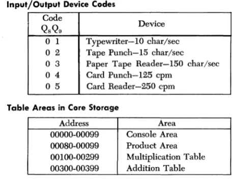
Input/Output Device Codes
Code
Device QSQ9
o
1 Typewriter-1O char/seco
2 Tape Punch-I5 char/seco
3 Paper Tape Reader-I50 char/sec 04 Card Punch-I25 cpm [image:26.271.27.256.27.215.2]o
5 Card Reader-250 cpmTable Areas in Core Storage
Address Area
Typewriter
Typewriter Control Codes
Qn
Control Function1 Space
2 Return Carriage
8 Tabulate
Manual Adjustments to Typewriter
Impression Indicator. The lever under this window can be positioned in settings from 0 to 10 to determine the force with which the type bars strike the paper. The higher the indicator setting, the harder the type bars strike. To test for the correct setting, move the indicator up until the comma and period print distinctly but not heavily. Use a higher setting for multiple copies, but be sure that the multiple copy lever is also correctly set before finally adjusting the impression.
Tab Clear Lever. To clear tab stops, tabulate to the point to be cleared and depress the clear lever. To clear all stops at once, position the carriage at the right margin, hold down the clear lever, and return the carriage to the left margin stop.
Tab Set Lever. To set tabular stops, move the carriage to the desired position and depress the set lever. Set tab st,ops only when the indicator pointer is in line with a white marking on the front paper scale below it.
Carriage Release Lever. Depress the lever on either side to free the carriage and manually move the carriage to the right or left.
Paper Release Lever. To free the paper for positioning or quick removal, move this lever forward.
Line Space Lever. Moved to position 1, 2, or 3, the line space lever provides for single, double, or triple line spacing, respectively.
position for each additional three to five copies. Heavy print at the top of characters shows that the platen is too far back; heavy print at the bottom of characters shows that the platen is too far forward. The shilling mark (/) is a good character to use in checking multiple copy settings.
Left-Hand Margin Set. The left margin stop is set as fol-lows;
1. Return the carriage to the present left margin stop. 2. Depress the margin set key.
3. Manually move the carriage as near as possible to the position desired. The back space key and space bar are convenient to use to obtain the exact position desired, with the margin set key depressed. 4. Release the margin set key.
Right-Hand Margin Set. The right margin stop is set as follows:
1. Move the carriage to the left until stopped by the right margin stop.
2. Depress the margin set key.
IBM 1621 Paper Tape Reader and
IBM 1624 Tape Punch
Paper Tape Tracks and Codes
~O • • • 0
TRACKS :~8A8CDEFGH1,JICLMNOPQRSTUVWXYZI234567890·1 • • ( ,t= . - b / @
E L _
O_X_-_
:::oI*~~!~~;tmtH~'~Id-~~~
CHECK_ , • • !i
•
•
•
.. .
8_'..
•
FEED_ • • • • • • • • • • • • • • • • • • • • • • • • • • • • • • • • • • • • • ... ! .... ~ ...
4 _ _ ' . . •
,_2 ___ :::
:
~~~~~~~~~~~~~~
Loading the Paper Tape Reader
Paper tape can be handled in three forms; the procedure for loading each one varies slightly.
STRIP FORM
Small strips of tape may be loaded directly onto the read head with the following procedure:
1. Position the reel switch to STRIP.
2. Open the tape guides, form an inverted U (f!) with the leading 12 inches of paper tape, and install the tape around the read head with sufficient tension to keep the runout and tape tension contacts closed. Start on the takeup reel side of the read head. Run a finger up over the tape on top of the read head, smoothing the tape down with a firm, moderate pressure so that the tape tension bar is slightly de-pressed and the right side of the feed pinwheel engages the tape feed holes. Be careful not to tear the feed holes. The tape feed holes must mesh with both sides of the. pinwheel.
3. Close the tape guides.
CENTER ROLL FEED
The center roll feed eliminates the necessity for rewinding paper tape rolls to expose the starting end of the tape on the outside of the tape roll. Tape is supplied from the inside of the center roll feed, to the supply reel, around the read head, and onto the takC'lup reel.
The procedure for loading paper tape from the center roll feed is as follows:
1. Position the reel strip switch to REEL.
3. Open the tape guides and form an inverted U (n) with the center section of the first eight feet of paper tape. Wrap the paper tape around the read head with sufficient tension to keep the runout and tape tension contacts closed. Start on the takeup reel side of the read head. Run a finger up over the tape on top of the read head, smoothing the tape down with a firm, moderate pressure so that the tape tension bar is slightly depressed and the right side of the feed pin-wheel engages the tape feed holes. Be careful not to tear the feed holes. The tape feed holes must mesh with both sides of the pinwheel.
4. Close the tape guides.
5. Thread the leading section of paper tape under the guide roller, between the stationary buffer rollers and buffer arm rollers, and onto the takeup reel. 6. Thread the paper tape from the right side of the read
head, under the guide roller, between the stationary buffer rollers and buffer arm rollers, over the supply reel (the rubber drive hub must be installed), around the tape guide stand, and around the tape reel nylon roll.
7. Lower the idler roller onto the supply reel. 8. Lower the buffer arms gently.
9. Depress the reel power key. The buffer arms should swing down to a neutral position, applying tension to the paper tape.
NOTE: The roll of paper tape must be positioned centrally, or evenly, around the center rollers to prevent excessive vibration during reading.
REEL
A reel of paper tape may be read on the 1621 by remov-ing the rubber drive hub from the supply reel and mount-ing the reel of tape in its place. The tape is threaded from the right-hand side of the reel, directly to the stationary buffer rollers, and to the takeup reel as described under CENTER ROLL FEED.
Loading the Tape Punch
forward to facilitate threading. An unwound section of tape is then threaded as follows:
l. Through first tape guide. 2. Inside second tape guide. 3. In front of tape tension guide. 4. In back of tape lever.
5. Between the punching mechanism and the punch guide block, which can be seen in front of the tape. 6. Between the guides on the tape retainer. With the end of the tape held to the left, the tape retainer is returned to normal position, which causes the pins on the feed roll to pierce through the blank tape. The tape lever simultaneously returns to normal position with the top guide above the tape.
The tape feed key is used to repetitively punch auto-matic feed punches and to provide a leader section of paper tape. The approximately 60" of leader needed for threading paper tape on the 1621 can be obtained from the 1624 in 40 seconds. The leader is threaded into the 1624 takeup reel so that the top edge of the tape is at the outside of the reel.
Correction of Incorrect Tape Punch
If a character with incorrect parity is transmitted from core storage and punched, or a valid character is incorrectly punched, the tape feed does not advance. The computer stops in both the automatic and manual modes, and the automatic and manual lights and punch no feed and write check lights on the 1620 console are turned on. Functions of these lights are described under IBM 1620 CONSOLE.
Pro-gram processing can be resumed with the following pro-cedure:
1. Position the 1624 tape feed switch ON.
a. The feed code (all punches) is punched over the incorrect character.
b. The punch no feed and write check lights are turned off.
c. The machine is returned to manual mode only. 2. Depress the start key on the 1620 console.
a. The original character from storage is again punched. If an incorrect character still persists, the record may be corrected, if desired, before processing continues.
If the 1624 runs out of paper tape, the machine stops in automatic mode and the punch no feed light turns on. The "character correction procedure" outlined is used to restore operation.
When this procedure is used to correct the incorrect punching of a valid character and the character is re-'punched incorrectly, the SIE key (described under STOP/ SIE KEY) can be used as follows to determine the cause of the incorrect punching:
Use the SIE key to execute one instruction at a time. When the write check light is turned on, observe the
MBR display (described under REGISTER DISPLAY INDICA-TORS) to determine if the character is valid. If it is, notify
an IBM Customer Engineer.
A transient condition may cause the write check light (but not the punch no feed light) to come on even though a valid character has been correctly punched. Should this occur, briefly turn on the tape feed switch to turn off the write check light, then depress the console start key and proceed with the program.
The punch registration (proper hole spacing) can be verified by the use of a standard paper tape gage. Off-line punching equipment can be checked in the same manner.
Paper Tape Splicing Procedure
A splice should only be made in non-data portions of paper tape because correct reading cannot be assured at the point of splice. Some methods of splicing chad tape in the data portions are possible, but the reading accuracy is not reliable. The reading mechanism feeds and guides the tape by means of the feed holes; therefore they should not be restricted in any way by splices. Splice specifica-tions are:
1. The total thickness of the tape must not exceed 0.010 inch (nominal paper tape thickness is 0.004 inch). 2. The tape overlap at the splice should be no more
than one tape code long (0.100 inch). 3. The splice must be as strong as the tape. 4. The splice must be no wider than the tape.
5. The splice must be free of staples and gummy sub-stances.
The following procedure may be used to splice two lengths of paper tape together.
1. Punch tape feed code into the two ends of the tape to be spliced together.
3. Holding the ends of the tape with the tape feed holes toward you, overlap the tape end in the left hand over the tape endin the right hand by approximately
lha
inch.4. Glue in this position with holes aligned, using a quick-setting glue such as IlIM tape mucilage, PIN 22lO30.
Operating Switches and Lights
Power Switch. With this switch on, all necessary power for operation of the 1621 is supplied by the 1620.
Reel Strip Switch. In reel mode, tape is fed from the supply reel and to the left, onto the takeup reel. In strip mode, short pieces of tape may be read without reel operation.
Reel Power Key. Operates the supply and takeup reels to position the paper tape for reading and to place the machine in ready status.
Nonprocess Runout Key. Causes paper tape to feed. Ready status is terminated and all data transfer is blocked until all paper tape has passed. Paper tape must be reloaded and the reel power key depressed before the machine can be returned to ready status.
Power On Light. Light on indicates that power is supplied
IBM 1622 Card Read Punch
Operator Keys and Lights
CARD READER
Reader On/Off Switch. Used to supply power to the reader and to turn on the power ready light. The 1620 power on/off switch must be on to make the 1622 reader on/off switch active.
Load Key. Causes data from the first card to be checked, read into buffer storage, and automatically transferred in numerical mode to core storage positions 00000-00079. Upon completion of this data transfer, another card feed cycle occurs which loads buffer storage with data from the second card. The 1620 then simulates release and program start at 00000. The instructions from the first card, now in 00000-00079, can be used to continue loading the program or to begin processing. The 1620 must be reset and in manual mode to make the load key operate correctly.
Start Key. Used ( 1) to run in cards, which are then placed under program control (data from the first card is checked and loaded in input buffer storage); (2) to set up a runout condition, which permits programmed read-ing of the cards remainread-ing in the feed when the hopper has become empty; and (3) to restore ready status after the reader has been stopped by a depressed stop key, an . empty hopper, an error, a misfeed. or a transport jam.
Stop Key. Used to stop the read feed at the end of the card cycle in progress and/or to remove the reader from ready status. Data entered into buffer storage during the read cycle in progress is transferred to core storage. The computer continues processing until the next read card command causes a reader no feed stop.
Reader Ready Light. Turns on to indicate that the first card has been loaded into buffer storage with the start key, without a reader check error. It is turned off by a depressed stop key, a reader check error, a transport jam, a misfeed, or an empty hopper.
Reader Check Light. Turned on by an unequal compari-son between the read and check stations and by in-correct parity detected in buffer storage during card read. When there is an unequal comparison; the reader is stopped, ready status is terminated, and the buffer storage data just read cannot be transferred to core storage on the next read command.
1620 Console Read Check Light. The 1620 read check ( 06) indicator and console read check light are turned on by a 1620 parity error during a buffer-storage to core-storage transfer.
1620 Console Reader No Feed Light. Turns on each time the reader is selected by a read command.. The light remains on if the reader is not in ready status and the read command cannot be executed.
CARD PUNCH
Punch On/Off Switch. Used to supply power to the punch and to turn on the power ready light. The 1620 power on/off switch must be on to make the 1622 punch on/off switch active.
Start Key. Used to feed cards to the punch station initially or after an error and nonprocess ronout, and to re-estab-lish ready status after an empty hopper, a misfeed, a transport jam, or a depressed stop key.
Stop Key. Used to stop the punch feed at the end of the card cycle in progress and/or to remove the punch from ready status.
Check Reset. Used to reset error circuits and turn off the punch check light. A start key or nonprocess runout key depression follows, as described under ERROR RESTART PROCEDURES.
Select N-Stop - Select Stop Switch. Used to control the stopping of the punch when error cards are selected into the punch error select stacker. With the switch set to STOP, the punch feed stops with the error card in the select stacker. '
Nonprocess Runout Key. Following a punch check error, depression of the nonprocess runout key resets the error circuits and causes the punched card that is between the punch station and the punch check station to feed into the stacker. If this card is in error also, it follows the first error card into the select stacker and causes the punch check light to turn on again. The next two ( blank) cards go into the nonselect pocket. These cards should be removed before further processing.
This key is also used to run out and check the last punched card of a job. Cards must be removed from the hopper to make the nonprocess runout key operative.
Punch Ready Light. Indicates that the 1622 has a card in punch position and will respond to a write command from the 1620. The ready light is turned off by a punch check error, an empty hopper, a full chip box, a de-pressed stop key, a transport jam, or a misfeed.
Punch Check Light. Turns on when there is an unequal comparison between the data punched and the data read (one card feed cycle later, at the check station), or when a 1622 parity errors occurs during punching (select stop switch set to STOP). The machine stops,
and ready status is terminated.
Chip Light. Indicates that the chip box should be emptied.
1620 Console Write Check Light. Turned on by a parity error during a core-storage to buffer-storage transfer.
1620 Console Punch No Feed Light. Turns on each time the punch is selected by a write command. The light remains on until the punch unit is ready to execute the command.
READ PUNCH COMMON LIGHTS
Stacker Light. Turns on when a stacker is full. Both feeds are stopped temporarily and removed from ready status; the ready light remains on. Operation is resumed auto-matically after the stacker is emptied.
Transport Light. Turns on when a card jam has occurred in either the read or punch feed or above any stacker. \-\Then this occurs, both feeds are stopped and removed from ready status. Both start keys must be depressed to resume operation after the condition is corrected.
Thermal Light. Turns on if the internal temperature of
the 1622 becomes excessive. After several minutes de-lay, the 1620 console reset key may be depressed to turn off the thermal light. If depression of the reset key turns off the thermal light, the 1620 power switch must be turned off and then on again. Operation may be resumed after the power ready light is turned on.
Error Restart Procedures
READER CHECK ERROR
Cause: Unequal comparison between the read and check
stations, or a buffer storage parity error. The reader stops with the error card (last card) in the select stacker.
Indicators: 1622 reader check light ON.
1622 ready light OFF.
Restart Procedure:
1. Remove cards from the read hopper. 2. Depress the nonprocess runout key.
3. Remove the last three cards from the select stacker. 4. Place these three cards in front of the cards removed from the hopper and replace the deck in the hopper. 5. Depress the start key. The card that caused the error is read into buffer storage again, and if an equal comparison is obtained, the interlocked read instruc-tion is executed and processing continues.
1620 READ CHECK ERROR
Cause: Parity error in the 1620 during data transfer from
1622 buffer storage to 1620 core storage. Reader stops with the "error" card (last card) in the nonselect stacker.
Indicators: 1620 read check light ON.
1622 reader ready light ON. 06 read check indicator ON.
Restart Procedure:
1. Remove cards from the read hopper. 2. Depress the nonprocess runout key.
3. Remove the last card from the nonselect stacker and the last two cards from the select stacker.
5. Insert a branch to the address of the instruction that transfers the error card data from input buffer stor-age to core storstor-age.
6. Depress the start key.
PUNCH CHECK ERROR
Cause: Unequal comparison between the data punched and the data read (one card feed cycle later, at check station), or a 1622 parity error while punching data from buffer storage. If the select stop switch is set to
STOP, the punch stops with the error card in the select stacker.
Indicators: 1622 punch check light ON.
1622 punch ready light OFF.
Restart Procedure: To restart without (1) immediate man-ual correction of the error card or (2) reprocessing of the error card:
1. Depress the check reset key.
2. Depress the start key. Processing continues from the point at which the program stopped.
For manual correction of the error card:
1. Remove the last (error) card from the punch select stacker and correct the error card. Place the corrected card behind those in the punch nonselect stacker. 2. Depress the check reset key.
3. Depress the start key. The interlocked write com-mand for the second card following the error card can now be executed.
For reprocessing of the error card, when one card is
punched out for each card read: 1. Remove cards from both hoppers. 2. Depress both nbnprocess runout keys.
3. Remove the last two cards from the punch error select stacker and the last two (blank) cards from the punch nonselect stacker. Also; remove the last two cards from the read nonselect and the last two cards from the read select stacker.
5. Insert a branch to the address of the instruction that begins the reprocessing of the error card.
6. Depress both start keys.
1620 WRITE CHECK ERROR
Cause: 1620 parity error. The error has not been pundled
into a card.
Indicators: 1620 write check light ON.
07 write check indicator ON.
Restart Procedure: A typeout of the core storage positions
that were transferred indicates whether the data in corc storage is correct. If the data in core storage is incorrcct, reread the card or cards from which this data originated.
Double Punch Detection
IBM 1620 Console
Indicator Displays and Switches
MBR-E (Memory Buffer Register, Even). This light and
indicator are turned on when the digit in the even address portion of the MBR has a parity error. An error stops the machine immediately if the parity check switch is set to STOP.
MBR-O (Memory Buffer Register, Odd). This light and
indicator are turned on when the digit in the odd ad-dress portion of the MBR has a parity error. An error halts the machine immediately if the parity check switch is set to STOP.
MARS (Memory Address Register Storage). This light
turns on when a digit in MARS has a parity error. This is an unconditional machine stop, and is not affected by the position of the parity check switch.
Rd Chk (Read Check). This light and indicator are turned
on when an input character with a parity error is de-tected, prior to conversion of input data to BCD code. An
error halts the machine after the input operation is com-plete, if the
I/O
check switch is set to STOP.Wr Chk (Write Check). This light and indicator are
turned on when an output character with an even num-ber of bits is detected during conversion of output data from BCD to output code. The effect on machine opera-tion as a result of detecopera-tion of this parity error varies, depending on the output device selected, as follows: Typewriter: Error detection halts the 1620 after the output operation is complete, if the I/0 check switch is set to STOP.
Card Punch: The card is not punched; error detec-tion halts the 1620 at the end of an SO-character transfer to output buffer storage, if the I/0 check switch is set to STOP.
Tape Punch: Error detection halts the 1620 as soon as the character is punched and prevents the tape feed from advancing, regardless of the check switch setting.
O'Flow Arith Chk (Arithmetic Check). An overflow that
When the overflow check switch is set to STOP, and the overflow check indicator is turned on, the computer halts at the end of the instruction being executed. If the start key is depressed, the overflow check indicator remains on, and the computer continues to execute in-structions in the automatic mode, until another over-flow occurs.
When the overflow check switch is set to PROGRAM,
and the overflow check indicator is turned on, the ma-chine continues to operate in the automatic mode. The indicator can be interrogated and turned off by the program.
Exponent Check. This light and indicator are turned on
by an exponent overflow or underflow during Automatic Floating Point" operations.
Console Program Switches. There are four modifier
switches in this group. They are labeled PROGRAM SWITCHES on the console and are numbered 1 through 4. A branch occurs when a switch specified by a Branch Indicator (BI-46) instruction is set to ON.
When the switch specified is set to OFF, no branch
occurs from the BI instruction, and the next instruction in sequence is executed.
When a Branch No Indicator (BNI-47) instruction is used to interrogate one of these switches, the branch occurs when the switch is set to OFF.
Register Display Indicators
".temory Buffer Register (MBR). The two stored digits
affected by a core storage address are displayed in the
MER. When the core storage location addressed for dis-play is an even-numbered address, the digit at this location is placed in the MER display in the E (even
line); the 0 (odd) line contains the digit in the next
higher-numbered location. If the core storage location addressed for display is an odd-numbered address, the digit at this location is placed in the MBR display on thc o line; the E line contains the digit in the next
lower-numbered location. When the machine is in alphabetic mode, the complete two-digit representation of an alphameric character may be viewed at one time.
Memory Data Register (MDR). Displays the bit
using the seE key. The digit displayed in the MDR dis-play is duplicated in the MBR-E or MBR-O disdis-play, de-pending on whether the digit read out is located at an even- or an odd-numbered core storage position.
Operation (OP) Register. Displays the bit configuration of
the two digits representing the operation code of the instruction last executed. Flag bits of these two digits are not displayed.
Sense and Branch (S-8). Displays
QH
andQ"
of the Branch Indicator, Branch No Indicator, and Input/Output in-structions from the Sense and Branch Register. Input/ output device codes (digits 01-05) are displayed for Input/Output and Control instructions.Digit Register. Used primarily for diagnostic testing by
IBM Customer Engineers. Displays the digits affecting
MARS during all I cycles. As the multiplication pro-gresses, displays the two product digits "looked up" in the multiply table. The Digit Register stores the partial product during multiplication.
NOTE: On some machines the Sense and Branch Reg-ister and the Digit RegReg-ister are combined into a Digit and Branch Register. The functions of the combined
register are the same as those of the individual registers.
Multiplier. Shows each multiplier digit as it is used
dur-ing a multiply operation.
Memory Address Register (MAR). Displays the bit
con-figuration of the five-digit address in anyone of the eight MARS registers selected by the MAR display selec-tor switch and the display MAR key. There is no Hag bit notation.
Memory Address Register Storage (MARS) Display Selec-tor. The 8-position rotary switch permits selection of
any of the eight MARS registers for display in MAR by de-pressing the display MAR key. The position of the switch can be changed without altering the display. However, the rotary switch should not be turned while the display MAR key is depressed.
Control Gate Indicators
H/P (High/Positive). Shows the condition of the internal
E/Z (Equal/Zero). Shows the condition of the internal equaVzero indicator as a result of the last arithmetic or compare operation.
Bypass. Shows that the MAR address was neither decreased nor increased. Either the increment or decrement light is also on.
Decr (Decrement). Shows that the address routed from MAR to MARS was decreased by 1, unless the bypass light is also on. Both lights on indicate that no decrease occurred.
Incr (Increment). Shows that the address routed frolll MAR to MARS was increased by 1, unless the bypass light is also on. Both lights on indicate that no increase occurred.
Plus 2. Shows that the address routed from MAR to MARS was increased by 2. The increment light must also be on.
Rec Mark (Record Mark). Shows that a record mark was sensed in core storage. The record mark is displayed inMDR.
Branch. Comes on during the I cycle of Branch Indicator and Branch No Indicator instmctions if the branch is to occur during the E cycle.
Recomp (Recomplement). Shows that an add or subtract result will be recomplemented upon completion of til(' computation.
Carry Out. Shows that the result from the add table has a carry (Hag bit) or, that a carry went into a position containing a nine, which causes the carry out light to come on one to three storage cycles later.
Carry In. Turned on by a carry out and shows that a one will be added on the next machine cycle.
IA (Indirect Addressing) Shows that an indirect addressing operation is in progress. It is turned on when a Hag bit is present in the units position of the indirect address.
Field Mk 1 (Field Mark 1). Comes on when the Hag bit in the high-order position of the
Q
field is detected in the MDR.T /C 1 (Tme/Complement 1). Shows that the Q address
data is complemented during arithmetic operations.
Instruction and Execute Cycle Lights
The instruction and execute cycle lights are a visual aid for the console operator in stepping an instruction through I and E cycles with the INSTANT STop/seE key. The I and E lights progress through each cycle with repeated de-pressions of this key.
Input/Output Lights
The input/output lights are used primarily for diagnostic testing by IBM Customer Engineers. The Last Card light has significance for the operator and programmer.
LC (Last Card). This light turns on when data from the
last card has been transferred from 1622 input buffer storage to 1620 core storage, without a parity error.
Control Keys and Signal Lights
Power On/Off Switch - Power On Light. When set to the
ON position, applies electrical power to the computer and turns on the power on light.
Power Ready Light. Comes on when internal machine·
temperature and voltages reach proper·operating values. There is a delay from the time the power on/off switch is positioned ON until operating temperature and volt-ages are ohtained. This delay varies with room tem-perature and the time lapse since power was turned off.
Start Key. Used to start program processing and to put
the computer in automatic mode. It is operative only when the computer is in manual mode.
Automatic and Manual Lights. The manual light ON
The automatic light ON indicates that the computer is in the automatic mode (e.g., while executing a stored program or while entering data into core storage from the typewriter keyboard).
Both the manual and automatic lights are on when an instruction is single-cycled with the seE key.
Reset Key. Used to restore all machine status indicators, machine check indicators, and signal lights to their initial or reset condition. The reset key functions only when the computer is in the manual mode (manual light on). Parity errors can occur if the reset key is used while the computer is in the automatic mode. When the computer is in the automatic mode, the in-stant stop key should be depressed to put the computer in the manual mode and permit use of the reset key.
Insert Key and Insert Light. Depression of the insert key places the 1620 in automatic mode, turns on the insert light, and activates the typewriter keyboard so that direct entry of instructions may be made in numerical mode, starting at 00000 and continuing into higher-numbered storage positions. As many as 100 digits may be keyed in. After the 100th digit is entered, an auto-matic release is initiated and the 1620 returns to manual mode.
When less than 100 characters are entered, entry of the last character should be followed by depression of the console release and start keys, or by depression of the R-S key on the typewriter keyboard. The R-S key combines the release and start functions of the console keys. The R-S symbol is typed as a pennanent record that the R-Skey has been used.
The insert key is operative only when the computer is in the manual mode.
Save Key and Save Light. Turns on the save light and saves the address of the next sequential instruction to be executed. This address is saved in Product Address Register 1 (PR-l). If a multiply operation is perfonned before the saved address is used, the saved address is lost because the contents of PR-l are decremented for each new multiply digit during a multiply operation.
Release Key. Used to terminate any input/output oper-ation, including console keyboard entry of data into core storage. When this key is depressed, manual mode is
initiated, the manual light is turned on, and the insert light is turned off.
The release key is operative only when the computer is in automatic mode and performing an I/O operation.
Stop SIE (Single Instruction Execute) Key. Stops the
com-puter in manual mode at the end of the instruction being cxecuted when the key is depressed.
The STOP/SIE key also serves as a single instruction
c'\ccute key. Successive depressions of the key cause one instruction to be execnted for each depression. The manual light remains on.
Instant Stop/SCE (Single Cycle Execute) Key. Canses the
machine to stop at thc end of the 20-microsecond ma-chine cycle in progress when the key is depressed. Suc-cessive depressions of the key cause single machine cycles. Both the manual and automatic lights remain on.
Check Stop Light. Turned on when the machine stops
because of a parity check. One or more of the parity or I/O check indicators that caused the stop is also on. Thc check stop light is turned off when the check in-dicators are rcset or thc parity or I/O switch is set to
PROGR~M.
Display Mar Key. Operative only when the manual light
is on and the automatic light is off. Depression of the display MAR key causes display of the MARS register to
which thc MARS display selector switch is set.
The rotary switch should not be turned while the display MAR key is depressed.
Reader No Feed Light. Turned on when the computer
attempts a paper tape read or card read operation and the reader is not in the ready status. This not-ready status is often temporary in a card read operation be-cause the buffer is interlocked while the read cycle is in process.
Punch No Feed Light. The punch no feed light is turned
on if one of the following conditions exists:
1. The computer executes a write instruction using the tape punch and there is no paper tape on the feed reel.
4. The card punch is not ready. This not-ready status is often temporary on a card punch operation be-cause the buffer is interlocked while the punch cycle is in process.
Any of these conditions stops the computer in auto-matic mode with both the autoauto-matic and punch no feed lights turned on. When a parity error occurs, the I/O write check light is also turned on. Depression of the. release key disconnects the punch and puts the computer in manual mode. Depression of the reset key, while in manual mode, turns off the punch no feed and I/O write check lights. Manual correction and start procedures can begin after depression of the re-lease and reset keys.
Thermal Light. Turned on if the internal temperatures of the 1620, 1622, or 1623 become too high. Power is turned off, and the power ready light goes off. The thermal light may be turned off by depression of the reset key, after the internal machine temperatures return to normal. The power switch must be turned off and on again before power can be applied to the machine.
Console Operating Procedures
Program Entry from Typewriter
Operation Action Explanation
1. Depress insert key.
2. Type: 36 xxxxx 00100 49 xxxxx (No Q
address)
3. Depress release key.
4. Depress start key.
5. Type program steps and data.
6. Depress release key.
7. Depress start key.
Typewriter is conditioned to enter data into core storage, beginning at location 00000.
Enter instructions to read numerically from typewriter, beginning at the first position of program storage (xxxxx), and branch to first program instruction.
Releases typewriter.
The Read Numerically in-struction, entered in step 2, is executed.
As each character is typed, it is stored at location xxxxx and succeedingly higher core storage positions.
Terminates read instruction.
The next sequential instruc-tion, which is the branch to the first program instruction at xxxxx, is executed.
Program Entry from Paper Tape Reader
Operator Action
1. Depress insert key.
2. Type: 36 xxxxx 00300 49 xxxxx (No Q
address)
3. Depress release key.
Explanation
Typewriter is conditioned to enter (hta into core storage, beginning at location 00000.
Enter instruction to read numerically from paper tape reader, beginning at the first position of program storage ( xxxxx ), and branch to first program instruction.
4. Depress start key. The Read Numerically in-struction, entered in step 2, is executed. The EL character punched in the tape causes a termination of the read in-struction and execution of the next sequential instruc-tion (branch to first program instruction, which was en-tered in step 2).
Program Alteration and Data Entry
Operator Action
1. Depress stop key.
2. Depress save key.
3. Depress insert key.
4. Type: 36 xxxxx 00100 42 (No P or
Q
address)5. Depress release key.
6. Depress start key.
7. Type instructions and data.
8. Depress release key. 9. Depress start key.
Explanation
Halts processing and initiates manual mode.
The address of the next in-struction in sequence is saved in Product Address Register 1 (PR-I).
Typewriter is conditioned to enter data into core storage, beginning at location 00000.
Enter instructions to read numerically from typewriter, beginning at the first position of data entry (xxxxx), and branch to address savcd in PR-I (step 2).
Releases typewriter.
The Read Numerieally in-struction, entered in step 4, is executed.
As eaeh character is typed, it is stored at loeation xxx xx and sueceedingly higher core storage positions.
Terminates read instruction. The next sequential instruc-tion, which is Branch Back
Print Core Storage Data on Typewriter
Operator Action l. Depress insert key.
2. Type one of the fol-lowing:
39 xxxxx 00100
38 xxxxx 00100
35 xxxxx 001 00
3. Depress release key. 4. Depress start key.