2018 International Conference on Modeling, Simulation and Analysis (ICMSA 2018) ISBN: 978-1-60595-544-5
Three-dimensional Cloud Structure Construction with Fractal
Modulation on Actual Measurement
Hong-xia WANG and Xiao-jian XU
*School of Electronics and Information Engineering, Beihang University, Beijing, China
*Corresponding author
Keywords: Cloud, Structure construction, Fractal modulation, Actual measurement.
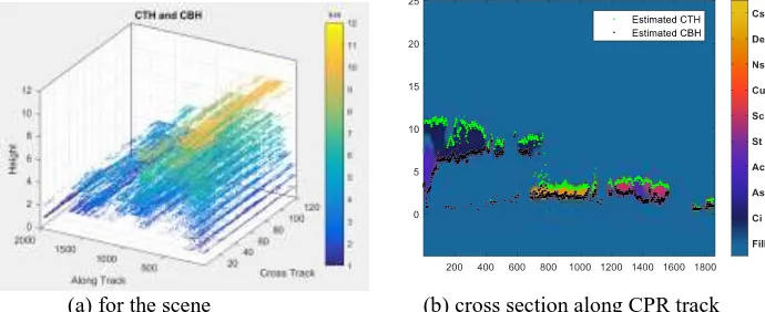
Abstract. A construction method with fractal modulation on actual measurement is proposed to construct three-dimensional cloud structure at specific space-time as well as considering the fractal characteristics. Cloud top height (CTH) and cloud base height (CBH) of recipient pixels are estimated by modulating measurement data with fractal scene of each common type. For recipient pixels without common types, its CBH is resolved by distance-weighted CBH on maximum or few donors whereas its CTH is assigned with the retrieved CTH of the passive sensor. Data from Cloud profile radar (CPR) on CloudSat and Moderate Resolution Imaging Spectroradiometer (MODIS) on Aqua are chosen to validate the proposed strategy. The estimated MODIS CBH and CTH cross section along the corresponding CPR track is presented and compared with that of CPR, resulting in satisfactory coincidence with the boundary of clouds.
Introduction
Cloud top and base heights are important characteristics to describe the impact of clouds on target detection of space-based sensor [1-4]. Cloud top height (CTH) was retrieved from passive radiances, but retrieval of cloud base height (CBH) remains one of the main roadblocks to advancing our understanding of cloud processes due to limited information in passive imagery [1-4]. CBH was estimated by mathematic statistic model or combining cloud classification results with passive surface observed CBH [2]. Dealing with the limitations of passive sensors, a three-dimensional (3D) cloud domain was constructed by the spectral radiance matching (SRM) approach with two-dimensional (2D) cross-sections of cloud properties inferred from profiles of CloudSat and MODIS data [4-6]. Similarly, Miller et al. [7] estimated CBH in MODIS swaths and constructed a 3D tropical storm using cloud-type matching (CTM) method. Li and Sun [8] offered a retrieved data matching algorithm to estimate CBH with cloud top pressures (CTP) and cloud optical thicknesses (COT). CBH across MODIS swaths was also estimated by [9] based on constrained spectral radiance matching (CSRM). However, straight assignments were used in these techniques without considering spatial fractal characteristics of clouds.
In this paper, a construction method is proposed for 3D cloud structure with fractal modulation on actual measurement. The remainder of this article is organized as follows. Section II makes a brief description of data used in the paper. The proposed method to construct 3D cloud structure is given in Section III. Results and analyses are provided in Section IV. Section V summarizes the paper.
Data
30km vertical observation window, resulting in a vertical resolution of 250m [5]. As it moves along the track, CPR detects clouds and achieves detailed vertical structural distribution of various cloud types for any profile.
3D Cloud Structure Construction
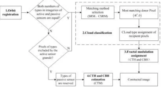
[image:2.595.145.454.204.371.2]Fractal modulation construction method is proposed to construct 3D cloud structure. The method consists of four steps as shown in Figure 1, i.e., orbit registration, cloud classification, fractal modulation assignment and CTH and CBH estimation for reserved types.
Figure 1. Flowchart of 3D cloud structure construction based on fractal modulation.
Orbit Registration
To enable the combination of passive and active sensors, an orbit registration is implemented following the criterion proposed by [10], where (1) is used to seek the most matching MODIS pixel when latitude is not larger than 40º, otherwise (2) is used.
2
2dif Mlat CSlat Mlong CSlong
v v v v v . (1)
2 2
Mlong CSlong Mlat CSlat
err
CSlat CSlong
v v
v v
v
v v
. (2) where vMlat and vMlong are geodetic latitude and longitude of the MODIS pixel in degrees, respectively,
CSlat
v and vCSlong are geodetic latitude and longitude of the CPR pixels in degrees, respectively.
Cloud Classification
m
D is used to denote the distance between the recipient pixel and the track of the active sensor. According to respective dominant positions of SRM [6] and CSRM [9], CSRM [9] is used when
30
m
D km whereas SRM [6] is used when Dm30km. When Dm≤30km
The most matching donor pixel is searched along the track of active sensor by calculating
2
1 2
1
, ,0
, ; ; ,
,
K
k k
k k
r i j r m
F i j m m i m i m
r i j
. (3) where r i jk
, and r mk
,0
denote the radiances of the recipient pixel
i j, and the potential donorThe nearest CPR pixel to the recipient is selected as the best matching donor among first
100f
%pixels in the ascending sequence of F i j m
, ;
. f is a constant and is set to be 0.03. When Dm>30kmCSRM [9] is used when the recipient pixel is away more than 30 km from CPR orbit track. Similarly, among the first
100f
% pixels in ascending sequence forF i j m
, ;
with m1m2200Dm , the nearest donor is selected as the best donor through further constraining by
,
,0
ML ML
F i j F m . (4)
and
ˆ ˆ ˆ
|C i j, C m,0 | C i j, . (5)
where FML denotes multi-layer flag. Cˆ is MODIS-retrieved cloud characteristic parameter such as
CTP and COT. is a ratio factor for tolerating the similarity of a cloud characteristic between recipient and donor. CTP and 0.3 are suggested to use in [9].
Finally, the cloud type of the donor pixel is assigned to the recipient pixel. Only when both numbers of types in the granule imageries of active and passive sensors are not equal, types of passive sensor are reserved for pixels of types excluded by the active sensor granule. The process is repeated until that all recipient pixels have been assigned.
Fractal Modulation Assignment
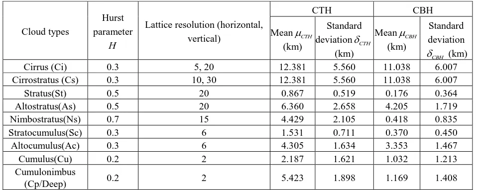
[image:3.595.59.538.517.708.2]Fractal Characteristic Analyses. The fractal image is controlled by two major parameters, i.e., Hurst parameter H and lacunarity r. Fractal dimensionDdepends on Hurst parameterH, D 2 H . Lacunarity r is the ratio controlling resolution, and is reciprocal of lattice resolution shown in Table 1. Hurst parameterHcan be used as the roughness index of fractal curves, the largerH, the smoother curve. Lacunarity r controls the shape of fractal curves. Fractal characteristic parameters and height statistics for few type clouds are shown in Table 1[5]. Cloud height statistics for High in [5] is used to stand for Ci and Cs. Since Cp is a common kind of Deep, their fractal parameters and height statistics are not differentiated.
Table 1. Fractal characteristic parameters and height statistics for few type clouds.
Cloud types
Hurst parameter
H
Lattice resolution (horizontal, vertical)
CTH CBH
MeanCTH (km)
Standard deviationCTH
(km)
MeanCBH (km)
Standard deviation
CBH
(km)
Cirrus (Ci) 0.3 5, 20 12.381 5.560 11.038 6.007
Cirrostratus (Cs) 0.3 10, 30 12.381 5.560 11.038 6.007
Stratus(St) 0.5 20 0.867 0.519 0.176 0.364
Altostratus(As) 0.5 20 6.360 2.658 4.205 1.719
Nimbostratus(Ns) 0.7 15 4.429 2.105 0.418 0.835
Stratocumulus(Sc) 0.3 6 1.531 0.711 0.370 0.450
Altocumulus(Ac) 0.3 6 4.305 1.634 3.353 1.467
Cumulus(Cu) 0.2 2 2.187 1.621 1.032 1.213
Cumulonimbus
(Cp/Deep) 0.2 2 5.423 1.898 1.169 1.408
Fractal Modulation Assignment Process. According to the fractal characteristic of cloud spatial structure, the distribution of CBH and CTH are combined by fractal Brownian surfaces [11].
xd yx, dy
and
x y,
are respectively used to denote positions of recipient and donor. dx and dystand for distances between recipient and donor along and cross track, respectively.
x
2 2
2 2
~ 0, ,along track
~ 0, ,cross track
x
y
H
x x x x x
H
y y y y y
f x d f x N d
f y d f y N d
. (6) thus joint fractal value fxy along two dimensions is calculated by
,
1
xy x y x x y y
f xd yd pf xd p f yd . (7)
where N
is normal distribution function. p is weight factor and is set to be 0.5. x and y arestandard deviation along and cross tracks, respectively. Hx and Hy are Hurst parameters along and
cross tracks, respectively.
The fractal scene is constructed for each type according to the fractal characteristic of cloud spatial structure. Afterward, CBH and CTH of recipient pixel are estimated by modulating those of the optimal donor according to the proportional correlation of recipient and optimal donor pixels in the fractal scene.
CTH and CBH Estimation for Reserved Types
CTH is directly used since it is accurately retrieved by passive space-based sensor. CTM [7] is used to estimate CBH for reserved cloud types. In this paper, the method proposed by [12] is first used to classify clouds in remote sensing images. According to the type of recipient pixel, CBH is calculated by adding that of maximum or few donors with a distance weight. Maximum donors are better for Sc, Cu, Ns and Dc while few donors are better for Ci, As and Ac.
The estimated CBH of recipient pixelHbris given by
1
1 N
bd i
br N
i
i i
H i W d
H
W d
. (8)here Hbd
i is measured CBH of i th recipient pixel. W d
is the distance weight function,
2 1W d d .
d is standard variance of CBH, which depends on cloud type, region and reason. Global
d is used here from Fig 3(a) of [7]. d is the distance between recipient and donor pixels.N is number of donors, Nmaxdonor400, Nfewdonormax
d 1km, 2
, 1km is standard variance of CBHfor pixels within 1km distance.
Results and Analyses
[image:4.595.225.372.588.726.2]Data from CPR on CloudSat and MODIS on Aqua are used to validate the proposed strategy. The MODIS scene from 02:40 to 02:45 at June 1, 2015 is adopted in this work as Figure 2 shown [13].
Figure 2. MODIS RGB (Red, Green and Blue) scene from 02:40 to 02:45 at June 1, 2015 [13].
and MLwater. For each type in this scene, the spatial distribution of fractal relationship is fixed by Brownian movement simulation according to parameters in Table 1. Cirrus is referred to as an illustration. For cirrus, Hurst parameter is 0.3 whereas lattice resolutions are 5 and 20, that is to say, lacunarity parameters are 0.2 and 0.05 in the horizontal and vertical direction, respectively. Consequently, the primary and modulated fractal curves of cirrus in the horizontal and vertical direction are shown in Figure 3. Fractal curves of cirrus plotted in Figure 3(b) are calculated by modulating Figure 3(a) with height statistics.
Horizontal
Vertical
[image:5.595.130.471.178.323.2](a) Primary (b) modulated with height statistics
Figure 3. Primary and modulated fractal curves of cirrus in the horizontal and vertical directions.
After obtaining the spatial distribution of fractal relationship for each type in the scene, cloud structure is constructed by modulation on the CBH and CTH of optimum donors according to the fractal curves for each type.
The estimated CBH and CTH of the scene are presented in Figure 4(a). To verify the effectiveness of the proposed method, their cross sections along CPR track are presented and compared with that of CPR as Figure 4(b). In Figure 4(b), cloud type cross sections from CPR are presented with overlapped estimated CBH and CTH. Green points stand for estimated CTH while black points are for CBH. It can be seen that estimated CBH and CTH coincide well with the boundary of clouds.
(a) for the scene (b) cross section along CPR track
Figure 4. Estimated CBH and CTH.
Summary
[image:5.595.120.465.471.612.2]Acknowledgements
We would like to thank MODIS and Cloudsat science team for providing excellent and accessible data products that made this study possible.
References
[1] Y Noh, J M. Forsythe, S D. Miller, C J. Seaman, Y Li, A K. Heidinger, D T. Lindsey, M A. Rogers and P T Partain, Cloud-Base height estimation from VIIRS. Part II: a statistical algorithm based on A-Train satellite data, Journal of Atmospheric and Oceanic Technology. 34 (2017) 585-598.
[2] J M Forsythe, T H V Haar, D L Reinke, Cloud-base height estimates using a combination of meteorological satellite imagery and surface reports. J. Appl. Meteorol. 39 (2000) 2336–2347.
[3] A Behrangi, S P. F. Casey, B H. Lambrigtsen, Three-dimensional distribution of cloud types over the USA and surrounding areas observed by CloudSat, International Journal of Remote Sensing. 33 (2012) 4856-4870.
[4] S Platnick, M D King, K G Meyer, et al, MODIS cloud optical Properties: User Guide for the Collection 6 Level-2 MOD06/MYD06 Product and Associated Level-3 Datasets. 2015.
[5] Z. Wang, and K. Sassen, Level 2 Cloud Scenario Classification Product Process Description and
Interface Control Document, Available at
http://irina.eas.gatech.Edu/EAS_Fall2008/CloudSat_ATBD_L2_cloud_clas.pdf. 2007.
[6] H. W. Barker, M P. Jerg, T. Wehr, S. Kato, D P. Donovan, R J. Hogan, A 3D Cloud-construction Algorithm for the EarthCARE Satellite Mission, Quart. J. Roy. Meteorol. Soc. 137 (2011) 1042-1058.
[7] S. D. Miller, J M. Forsythe, P T. Partain, J M. Haynes, R L. Bankert, M. Sengupta, C. Mitrescu, J D. Hawkins, T H V Haar, Estimating Three-Dimensional Cloud Structure via Statistically Blended Satellite Observations, J. Appl. Meteorol. Climatol. 53 (2014) 437-455.
[8] H R, Li X J Sun, Retrieving cloud base heights via the combination of CloudSat and MODIS observations. In SPIE Asia Pacific Remote Sensing, SPIE 92591F-92591F-6. Beijing, 2014
[9] X. J. Sun, H R. Li, H W. Barker, R W. Zhang, Y B. Zhou, L. Liu, Satellite-based Estimation of Cloud-base Heights using Constrained Spectral Radiance Matching, Quart. J. Roy. Meteorol. Soc. 142 (2016) 224-232.
[10] H. Wang, X. Xu, Cloud classification in wide-swath passive sensor images aided by narrow-swath active sensor data, submitted to International Journal of Remote Sensing, 2017.
[11] F Yang, Z Zheng, R Xiao, H Shi, Comparison of two fractal interpolation methods, Physica A. 469 (2017) 563-571.
[12] H. Wang, X. Xu, Detection and Classification for Single and Multilayer Cloud Types in Remote Sensing Image. China. Patent. CN201610237086.9. (2016).
![Figure 2. MODIS RGB (Red, Green and Blue) scene from 02:40 to 02:45 at June 1, 2015 [13]](https://thumb-us.123doks.com/thumbv2/123dok_us/275901.1028011/4.595.225.372.588.726/figure-modis-rgb-red-green-blue-scene-june.webp)