2017 2nd International Conference on Artificial Intelligence and Engineering Applications (AIEA 2017)
ISBN: 978-1-60595-485-1
Analysis of Feasibility of Peak Cooling Device Used
with Direct Air Cooling Unit in Power Plant
XING CAO, JINFENG ZHAO, DUANDUAN NIU, YAN JIANG and YINGAI JIN
ABSTRACT
In order to reduce the back pressure of direct air cooling unit and increase power output of steam turbine in summer, the cold end system of a power plant is optimized through adding evaporative condenser as peak cooling device. Through experiments, this article compares the effect on back pressure in the case of inputting the peak cooling device and cutting off peak cooling device with different load and different temperature in summer, also the effect of ash deposition on exhaust pressure is studied. The results show that the unit in different load of 500WM, 400WM, 380WM, 300WM and different temperature of 29℃,33℃,30℃
,27℃ respectively, when putting into the peak cooling device, back pressure reduces 22kPa,13.1kPa,10.8kPa,6.7kPa respectively; when cutting off the peak cooling device, the back pressure increases 27kPa, 14kPa, 11.4kPa and 5.4kPa respectively. The ash deposition can increase the back pressure. The back pressure has been reduced about 9kPa after cleaning ash deposition when cutting off the peak cooling device.
KEYWORDS
Direct air cooling unit, Evaporative condenser, Peak cooling device, Back pressure, Ash deposition
INTRODUCTION
In order to reduce the back pressure of direct air cooling unit and increase power output of steam turbine in summer, most direct air cooling units have been used peak cooling device. Douglas analyzed the back pressure of evaporative condenser system was lower than water cooling system and air cooling system [1]. American Trade winds companies sawmill power generation system and Canada's Trans Alta energy companies combined power generation system use the evaporative condenser, and the application effect is significant [2].
_________________________________________
Xing Cao, Jinfeng Zhao, Jilin Province Electric Power Science Research Co Ltd, Changchun, Jilin, 130021, China
Corresponding author: Duanduan Niu College of Automotive Engineering, Jilin University, Changchun, Jilin, 130022, China; 1941708406@qq.com;
Figure 1. Combined operation diagram of air-cooled condenser and evaporative condenser.
FAN Xiao-chao introduce peak load spray humidification changed in Datang Binchang power generation Co. Ltd, solved the problem of high back pressure and limited load [3]. Professor Zhu Dongsheng's team developed vertical and plate shell evaporative condensers for power plants [4]. This paper analyzes the actual operation of a power plant in Jilin Province, used the evaporative condenser to improve the heat dissipation capability of the exhaust end. The experimental data have a good reference value for the combined operation of direct cooling and peak cooling in domestic power plants.
ARRANGEMENT AND WORKING PRINCIPLE OF PEAK COOLING DEVICE
Arrangement of Peak Cooling Device
The air cooling system is equipped with a peak cooling device which operates in parallel with the direct air cooling system, the unit uses evaporative condenser as peak cooling device, the process is as follows: The exhaust pipe is added from the existing exhaust pipe of turbine into the evaporative condenser, the exhaust pipe is provided with expansion joints and electric butterfly valve. When back pressure is high, open the electric butterfly valve so that part of the steam flow to the serpentine coil of evaporative condenser. Cooling water through the water supply system evenly sprayed on the serpentine coil, utilized the latent heat of cooling water to condense the steam turbine. After cooled, the condensed water is returned to the exhaust device and mixed with the condensed water by direct air condenser, enter the main condenser water system finally. When back pressure is low, close the valve, so that all the exhaust through the direct air cooled unit to condense. Combined operation diagram of air-cooled condenser and evaporative condenser is shown in Fig.1.
The working principle of evaporative condenser
The cold end system of a power plant is optimized and transformed, and added the evaporative condenser of peak cooling device. The exhaust steam of turbine is
Turbine Air-cooled condenser
Evaporative condenser
to realize the circulation of the spray water. The nozzle is equipped with a water collector, to avoid the water droplets are taken away. The evaporative condenser mainly uses the latent heat of water evaporation, the heat exchange mechanism is advanced and efficient, and the effect of heat transfer depends on the local wet bulb temperature. Condensation temperature (back pressure) is low, due to the evaporation of water latent heat, less water can meet the demand of heat exchange, and the device is highly efficient, with less freight and a lower investment.
PERFORMANCE TEST OF PEAK COOLING DEVICE
Under the condition of different load and different temperature, rated fan speed, inputting and cutting off peak cooling device on the unit to test. Basic parameters of power plant unit are shown in table 1:
Unit power and ambient temperature: 500WM-29℃, 400WM-33℃, 380WM-30
℃, 300WM-27℃.The test data is recorded every 30 seconds.
Figure 2 shows change curve of unit back pressure after inputting and cutting the peak cooling device during 300WM 27℃.The test time is 20: 00-21: 00,19: 30-19: 50 of the day. It can be seen from the figure that the back pressure of the unit started to decrease rapidly after operating 5 minutes of peak cooling device, and the back pressure began to stabilize from 30.2 kPa to 13.9 kPa after operating 30 minutes and the back pressure dropped by 6.7 kPa and decreased by 33.2%. After the peak cooling device was removed, the unit back pressure started to rise sharply and stabilized eventually, rose from 15.3KPa to 20.7kPa, and the back pressure increased by 5.4kPa and increased by 26.1% in 20min.
Figure 3 shows change curve of unit back pressure after inputting and cutting the peak cooling device during 380WM 30℃. The test time is 12:25-13:30, 11:30-11:50 of the day. It can be seen from the figure that the back pressure started to decrease rapidly after operating peak cooling device, and the back pressure began to stabilize from 27.3 kPa to 16.5 kPa and the back pressure dropped by10.8kPa and decreased by 39.6% . After the peak cooling device was removed, the unit back pressure started to rise from 17.1kPa to28.5kPa, and the back pressure increased by 11.4kPa and increased by 66.7%.
TABLE 1. BASIC PARAMETERS.
Main Parameters Unit of Parameter Data
Power output of unit MW 660
Main steam pressure MPa 24.2
Reheat steam pressure MPa 3.65
High pressure cylinder exhaust pressure MPa 4.05
Back pressure kPa 10
Figure 2. Change curve of unit back pressure after inputting and cutting the spike cooling device during 300WM 27℃.
[image:4.612.196.400.410.690.2]
Figure 4. Change curve of unit back pressure after inputting and cutting the peak cooling device during 400WM 33℃.
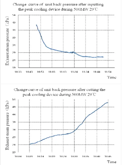
Figure 5. Change curve of unit back pressure after inputting and cutting the peak cooling device during 500WM 29℃.
Figure 5 shows Change curve of unit back pressure after inputting and cutting the peak cooling device during 500WM 29℃. The test time is 10:50-11:50, 10:00-11:40 of the day. It can be seen from the figure that the back pressure starts to decrease rapidly after operating peak cooling device, and the back pressure begins to stabilize from 47.8kPa to 26.2 kPa and the back pressure drops by21.6kPa and decreased by 45.2%. After the peak cooling device was removed, the unit back pressure started to rise from 24.5kPa to52.6kPa, and the back pressure increased by 26.1kPa and increased by 49.62%.
In the case of little change of ambient temperature, in the high-load operation, the back pressure can be reduced by about 10kPa, the effect of operating peak cooling device is good. However, in the low-load operation, the effect is poor relatively.
EFFECT OF ASH DEPOSITION ON EXHAUST PRESSURE
Figure 6. Change curve of unit back pressure after inputting and cutting the peak cooling device during 380WM 30℃ (Air cooling island after cleaning ash).
Figure 6 shows the experimental study of air cooling island after cleaning ash during 500WM 29℃. The test
Time is 10: 50-11: 50, 10: 00-10: 40 of the day. It can be seen from the figure that the back pressure started to decrease rapidly after operating peak cooling device, and the back pressure began to stabilize from 19.3kPa to 14.8 kPa and the back pressure dropped by 4.5 kPa and decreased by 23.32%. After the peak cooling device was removed, the unit back pressure started to rise from 16.7 kPa to 19.3kPa, and the back pressure increased by 2.6kPa and increased by 15.57%.
It can be seen from Figure 6, after the air-cooled island cleaning, putting the peak device, the exhaust pressure reduced to 15 kPa, the exhaust pressure before cleaning ash reduced to 16 kPa; After the peak cooling device was removed , the exhaust pressure rose sharply, and finally stabilized at about 19.3 kPa. The exhaust pressure before cleaning ash reduced to 28.5 kPa, difference between two about 9kPa. It can be seen that existence of ash will increase the back pressure.
CONCLUSION
This paper states on the feasibility of peak cooling device which is used in a direct air cooling unit. We are contrast and analysis the changes of back pressure after inputting and cutting off peak cooling device in summer .The conclusions as follows:
2. The efficiency of the peak cooling device is affected by ambient temperature and load. When the load is more than 380MW, and the exhaust pressure can be reduced by an average of 10 kPa when peak cooling device is in use. The more the load increases, the more exhaust pressure decreases.
3. For power plants which have been put into direct air cooling unit, in order to reduce the back pressure of direct air cooling unit and increase power output of steam turbine in summer, it is necessary to use the peak cooling device to increase the heat dissipation capability of the exhaust end.
4. The existence of ash on the tube bundle of the air-cooled unit will decrease the heat transfer performance of the condenser and cause back pressure to rise. Heat transfer performance is improved and the back pressure is reduced after cleaning up the ash.
ACKNOWLEDGEMENTS
The programmer [Improving the Combustion Mode and Security Running Control Strategy to Decrease the Pollution in Northeast of China (UK-CIAPP\201)] was supported by the Royal Academy of Engineering under the UK-China Industry Academia Partnership Programmed scheme. The authors are grateful for the support of the Royal Academy of Engineering and the UK government's Newton Fund. This work was also supported by project “Study on cold junction optimization of the parallel operation system of air cooled condenser and peak heat exchanger and the heat transfer characteristics of the system, No.: KY-GS-17-01-06”.
Corresponding author: Duanduan Niu, College of Automotive Engineering, Jilin University, Changchun, Jilin, 130022, China; 1941708406@qq.com.
REFERENCES
1. Hutton, David. Improved Power Plant Performance with Evaporative Steam Condensing [J]. CTI Journal, 1999, 20(1): 34~58.
2. Douglas Smith. Power Plant Cooling Systems: The Unsung Heroes [J]. Power Engineering, 2001, 105(5): 55~62.
3. Xiaochao Fan, Yue Dang, Jinglin Shi, et lathe Change and Performance Analysis of Peak Load Cooling System Used in 600MW Direct Air Cooling Unit [J]. Turbine Technology, 2013, .55(4):300-302.
4. Changqing Guo, Dongsheng Zhu, Changfeng Yan. Research Progress and Application of Evaporative Condenser in Power Generation System [J]. Power System Engineering, 2010, 06: 27-30.
5. Chunyan Wang, Weikang Zhang, Ming Sun, et al. Optimization of cold end system on 660MW supercritical direct air cooling unit [J]. Jilin Electric Power, 2016, 44(2): 49-51.